Burkert 8619 multiCELL WM AC Operating Instructions Manual
8619 series modular transmitter / controller
Hide thumbs
Also See for 8619 multiCELL WM AC:
- Operating instructions manual (194 pages) ,
- Quick start manual (51 pages) ,
- Quick start manual (40 pages)

Related Manuals for Burkert 8619 multiCELL WM AC


Summary of Contents for Burkert 8619 multiCELL WM AC
- Page 1 Type 8619 8619 multiCELL WM AC 8619 multiCELL WM DC 8619 multiCELL Modular transmitter/controller Operating Instructions...
- Page 2 We reserve the right to make technical changes without notice. Technische Änderungen vorbehalten. Sous réserve de modifications techniques. © Bürkert SAS, 2010-2014 Operating Instructions 1412/6_EU-ML 00561096 Original_FR...
-
Page 3: Table Of Contents
Type 8619 General information ................................3 1.1 about this operating instructions ..........................4 1.2 intended use .....................................5 1.3 Basic safety information ..............................6 1.4 General information ................................7 Product descriPtion ................................9 area of application ................................10 2.1 construction of a 8619 multicell ..........................10 2.2 construction of a 8619 multicell Wm dc ......................11 2.3 construction of a 8619 multicell Wm ac ......................12 2.4 functional diagram ................................13 2.5 functional description ..............................13 2.6 2.7 description of the name plate .............................15 technical data . - Page 4 Type 8619 installation procedure ..............................31 4.2 electrical wiring ..................................34 4.3 adjustment and commissioninG ..........................53 5.1 safety instructions ................................56 5.2 switching on the device for the first time ......................56 5.3 using the navigation button and the dynamic keys ..................57 5.4 entering text ..................................59 5.5 entering a numerical value ............................60 5.6 description of the icons ..............................61 5.7 operating levels ...................................62 Process level ..................................63 5.8 configuration level access ............................64 5.9 5.10 "Parameters" menu ................................65 5.11 calibration menu ................................108 5.12 "diagnostics" menu .
-
Page 5: General Information
Type 8619 Type 8619 Generalinformation General informaTion about the operating instructions ..........................4 1.1 1.1.1 Symbols used ............................4 1.1.2 Definition of the word "device" ......................4 intended use .....................................5 1.2 Basic safety information ..............................6 1.3 General information ................................7 1.4 1.4.1 Manufacturer's address and international contacts ..............7 1.4.2 Warranty conditions .......................... -
Page 6: About This Operating Instructions
Refers to information contained in the Operating Instructions or in other documents. → Indicates a procedure to be carried out. 1.1.2 Definition of the word "device" The word "device" used in the Operating Instructions refers to the controller/transmitter type 8619 multiCELL, 8619 multiCELL WM AC or 8619 multiCELL WM DC. English... -
Page 7: Intended Use
Type 8619 Generalinformation 1.2 intended use use of this device that does not comply with the instructions could present risks to people, nearby installations and the environment. ▶ The device is intended, depending on the modules fitted and the measurement sensors connected, for the acquisition, processing, transmission and regulation of physical parameters such as pH, conductivity, tem- perature or flow rate..▶... -
Page 8: Basic Safety Information
Type 8619 Generalinformation 1.3 Basic safety information This safety information does not take into account: • any contingencies or occurrences that may arise during assembly, use and maintenance of the device. • the local safety regulations that the operator must ensure the staff in charge of installation and maintenance observe. -
Page 9: General Information
To contact the manufacturer of the device, use following address: Burkert SAS Rue du Giessen BP 21 F-67220 TRIEMBACH-AU-VAL You may also contact your local Burkert sales office. The addresses of our international sales offices are available on the internet at: www.burkert.com 1.4.2 Warranty conditions The condition governing the legal warranty is the conforming use of the device in observance of the operating condi- tions specified in this operating instructions. - Page 10 Type 8619 Generalinformation English...
-
Page 11: Product Description
Type 8619 Productdescription ProDucT DeScriPTion area of application ................................10 2.1 construction of a 8619 multicell ..........................10 2.2 construction of a 8619 multicell Wm dc ......................11 2.3 construction of a 8619 multicell Wm ac ......................12 2.4 functional diagram ................................13 2.5 2.6 functional description ..............................13 2.7 description of the name plate .............................15 English... -
Page 12: Area Of Application
Type 8619 Productdescription 2.1 area of application The 8619 multiCELL is a multifunction device intended to display, transmit and regulate various physical param- eters. It can be used, for example, to manage a water treatment system (a boiler, a cooling tower or a reverse osmosis system). -
Page 13: Construction Of A 8619 Multicell Wm Dc
Type 8619 Productdescription 2.3 construction of a 8619 multicell Wm Dc A: Wall-mounting housing; Cover with seal, closed by 4 screws; Display with navigation components and LEDs. B: main board (identified by "M0" on the plate) with two digital inputs (identified by "DI", digital input), two 4-20 mA current outputs (identified by "AO", analogue output) and two digital outputs (identified by "DO", digital output). -
Page 14: Construction Of A 8619 Multicell Wm Ac
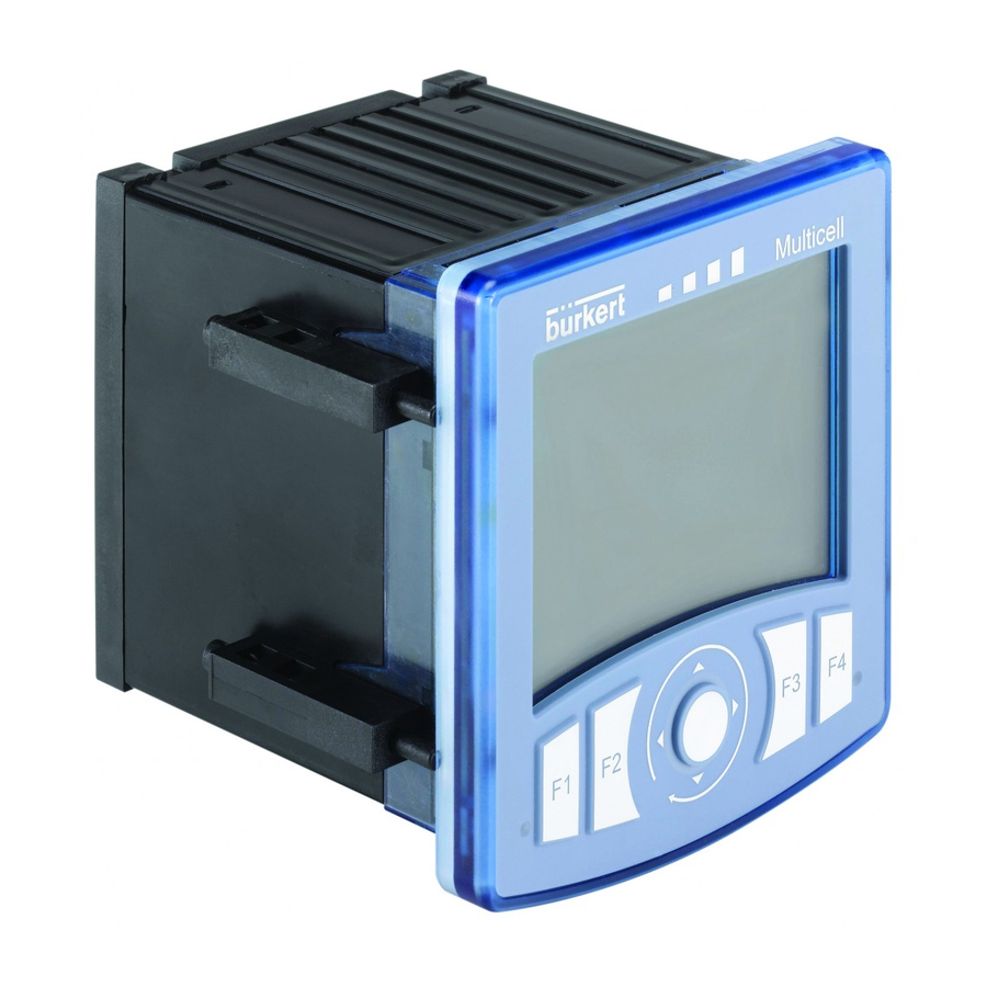
G: Protective cap for the 110-240 V AC power supply terminal board H: 5 M20 x 1.5 cable glands J: supply and distribution board K: display with backlight. L: navigation button (4 directions). M: 4 dynamic keys N: 2 LEDs Fig. 3 : Construction of a 8619 multiCELL WM AC English... -
Page 15: Functional Diagram
Type 8619 Productdescription 2.5 functional diagram INPUTS FUNCTIONS OUTPUTS Digital inputs or frequency Function 1 OUTPUT SIGNAL inputs Analogue inputs, current or voltage PWM or on/ Transistor, off or PFM or 1 and 2 pulse Conductivity sensor (2 or 4 Function 6 electrodes) 4-20 mA, 4-20 mA... - Page 16 Type 8619 Productdescription function availability formula Flow rate • Standard Each digital input can be used to measure the measurement on models flow rate. 560205, 560213, 565984 à 565987 • Optional (see section 5.10.4) on all other models Optional (see Continuous regulation For all input types;...
-
Page 17: Description Of The Name Plate
Type 8619 Productdescription 2.7 Description of the name plate 2xDI - 2xAO - 2xDO - SD CARD 8619 multiCELL pH/ORP - PT100/1000 Supply: 12-36V DC, 1.8 A RES COND 2/4 POLES PT100/1000 Temp: -10...+60 °C 2xAO - 2xDO IP65 PANEL (FRONT) IP20 (REAR) S-N:1110 00560204 Softw.: W44ML 00560204... - Page 18 Type 8619 Productdescription English...
-
Page 19: Technical Data
Type 8619 Technicaldata Technical DaTa conditions of use of the 8619 multicell ......................18 3.1 conditions of use of the 8619 multicell Wm dc ....................18 3.2 conditions of use of the 8619 multicell Wm ac .....................19 3.3 compliance to standards and directives .......................19 3.4 mechanical data ...................................20 3.5 3.6 specifications of the "m0" main board of the 8619 multicell ..............21 3.7 specifications of the "m0" main board of the 8619 multicell Wm ............22 3.8 specifications of the power supply board of the 8619 multicell Wm ..........23 3.9 specifications of the "PoWer out" power distribution board for the 8619 multicell Wm ..24 3.10 specifications of the "input" board ...........................24 3.11 specifications of the memory card reader/recorder ..................25 3.12 specifications of the outputs board "out" ......................25 3.13 specifications of the "ph/redox" module . -
Page 20: Conditions Of Use Of The 8619 Multicell
Type 8619 Technicaldata 3.1 conditions of use of the 8619 multicell Ambient temperature • without connection module • -10 to +70 °C • with connection module • -10 to +60 °C Air humidity < 85 %, not condensing Height above sea level max. 2000 m Protection rating •... -
Page 21: Conditions Of Use Of The 8619 Multicell Wm Ac
• Resistance to vibrations EN 60068-2-6 • Resistance to shocks: EN 60068-2-27 • For the 8619 multiCELL WM AC: Low voltage directive The UL devices with command key PE72 (identified by the logo ) and the UL devices with command... -
Page 22: Mechanical Data
Type 8619 Technicaldata 3.5 mechanical data Tab. 1 : Materials in contact with the ambient air material component 8619 multicell Wm ac or 8619 multicell 8619 multicell Wm dc Panel-mounting housing and fastener Wall-mounting housing, wall-mounting fastening plate, cable glands, protective cap PA66 (for LCD display), protective blank (for a slot without connection terminal), hinge stiffener. -
Page 23: Specifications Of The "M0" Main Board Of The 8619 Multicell
Type 8619 Technicaldata PA66 PA66 Stainless steel 316 (A4) 1 2 3 4 5 6 7 8 9 1 2 3 4 5 6 7 8 9 Stainless steel 304 PBT, contacts in gold-plated PA66 Silicone copper alloy Fig. 6 : Component materials of the 8619 multiCELL WM 3.6 Specifications of the "m0" main board of the... -
Page 24: Specifications Of The "M0" Main Board Of The 8619 Multicell Wm
Type 8619 Technicaldata All analogue outputs ("AO") • 4-20 mA current • Any connection mode, in sink or source mode • Galvanically isolated • Protected against polarity reversal • Max. loop impedance 1100 W to 36 V DC, 610 W to 24 V DC, 100 W to 12 V DC All digital outputs ("DO") •... -
Page 25: Specifications Of The Power Supply Board Of The 8619 Multicell Wm
Type 8619 Technicaldata All digital outputs ("DO") • Transistor • Any connection mode, in NPN or PNP mode • Galvanically isolated • Protected against short circuits • Max. voltage: 36 V DC • Max. 700 mA per transistor; total of max. 1A if both transistors are connected •... -
Page 26: Specifications Of The "Power Out" Power Distribution Board For The 8619 Multicell Wm
Observe the maximum permissible load as a function of the ambient temperature. See the derating curves Fig. 7. Maximum current of the load 8619 multiCELL WM AC, without connection module 8619 multiCELL WM AC, with connection module +20 +30 +40 +50 +60 +70 +80 [°C]... -
Page 27: Specifications Of The Memory Card Reader/Recorder
Type 8619 Technicaldata Analogue inputs ("AI") • Any connection mode, in sink or source mode • Galvanically isolated • Precision ±0.25 % • Current: 0 - 22 mA or 3.5 - 22 mA. Max. voltage: 36 V DC. Impedance: 50 W. Resolution: 1.5 µA •... -
Page 28: Specifications Of The "Ph/Redox" Module
Type 8619 Technicaldata 3.13 Specifications of the "ph/redox" module ph measurement • pH measurement range • -2.00...+16.00 pH • Resolution of pH measurement • 0.01pH • ±0.02 pH + pH probe error • Systematic variation in the pH measurement • -600...+600 mV • Potential difference measurement range •... - Page 29 Type 8619 Technicaldata conductivity measurement (with connected conductivity sensor) • Measurement range • 0.000 µS/cm ... 2 S/cm (depends on the conductivity sensor) • 10 S/cm • Measurement resolution • Systematic variation in the measurement • ±0.5% of the measured value + conductivity sensor error resistivity measurement (with connected conductivity sensor) •...
- Page 30 Type 8619 Technicaldata English...
-
Page 31: Installation And Wiring
4.3.4 Wiring the 12-36 V DC electrical supply for a 8619 multiCELL WM DC ......36 4.3.5 Wiring the 110-240 V AC electrical supply for a 8619 multiCELL WM AC ......36 4.3.6 Supplying an external instrument via a 8619 multiCELL ............37 4.3.7... -
Page 32: Safety Instructions
Type 8619 Installationandwiring 4.1 Safety instructions DANGER risk of injury due to electrical voltage. ▶ If a 12-36 V DC version is installed either in a wet environment or outdoors, all the electrical voltages must be of max. 35 V DC. ▶ Disconnect the electrical power for all the conductors and isolate it before carrying out work on the system. ▶... -
Page 33: Installation Procedure
Type 8619 Installationandwiring 4.2 installation procedure 1. To carry out mechanical installation: Depending on the version, follow the instructions in section 4.2.1 or 4.2.2. 2. To wire the device: Depending on the version, follow the instructions in section 4.3. 4.2.1 installing a 8619 multicell on an enclosure or electrical cabinet →... -
Page 34: Installing A 8619 Multicell Wm On A Support
Type 8619 Installationandwiring Step 5: → Place the fastener flush against the 8619 by hand, so that the hooks remain in place. Step 6: → Fully tighten the screws using an appropriate screwdriver. → Repeat steps 4 to 6 to fit the remaining 3 fasteners. Fig. - Page 35 Type 8619 Installationandwiring Step 1: Removing the wall-mounting fastening plate from the device. 1. Press the tab to unlock the device. 2. Lift the device. 3. Separate the device from the wall-mounting fas- tening plate. Step 2: Installing the wall-mounting fastening plate on the support.
-
Page 36: Electrical Wiring
Type 8619 Installationandwiring 4.3 electrical wiring DANGER risk of injury due to electrical voltage. ▶ If a 12-36 V DC version is installed either in a wet environment or outdoors, all the electrical voltages must be of max. 35 V DC. ▶ Disconnect the electrical power for all the conductors and isolate it before carrying out work on the system. ▶... -
Page 37: Wiring The 12-36 V Dc Electrical Supply For A 8619 Multicell
Type 8619 Installationandwiring Tab. 2 : Specifications of the cables and conductors External diameter of the cable (8619 multiCELL WM) 6 to 12 mm (4 mm if using multiply drilled seals) Cross-section of the local earth connection conductor 0.75 ... 1.5 mm (12-36 V DC versions) Rigid conductor cross-section H05(07) V-U 0.2 ... -
Page 38: Wiring The 12-36 V Dc Electrical Supply For A 8619 Multicell Wm Dc
Type 8619 Installationandwiring 4.3.4 Wiring the 12-36 V Dc electrical supply for a 8619 multicell Wm Dc → Use a filtered and regulated 12-36 V DC electrical power supply. → Use the rightmost cable gland for the electrical power supply cable. → Wire the 12-36 V DC power supply for a 8619 multiCELL WM on a terminal block marked 12-36 V DC. →... -
Page 39: Supplying An External Instrument Via A 8619 Multicell
Put in place and screw on the protective cover. Fig. 12 : Wiring the 110-240 V AC electrical supply for a 8619 multiCELL WM AC 4.3.6 Supplying an external instrument via a 8619 multicell The device can be used to supply an external instrument, for example a flow sensor, with a voltage identical to the supply voltage of the 8619 The power supply is available on the "M0"... -
Page 40: Supplying An External Instrument Via A 8619 Multicell Wm
• is equal to the supply voltage of the 8619 multiCELL WM DC which is supplied with a voltage of 12-36 V DC. • is equal to a voltage of 24 V DC on a 8619 multiCELL WM AC which is supplied with a voltage of 110-240 V AC. - Page 41 Type 8619 Installationandwiring 1st 4-20 mA input (at external instrument) 0 VDC 2nd digital output (at 2nd 4-20 mA input (at external instrument) external instrument) 12-36 VDC Load 1 0 VDC 1st digital output (at exter- nal instrument) 0 VDC 5-36 VDC 12-36 VDC 0 VDC Load 2...
-
Page 42: Examples Of The Connection Of Flowmeters To A 8619 Multicell
Type 8619 Installationandwiring 4.3.9 examples of the connection of flowmeters to a 8619 multicell 12-36 VDC Electrical power supply Removable screw FE = functional earth terminals, 21-posi- tions, orange SUPPLY PWR OUT DI1 AO2 FE Fig. 16 : Wiring the 2 type 8030 flow sensors 8041 8071 Pls- Pls+ 4...20 12-36 VDC Electrical power... -
Page 43: Examples Of The Connection Of A Solenoid Valve To A 8619 Multicell Wm
Type 8619 Installationandwiring 4.3.10 examples of the connection of a solenoid valve to a 8619 multicell Wm The solenoid valve can be connected to the device via board "M0" or via the outputs module, "OUT". → If a solenoid valve is connected to the device, connect a flyback diode in parallel to the solenoid valve. If the solenoid valve is connected via a type 2508 connector, this connector is available with an integrated flyback diode. -
Page 44: Wiring The Input Module "Input
Type 8619 Installationandwiring 4.3.12 Wiring the input module "inPuT" The "INPUT" inputs module has: • Two analogue inputs; • Two digital inputs. The inputs are galvanically insulated, and therefore floating. 1st 0/4-20 mA output (at external instrument) 0 VDC 2nd 0/4-20 mA output (at external instrument) 5-36 VDC 12-36 VDC 1st digital output (at... - Page 45 Type 8619 Installationandwiring 1st 0/4-20 mA output 2nd 0/4-20 mA output (at external instrument) (at external instrument) + - I 12-36 VDC 12-36 VDC 0 VDC 0 VDC 1st digital output (at external instrument) 0 VDC 12-36 VDC 2nd digital output (at external instrument) 0 VDC Removable screw termi-...
-
Page 46: An Example Of The Connection Of A Type 8232 Chlorine Sensor (Order Code 566051 Or 566052) To The Input Module "Input
Type 8619 Installationandwiring 4.3.13 an example of the connection of a type 8232 chlorine sensor (order code 566051 or 566052) to the input module "inPuT". Electrical supply to the Electrical supply to the chlorine sensor chlorine sensor 12-36 VDC 12-36 VDC Removable screw Removable screw terminals, 9-positions, terminals, 9-positions, orange orange 6 7 8 6 7 8 (AI1) (AI2) (DI1) (DI2) (AI1) (AI2) (DI1) (DI2) - Page 47 Type 8619 Installationandwiring 22.5-26 VDC M0: Removable screw terminal, 21-positions, orange Electrical power supply of the 8619 SUPPLY PWR OUT DI1 AO2 FE Brown White Green Yellow Removable screw terminals, 9-positions, orange 6 7 8 (AI1) (AI2) (DI1) (DI2) "INPUT" module of the 8619 FE = functional earth Fig.
-
Page 48: Wiring The Output Module "Out
Type 8619 Installationandwiring 4.3.15 Wiring the output module "ouT" The "OUT" outputs module has: • Two 4-20 mA analogue outputs; • Two digital outputs. The outputs are galvanically insulated, and therefore floating. 1st 4-20 mA 2nd 4-20 mA input (at input (at external external instrument) instrument) 0 VDC 12-36 VDC... -
Page 49: Wiring The "Ph/Orp" Module
Type 8619 Installationandwiring 4.3.16 Wiring the "ph/orP" module • To avoid the influence of disturbances, wire the pH/redox sensor in symmetric mode. In this case, it is compulsory to wire the equipotential electrode. • When the pH/redox sensor is wired in asymmetrical mode, measurement of the pH or the oxidation reduction potential may drift over time when the equipotential electrode is not wired. -
Page 50: Examples Of Connection To Be "Ph/Orp" Module
Type 8619 Installationandwiring Black Temperature sensor Reference electrode pH measurement electrode Strap (not delivered) 6 7 8 Removable screw terminals, 9-positions, grey FE = functional earth Colour of the wires in Bürkert connection cables with order codes 561904, 561905 or 561906. Fig. -
Page 51: Wiring The "Cond" Conductivity Module
Type 8619 Installationandwiring wire colour signal translucent pH sensor red (coax cable reference electrode strap (not shielding) translucent delivered) blue rhodium electrode green/yellow cable shielding grey sensor body 6 7 8 Green Pt1000 Removable screw terminals, 9-positions, grey White Pt1000 FE = functional earth Fig. -
Page 52: Examples Of Connection To The "Cond" Conductivity Module
Type 8619 Installationandwiring Temperature sensor 6 7 8 Removable screw terminals, 9-positions, green FE = functional earth Fig. 32 : Wiring a resistive conductivity cell with 4 electrodes and a Pt100 or Pt1000 temperature sensor in a conductivity module 4.3.19 examples of connection to the "conD" conductivity module FE = functional earth 6 7 8... - Page 53 Type 8619 Installationandwiring wire colour signal Temperature sensor Pink current injection + Green conductivity measurement + Brown conductivity measurement - Yellow current injection - Grey Pt1000 White Pt1000 6 7 8 Blue Pt1000 Removable screw terminals, 9-positions, green FE = functional earth Fig.
- Page 54 Type 8619 Installationandwiring English...
- Page 55 Type 8619 aDjuSTmenT anD commiSSioninG safety instructions ................................56 5.1 switching on the device for the first time ......................56 5.2 using the navigation button and the dynamic keys ..................57 5.3 entering text ..................................59 5.4 entering a numerical value ............................60 5.5 description of the icons ..............................61 5.6 operating levels ...................................62 5.7 Process level ..................................63 5.8 configuration level access ............................64 5.9 5.10 "Parameters" menu ................................65 5.10.1 Setting the 8619 date and time ......................65 5.10.2 Selecting the display language .......................65 5.10.3 Modifying the PARAMETERS menu access code ..............65 5.10.4...
- Page 56 Type 8619 Adjustmentandcommissioning 5.11 calibration menu ................................108 5.11.1 Enabling/disabling the Hold function ..................108 5.11.2 Modifying the Calibration menu access code ................109 5.11.3 Adjusting the current outputs ....................... 109 5.11.4 Calibrating an analogue input AI1 or AI2 connected to a sensor other than a chlorine sensor ..........................
- Page 57 Type 8619 Adjustmentandcommissioning 5.16.1 On the M0:MAIN board ......................... 150 5.16.2 On the input module ........................151 5.16.3 On the pH/redox module ....................... 151 5.16.4 On the conductivity module ......................152 5.16.5 On the additional outputs module ....................152 English...
-
Page 58: Adjustment And Commissioning
Type 8619 Adjustmentandcommissioning 5.1 Safety instructions WARNiNG risk of injury due to non-conforming adjustment. Non conforming adjustment could lead to injuries and damage the device and its environment. ▶ The operators in charge of adjustment must have read and understood the contents of this operating instructions. ▶ In particular, observe the safety recommendations and intended use. ▶... -
Page 59: Using The Navigation Button And The Dynamic Keys
Type 8619 Adjustmentandcommissioning 5.3 using the navigation button and the dynamic keys The arrows displayed show the directions in which you can browse in this view. To activate the dynamic MENU ABORT SAVE OK To activate the dynamic function to the far left, press function to the far right, press LED A: shows the system LED B: shows the sensor status. - Page 60 Type 8619 Adjustmentandcommissioning You want to... Press..select the highlighted character or mode Dynamic function "SEL" ...browse in Process level next view previous niveau niveau view suivant précédent ...browse in the Configuration level menus display the next display the pre- menu vious menu ...browse in the menu functions highlight the next highlight the pre-...
-
Page 61: Entering Text
Type 8619 Adjustmentandcommissioning 5.4 entering text This section describes how to use the keyboard displayed to modify the name of a process variable (13 char- acters max.), a function (12 characters max.) or the title of a view (12 characters max.). Cursor of the data entering area selector Edit name a b c d e... -
Page 62: Entering A Numerical Value
Type 8619 Adjustmentandcommissioning 5.5 entering a numerical value → Accessing, for example, the manual calibration function for a conductivity sensor. Refer to section 5.9 to access the "Calibration" menu. Calibration Mx:Conductivity Manual calibration Cond manual calib After confirming the entered 4.294 S/cm numerical value by pressing "OK", modify the unit selected by 25.01 °C Move the decimal point by... -
Page 63: Description Of The Icons
Type 8619 Adjustmentandcommissioning 5.6 Description of the icons M0:MAIN 29/06/2010 13:40 6.000 20.00 MENU Fig. 40 : Position of the icons icon meaning and alternatives Default icon when process monitoring is not activated via the "Diagnostics" menu; if monitoring is activated, this icon indicates that the parameters monitored are not out of range. If at least one monitoring is activated, the alternative icons in this position are: •... -
Page 64: Operating Levels
Type 8619 Adjustmentandcommissioning 5.7 operating levels The device has 2 operating levels: Process level See section 5.8 for the description of the Process level. configuration level This level comprises 5 menus: Menu title Relevant icon This is when the "Parameters": see section 5.10 device is be- ing parame- tered.... -
Page 65: Process Level
Type 8619 Adjustmentandcommissioning 5.8 Process level M6:Outputs 29/06/2010 13:40 M2:Conductivity 29/06/2010 13:40 mS/cm 29/06/2010 M1:pH 13:40 29/06/2010 M0:MAIN 13:40 ..6.53 5.000 M0:MAIN 29/06/2010 25.2 13:40 0.500 °C 12.00 39.20 30.00 MENU °C 25.2 1.000 6.000 33.00 20.00 MENU Views of the modules connected to the device (cannot be modified): •... -
Page 66: Configuration Level Access
Type 8619 Adjustmentandcommissioning 5.9 configuration level access Parameters This is when the Code device is be- ing parame- tered........ "Param- System On any view in incorrect Display This is eters" code when the Process level, device is be- Functions ing parame- tered.... correct .... -
Page 67: Parameters" Menu
Type 8619 Adjustmentandcommissioning 5.10 "Parameters" menu 5.10.1 Setting the 8619 date and time Refer to section 5.9 to access the "Parameters" menu. Parameters System Date YYYY/MM/DD Time HH:MM This is This is when the when the device is be- device is be- ing parame- ing parame- tered.... tered.... -
Page 68: Saving The Data On The Memory Card
Type 8619 Adjustmentandcommissioning When an option is ticked, it is activated in the device. AVAILABLE OPTIONS Read the options available, whether or not activated on the device: - PID: enables configuring of a PID function on the device; See section 5.10.14. - DATALOGGER: enables the saving of data;... -
Page 69: Restoring The Default Parameters Of The Process Level And The Outputs
Type 8619 Adjustmentandcommissioning Refer to section 5.9 to access the "Parameters" menu. Parameters System Load settings M0:MAIN This is This is when the when the device is be- device is be- ing parame- ing parame- tered.... tered............ The choices offered depend on the modules fitted and/or the options activated. See section "5.10.4 Consulting and/or activating the available software options"... - Page 70 Type 8619 Adjustmentandcommissioning TYPE: Choosing to display 1, 2 or 4 values (on 1, 2 or 4 lines) or a graph in the customised "Ux" view selected. TITLE: Entering the name displayed in the corresponding "Ux" view. See section "5.4 Entering text". U3:PROCESS1 29/06/2010 The title of the view is displayed...
-
Page 71: Renaming A Process Variable
Type 8619 Adjustmentandcommissioning U1:PROCESS1 29/06/2010 13:40 ±100.0°C Ymax ±32.00°C measured value of the process parameter Ymin ±15.00°C MENU Fig. 44 : Example of a customised view of a graph 5.10.9 renaming a process variable To retrieve the original name of a variable, even after modification and saving: →... -
Page 72: Configuring An Arithmetic Function
Type 8619 Adjustmentandcommissioning BRIGHTNESS: Choose the light intensity of the display (as a %). 5.10.11 configuring an arithmetic function Fx : A+B (A/B)[%] A/B[%] (1-A/B)[%] (1-A/B)[%] (A/B-1)[%] (A/B-1)[%] Fig. 46 : Arithmetic functions The functional block is used to calculate the image using one of the arithmetic functions available for 2 variables, A and B, selected from the process variables available. -
Page 73: Configuring A "Prop" Proportional Function
Type 8619 Adjustmentandcommissioning NAME: Rename the function chosen. See section "5.4 Entering text". This name appears in the view associated with this function in Process level. STATUS: Used to activate (choose "ON") or deactivate (choose "OFF") the view of the function selected in Process level. - Page 74 Type 8619 Adjustmentandcommissioning PROP Type: Parameters Functions F1...F6: Name: ENTERING This is This is when the when the device is be- device is be- ing parame- ing parame- tered.... Status: tered............ M0:MAIN PV range: PV-: ENTERING ENTERING PV+: PV filter: None Fast Slow...
- Page 75 Type 8619 Adjustmentandcommissioning F1:PROP 29/06/2010 13:40 250.2 µS/cm Value of the process variable selected CMD1 13.00 Result of the function, in automatic mode MENU MANUAL press this dynamic key to activate manual mode F1:PROP 29/06/2010 13:40 250.2 µS/cm Value of the process variable selected CMD1 13.00 Result of the function...
-
Page 76: Configuring An "Onoff" Control Function
Type 8619 Adjustmentandcommissioning 5.10.13 configuring an "onoff" control function This function is used to set the on/off control. A conductivity control system can be combined with the "time dosing" function (see section 5.10.15) to carry out a purging step before dosing. Once the function has been configured and activated, the result "Fx:" calculated is available in the list of process variables on the "M0:MAIN"... - Page 77 Type 8619 Adjustmentandcommissioning Refer to section 5.9 to access the "Parameters" menu. Parameters Functions F1...F6: ONOFF Type: Name: ENTERING This is This is when the when the device is be- device is be- ing parame- ing parame- Status: tered.... tered............
- Page 78 Type 8619 Adjustmentandcommissioning non-inverted mode inverted mode Fx: CMD1 Fx: CMD1 hysteresis hysteresis 100% 100% PV parameter PV parameter Setpoint Setpoint Fig. 53 : Non-inverted and inverted hysteresis mode MAXONTIME: Enter the max. authorised duration of output control: after this period, the output is deactivated. conductivity standard setpoint prebleed setpoint...
-
Page 79: Configuring A Pid (Proportional Integral Derivative) Control Function
Type 8619 Adjustmentandcommissioning CMD SAFE: Confirm (select "Mode: ON") or do not confirm (select "Mode:OFF") the use of a fallback position on the output when the "System switch" event (see section 5.10.7) has the state "ON". When use of the fallback position is confirmed, enter a fallback position value of between 0 and 100% for each output. - Page 80 Type 8619 Adjustmentandcommissioning Once the function has been configured and activated, the result "Fx:" calculated is available in the list of process variables on the "M0:MAIN" board. This list appears in the output configuring, user view config- uring and datalogging menus to: •...
- Page 81 Type 8619 Adjustmentandcommissioning I. confiGurinG the Pid function Refer to section 5.9 to access the Parameters menu. Parameters Functions F1...F6: This is This is when the when the device is be- device is be- ing parame- ing parame- tered.... tered............ Setup Channel: Single Dual M0:MAIN SP Type:...
- Page 82 Type 8619 Adjustmentandcommissioning 29/06/2010 F4:PID 13:40 Measured value of the process l/min 64.91 variable chosen l/min Value of the setpoint SP-PV: 0.166 Result of the PID function (channel 1) 0.00 CMD1 Result of the PID function (channel 2) 6.48 CMD2 MENU SP-PV: MANUAL press this dynamic key to activate manual mode...
- Page 83 Type 8619 Adjustmentandcommissioning PV: Choose the process input from the list displayed by the device. This value may be a measurement input or the result of the function. SP TYPE: Choose between an internal setpoint value (choose "internal") or an external setpoint value (choose "external";...
- Page 84 Type 8619 Adjustmentandcommissioning Parameters Functions F1...F6: This is This is when the when the device is be- device is be- ing parame- ing parame- tered.... tered............ Setup Advanced SP limits: Status: ENTERING SPlimits- SPlimits+: ENTERING CutOff: Mode: Cut- Cut+ Cut-Cut+ Cut-: ENTERING...
- Page 85 Type 8619 Adjustmentandcommissioning INVERSION: Used to invert (choose "ON") or not (choose "OFF") the operating direction of the output depending on the indication of the difference between setpoint (SP) and measurement (PV). This function is used in particular in an acid-base regulation. Fx: (CMD) Fx: (CMD) non-inverted mode...
-
Page 86: Configuring A Time Dosing Cycle
Type 8619 Adjustmentandcommissioning If the system becomes unstable, the "TV" value set is too high: reduce it as quickly as possible. X0: Enter the working point of the output, from 0 to 100%. LIM- and LIM+: Some actuators (proportional solenoid valves) work over a reduced range (for example 40 - 80 %). - Page 87 Type 8619 Adjustmentandcommissioning system switch real time clock fallback channel 1 result (Fx: CMD1) position 1 fallback channel 2 position 2 result (Fx: CMD2) Process input (PV) Fig. 63 : "Time dosing" function Once the function has been configured and activated, the result "Fx:" calculated is available in the list of process variables on the "M0:MAIN"...
- Page 88 Type 8619 Adjustmentandcommissioning Date and time of the next dosing cycle (updated at the end of the dosing F5:TDOS 29/06/2010 13:40 cycle on channel 1) 10/01/02 09:00 Result of the command (channel 1) 0.00 CMD1 Date and time of the next dosing cycle (updated at the end of the dosing 10/01/02 09:00 cycle on channel 2) 100.0...
- Page 89 Type 8619 Adjustmentandcommissioning Refer to section 5.9 to access the "Parameters" menu. TIME DOSING Parameters Functions F1...F6: Type: Name: ENTERING This is This is when the when the device is be- device is be- ing parame- ing parame- Status: tered.... tered........
- Page 90 Type 8619 Adjustmentandcommissioning CHANNEL 1/CHANNEL 2: Set the parameters for channel 1 and, if "CHANNEL" = "DUAL", channel 2. - MODE: Choose to deactivate (choose "OFF") channel 1 or 2 or to configure the channel in dosing mode at regular intervals (choose "Period") or dosing according to the days of the week (choose "Week"). See details below for each mode.
- Page 91 Type 8619 Adjustmentandcommissioning ON/OFF FX: Combine the TIME DOSING function with an ONOFF function (see section 5.10.13) for a conduc- tivity measurement only in order to ensure prebleed of the system. Configure and activate the "ONOFF" function before this "TIME DOSING" function so that it appears in this menu. CMD SAFE: Confirm (select "Mode: ON") or do not confirm (select "Mode:OFF") the use of a fallback position on the output when the "System switch"...
-
Page 92: Configuring A "Volume Dosing" Function
Type 8619 Adjustmentandcommissioning 5.10.16 configuring a "Volume Dosing" function This function is available as an option. See section 5.10.4 This function is used to add a product to a process during a predefined period after a predefined volume of fluid has been totalised. setpoint (SP) system switch process input (DI1/ fallback DI2) - Page 93 Type 8619 Adjustmentandcommissioning 29/06/2010 F6:VDOS 13:40 Total volume metered, in the chosen unit of volume 22788 Value of the setpoint 400.0 SP-PV: Result of the function 0.00 CMD1 MENU SP-PV: MANUAL press this dynamic key to activate manual mode 29/06/2010 F6:VDOS press this dynamic key to 13:40 enter the setpoint value.
- Page 94 Type 8619 Adjustmentandcommissioning Refer to section 5.9 to access the "Parameters" menu. Parameters Functions F1...F6: VOL. DOSING Type: Name: ENTERING This is This is when the when the device is be- device is be- ing parame- ing parame- Status: tered.... tered........
-
Page 95: Configuring The "System Switch" Event
Type 8619 Adjustmentandcommissioning 5.10.17 configuring the "System switch" event The "System switch" event can be used to force the result of a function using the "CMD SAFE" menu for this function. The outputs of the function switch automatically to the values set in the "CMD safe" menu of each function, when the "System switch"... - Page 96 Type 8619 Adjustmentandcommissioning configuring in "hysteresis" mode The output status changes when a threshold is reached: • by increasing process input value, the output status changes when the high threshold is reached. • by decreasing process input value, the output status changes when the low threshold is reached. not inverted inverted contact...
-
Page 97: Datalogging (Datalogger)
Type 8619 Adjustmentandcommissioning 5.10.18 Datalogging (datalogger) This function is available as an option. See section 5.10.4 This function is used to log the measurement history of one to sixteen process inputs ("PV") on the memory card at regular intervals defined in the "Period" function. risk of data loss •... -
Page 98: Choosing The Units For The Totalisers
Type 8619 Adjustmentandcommissioning 5.10.19 choosing the units for the totalisers This function is available on the devices with analysis modules if the software option, "FLOW", is activated. See section 5.10.4 Refer to section 5.9 to access the "Parameters" menu. Parameters M0:Inputs DI1/DI2 Totaliser unit A Totaliser unit B This is when the device is be-... -
Page 99: Setting The Parameters Of The Current Outputs
Type 8619 Adjustmentandcommissioning 0V: Enter the value of the previously selected process variable, which is associated to a 0 V input voltage. Instead of being entered, the value can be automatically determined using the function "PV calibration" in the menu "Cali- bration ->... - Page 100 Type 8619 Adjustmentandcommissioning and P are the values associated with a current of 4 mA or 20 mA respectively. If P is higher than P , the signal is inverted and the range P corresponds to the range for the 20-4 mA current. Fig.
-
Page 101: Setting The Parameters Of The Digital Outputs
Type 8619 Adjustmentandcommissioning 5.10.22 Setting the parameters of the digital outputs Refer to section 5.9 to access the "Parameters" menu. Mode: On/Off Mode:On/Off Parameters M0:Outputs DO1/DO2 M0:MAIN This is when the device is be- ing parame- Mx:Outputs tered........ This is when the device is be- ing parame- tered.... - Page 102 Type 8619 Adjustmentandcommissioning Mode: Parameters M0:Outputs DO1/DO2 Mode:PFM M0:MAIN This is when the device is be- ing parame- Mx:Outputs tered........ This is when the device is be- ing parame- tered........ ENTERING 100% ENTERING Invert: Max. freq.: ENTERING ENTERING Pulse width: Pulse Mode:Pulse Input:...
- Page 103 Type 8619 Adjustmentandcommissioning PV: Choose the process input associated with the output. LOW: Choose the value of the low switching threshold of the output. HIGH: Choose the value of the high switching threshold of the output. INVERT: Invert the output or not. DELAY: Choose the value of the delay time before switching for each digital output.
- Page 104 Type 8619 Adjustmentandcommissioning INVERT: Invert the output or not. FREQUENCY: Choose the value of the output frequency (= 1/T2), from 2 to 2000 Hz. configuring in "PWm" mode This mode is used to control an "ON/OFF" actuator. not inverted inverted output output 100 % 100 % T2 = period, constant T1 varies...
- Page 105 Type 8619 Adjustmentandcommissioning 100 %: Choose the value of the process input corresponding to the max. frequency defined in "MAX FREQ." below. INVERT: Invert the output or not. MAX. FREQ. : Choose the maximum value of the pulse frequency (1/T2) (180 pulses per minute maximum) PULSE WIDTH : Choose the value of the pulse width (T1).
-
Page 106: Setting The Parameters Of A Ph/Redox Module
Type 8619 Adjustmentandcommissioning 5.10.23 Setting the parameters of a ph/redox module Refer to section 5.9 to access the "Parameters" menu. Parameters Mx:pH/ORP None PT100 This is This is when the when the device is be- device is be- PT1000 ing parame- ing parame- tered.... tered............ Temperature Auto Manual if "Temperature"... - Page 107 Type 8619 Adjustmentandcommissioning • the 8619 automatically recognises the pH of the following "DIN19267" solutions: 1.09, 4.65, 6.79, 9.23 and 12.75; CALIBRATION LIMITS: Enter the ranges outside of which a warning or error message is generated during calibration: • PH ZERO: - WARNING HIGH: Enter the pH value above which a warning message is displayed during calibration of the pH sensor.
-
Page 108: Setting The Parameters Of A Conductivity Module
Type 8619 Adjustmentandcommissioning 5.10.24 Setting the parameters of a conductivity module Refer to section 5.9 to access the "Parameters" menu. Parameters Mx:Conductivity Cell 2 electrodes 4 electrodes This is This is when the when the device is be- device is be- ing parame- ing parame- tered.... tered............ - Page 109 Type 8619 Adjustmentandcommissioning ADJUST TEMP. : The measured temperature can be corrected by an offset value. Enter the offset value in degrees Celsius. TEMP. COMP. : Choose the type of temperature compensation to determine the fluid conductivity: • in accordance with a linear percentage (select "linear"). Linear temperature compensation may be sufficiently accurate for your process, provided the temperature of your process is always >...
-
Page 110: Calibration Menu
Type 8619 Adjustmentandcommissioning Graph Description Name displayed Associated code in Status of zone in the user the datalogger (see the "ON/ defined "Ux" section 5.10.18) OFF" output view (see section (see section 5.10.8) 5.10.22) The conductivity of the fluid has "> Max." ON (output not exceeded the value in the table inverted) - Page 111 Type 8619 Adjustmentandcommissioning When the device is in Hold mode: • the display shows the icon instead of the icon • the current emitted on each 4-20 mA output is fixed at the last value of the process input associated with each output;...
- Page 112 Type 8619 Adjustmentandcommissioning 5.11.4 calibrating an analogue input ai1 or ai2 connected to a sensor other than a chlorine sensor Refer to section 5.9 to access the "Calibration" menu. Calibration Mx:Inputs AI1/AI2 Mode:general 2-point PV calibration 1st point 2nd point Calibr. result 1st point PV calibration offset Calibr. result 1st point Voltage calibration Current calibration 2nd point? 2nd point Calibr.
- Page 113 Type 8619 Adjustmentandcommissioning 5.11.5 calibrating an analogue input ai1 or ai2 connected to a chlorine sensor Refer to section 5.9 to access the "Calibration" menu. Calibration Mx:Inputs AI1/AI2 Mode:chlorine Maximum range ENTERING PV calibration slope 1st point Calibr. result 1st point Voltage calibration Current calibration 2nd point? 2nd point Calibr. result Last VALUE Calibration interval 1...
- Page 114 Type 8619 Adjustmentandcommissioning 5.11.6 calibrating an analogue input, ai1 or ai2, at two points, with respect to a measured value other than chlorine This calibration does not replace the calibration of the measuring sensor connected to the analogue input. Refer to section 5.9 to access the "Calibration" menu. Mode:general Calibration Mx:Inputs AI1/AI2 2-point PV calibration → Immerse the probe of the sensor (for example a pH sensor) in the first buffer solution: The 8619 displays the value measured for the solution.
- Page 115 Type 8619 Adjustmentandcommissioning 5.11.7 calibrating an analogue input, ai1 or ai2, at one point (offset), with respect to a measured value other than chlorine This calibration does not replace the calibration of the measuring sensor connected to the analogue input. Refer to section 5.9 to access the "Calibration" menu. Mode:general Calibration Mx:Inputs AI1/AI2 PV calibration offset → Immerse the probe of the sensor (for example a pH sensor) in the first buffer solution: The 8619 displays the value measured for the solution.
- Page 116 Type 8619 Adjustmentandcommissioning 5.11.8 calibrating an analogue input connected to a current output or a voltage output If an analogue input, AI1 or AI2, is connected to the current or voltage analogue output of an external instrument (for instance, the 4-20 mA output of a pressure measuring device type 8311), calibrate the analogue input according to Fig.
- Page 117 Type 8619 Adjustmentandcommissioning 5.11.9 calibrating an analogue input, ai1 or ai 2, at 1 point (slope): Type 8232 chlorine sensor example This function is used to determine the slope of the straight line of the measurement signal. Refer to section 5.9 to access the "Calibration" menu. → Install the chlorine sensor in the process with respect to the related Operating instructions. →...
- Page 118 Type 8619 Adjustmentandcommissioning 5.11.10 entering the max. value of the chlorine measuring range Refer to section 5.9 to access the "Calibration" menu. Calibration Mx:Inputs AI1/AI2 Mode:chlorine Maximum range ENTERING → Enter the max. value of the measuring range indicated on the name plate of the chlorine sensor. 5.11.11 reading the date of the last calibration of an analogue input Refer to section 5.9 to access the "Calibration" menu. Calibration Mx:Inputs AI1/AI2...
- Page 119 Type 8619 Adjustmentandcommissioning 5.11.14 reading the last calibration values of an analogue input with respect to a physical value Refer to section 5.9 to access the "Calibration" menu. Calibration Mx:Inputs AI1/AI2 Mode:general Calibration log READING Mode:chlorine The log indicates the last successful calibration values with respect to a physical value. 5.11.15 restoring the factory calibration of the analogue inputs Refer to section 5.9 to access the "Calibration" menu. Calibration Mx:Inputs AI1/AI2...
- Page 120 Type 8619 Adjustmentandcommissioning 5.11.17 entering the K factor for the used fitting or determining it using teach-in This function is available on the devices with analysis modules if the software option, "FLOW", is activated. See section 5.10.4 Refer to section 5.9 to access the "Calibration" menu. Calibration M0:Inputs DI1/2: Flow rate K factor ENTERING Volume teaching Unit of volume...
- Page 121 Type 8619 Adjustmentandcommissioning detailed procedure for teach-in by volume → Prepare a tank capable of containing 100 litres, for example; → Choose the volume unit and the flow rate unit in which the teach-in is run: Calibration M0:Inputs DI1/2: Flow rate Volume teaching Unit of volume Mx:Inputs Igal Flow unit...
- Page 122 Type 8619 Adjustmentandcommissioning detailed procedure for teach-in by flow rate → Choose the flow rate unit in which teach-in is run: Calibration M0:Inputs DI1/2: Flow rate Flow teaching Flow unit Mx:Inputs Igal/s → Run teach-in by flow rate: Calibration M0:Inputs DI1/2: Flow rate Flow teaching → Allow the fluid to circulate in the pipes and wait for the flow rate to stabilise.
- Page 123 Type 8619 Adjustmentandcommissioning 5.11.18 calibrating a ph or redox sensor Refer to section 5.9 to access the "Calibration" menu. Calibration Auto. pH calib. 1st point Mx:pH/ORP Man. pH calib. 2nd point? Rinsing 2nd point? pH calib. result pH calib. data Zero ENTERING Slope ENTERING Isoth. potential ENTERING Isoth.
- Page 124 Type 8619 Adjustmentandcommissioning CALIBRATION LOG: Read the latest valid calibration values. manually calibrating the ph or redox sensor • The pH sensor can be calibrated according to a 1-point or a 2-point procedure. • The redox sensor can only be calibrated according to a 1-point procedure. • Modify the default calibration limits before calibrating your sensor: see section 5.10.23. •...
- Page 125 Type 8619 Adjustmentandcommissioning Calibration Mx:pH/ORP Manual pH calib. → Immerse the clean probe in the first buffer solution: the 8619 displays the measured pH of the solution. 1st point 7.035 pH 7.000 pH → Enter the pH of the buffer solution (indicated on the bottle) →...
- Page 126 Type 8619 Adjustmentandcommissioning detailed procedure for the calibration of the oxidation reduction potential sensor (1-point method only) The 1-point calibration procedure is used for a quick calibration by adjusting the zero of the measurement graph with a buffer solution with a known oxidation reduction potential. Calibration Mx:pH/ORP ORP calibration 1st point → Immerse the clean probe in the redox solution: The 8619 displays the measured DDP value of the solution.
- Page 127 Type 8619 Adjustmentandcommissioning • MANUAL CALIBRATION: Calibrate the conductivity sensor by determining its specific C constant. See details of the procedure below. • CELL: Read the most recent C constant determined by one of the calibration functions or modify it. This entry does not update the most recent calibration date (function "LAST"...
-
Page 128: Diagnostics" Menu
Type 8619 Adjustmentandcommissioning Calibration Mx:Conductivity Man. calibration → Immerse the clean probe in the reference solution: the 8619 displays the measured value of the conductivity of the solution. Manual calibration 5.023 µS/cm 25.01 °C 5.000 µS/cm ... → Enter the conductivity value of the ref- erence solution used (indicated on the bottle). - Page 129 Type 8619 Adjustmentandcommissioning 5.12.2 monitoring the current or voltage value received on the analogue inputs This function is used to define the behaviour of the limits entered by the user are reached. Refer to section 5.9 to access the "Diagnostics" menu. Diagnostics Mx:Inputs AI1/AI2 Thresholds: None High Thresholds: if "Thresholds" = "Low" or "Both" Warning low: ENTERING if "Thresholds"...
- Page 130 Type 8619 Adjustmentandcommissioning 5.12.3 Detecting an open loop on a voltage input This function is available for an analogue input configured in "voltage" mode. Refer to section 5.9 to access the "Diagnostics" menu. Diagnostics Mx:Inputs AI1/AI2 Open loop ON/OFF ON/OFF: Activate or deactivate the open loop detection. When the function has been activated, an "error" event is generated and the message "Mx:E:AIx open" registered in the data logger if no source is connected to the voltage input or if the wiring is incorrect.
- Page 131 Type 8619 Adjustmentandcommissioning → if necessary, clean the probe and/or recalibrate the measurement sensor; → if necessary, check the process. • The "warning" event may also be associated with one and/or other digital outputs. See section 5.10.22. • A current of 22 mA may be emitted on one and/or other of the current outputs when an "error" event related to either the monitoring of the fluid pH, redox, conductivity or temperature values or the monitoring of an analogue input is generated.
- Page 132 Type 8619 Adjustmentandcommissioning When a "warning" or "error" event is generated by the 8619: → go into the "Information" menu to read the cause of the event generation → and/or read the measured conductivity value. → If necessary, clean the cell and/or recalibrate the sensor. →...
- Page 133 Type 8619 Adjustmentandcommissioning When a "warning" or "error" event is generated by the 8619: → go into the "Information" menu to read the cause of the event generation → and/or read the measured temperature value. → check whether the temperature sensor is working correctly by measuring a fluid with a known temperature. If the temperature sensor is faulty, return the device to Bürkert;...
-
Page 134: Tests Menu
Type 8619 Adjustmentandcommissioning 5.12.7 reading the parameters of the ph, redox or conductivity sensor Refer to section 5.9 to access the "Diagnostics" menu. Diagnostics Mx:pH/ORP Monitor READING Mx:Conductivity 5.13 Tests menu 5.13.1 modifying the "Tests" menu access code Refer to section 5.9 to access the "Tests" menu. If the default access code "0000" is kept, the device does not request it to access the "Tests"... - Page 135 Type 8619 Adjustmentandcommissioning 5.13.3 checking that the outputs are working correctly The icon is displayed in place of the icon whenever the correct operation test is run on an output. During the test, this output no longer reacts, depending on the physical parameter measured. Refer to section 5.9 to access the "Tests" menu. M0:Outputs AO1: ENTERING...
-
Page 136: Information Menu
Type 8619 Adjustmentandcommissioning 5.14 information menu Refer to section 5.9 to access the Information menu. Information Error MESSAGE Warning MESSAGE Maintenance MESSAGE Smiley MESSAGE System log READING READING Versions READING READING The choices offered depend on the modules fitted This menu is used to read: •... -
Page 137: Structure Of The Configuration Menus
Type 8619 Adjustmentandcommissioning 5.15 Structure of the configuration menus Refer to section 5.9 to access the Configuration level. Parameters System Date YYYY/MM/DD Time HH:MM This is This is when the when the device is be- device is be- ing parame- ing parame- Language English tered.... tered.... - Page 138 Type 8619 Adjustmentandcommissioning Parameters PV names M0:MAIN Display PV:M0:None This is when the This is ... 1) device is be- when the device is be- ing parame- ing parame- tered.... tered............ Edit name ENTERING Contrast Brightness Functions F1...F6: None Type: Name: ENTERING...
- Page 139 Type 8619 Adjustmentandcommissioning ONOFF Parameters Functions F1...F6: Type: Name: ENTERING This is This is when the when the device is be- device is be- ing parame- ing parame- Status: tered.... tered............ M0:MAIN ENTERING ENTERING PV range PV-: PV+: ENTERING PV filter: None Fast...
- Page 140 Type 8619 Adjustmentandcommissioning Parameters Functions F1...F6: This is This is when the when the device is be- device is be- ing parame- ing parame- Channel: Mono tered.... tered.... Setup ........Dual M0:MAIN SP Type: internal external M0:MAIN PV range PV-: ENTERING PV+: ENTERING...
- Page 141 Type 8619 Adjustmentandcommissioning Parameters Functions F1...F6: This is This is when the when the device is be- device is be- ing parame- ing parame- tered.... tered.... Parameters Sample time: ENTERING ........PV filter: None Fast Slow SP-PV: ENTERING Dead band: ENTERING Channel 1/2 ENTERING...
- Page 142 Type 8619 Adjustmentandcommissioning Parameters Functions F1...F6: VOL. DOSING Type: Name: ENTERING This is This is when the when the device is be- device is be- ing parame- ing parame- Status: tered.... tered............ M0:MAIN None DI1 Pulse DI2 Pulse None Unit Igal Volume:...
- Page 143 Type 8619 Adjustmentandcommissioning Parameters Datalogger Status: This is This is when the when the device is be- device is be- ing parame- ing parame- tered.... tered.... ENTERING Period: ........Max lines: ENTERING PV1...PV8: M0:MAIN PV9...PV16: M0:Inputs DI1/DI2 Totaliser unit A Totaliser unit B This is when the...
- Page 144 Type 8619 Adjustmentandcommissioning M0:MAIN M0:Outputs AO1/AO2 Parameters This is when the device is be- ing parame- Mx:Outputs tered........ This is when the device is be- ing parame- tered.... 4mA: ENTERING ....20mA: ENTERING Filter: None Fast Slow Diag. event: None 22mA Mode: On/Off...
- Page 145 Type 8619 Adjustmentandcommissioning Parameters Mode: M0:Outputs DO1/DO2 Mode:PWM M0:MAIN This is when the device is be- ing parame- Mx:Outputs tered........ This is when the device is be- ing parame- tered........ ENTERING 100% ENTERING Invert: Period: ENTERING Min ON time: ENTERING Mode:PFM M0:MAIN...
- Page 146 Type 8619 Adjustmentandcommissioning Parameters Mx:pH/ORP None PT100 This is This is when the when the device is be- device is be- PT1000 ing parame- ing parame- tered.... tered............ Temperature Auto Manual if "Temperature" = "Auto" Temp. adjust ENTERING if "Temperature" = "Manual" °C ENTERING Temp.
- Page 147 Type 8619 Adjustmentandcommissioning Parameters Mx:Conductivity Cell 2 electrodes 4 electrodes This is This is when the when the device is be- device is be- ing parame- ing parame- tered.... tered............ None PT100 PT1000 Temperature Auto Manual if "Temperature" = "Auto" Temp.
- Page 148 Type 8619 Adjustmentandcommissioning Calibration System Hold Disable Enable Code 0*** Confirm code 0*** M0:Outputs AO1/AO2 ENTERING 20mA ENTERING Mx:Outputs M0:Inputs DI1/2: totaliser Reset to zero total A Yes/No Reset to zero total B Yes/No DI1/2: flow rate K factor ENTERING Volume teaching Unit of volume Igal Flow unit...
- Page 149 Type 8619 Adjustmentandcommissioning 2-point PV calibration 1st point Calibration Mode:general Mx:Inputs AI1/AI2 2nd point RCalib. result 1st point PV calibration offset Calib. result 1st point Voltage calibration Current calibration 2nd point? 2nd point Calib. result Last VALUE Calibration interval 1 Interval ENTERING Interval 2 Interval...
- Page 150 Type 8619 Adjustmentandcommissioning Diagnostics System Code 0*** Confirm code 0*** Mx:Inputs AI1/AI2 Thresholds: None High Thresholds: if "Thresholds" = "Low" or "Both" Warning low: ENTERING if "Thresholds" = "High" or "Both" Warning high: ENTERING if "Thresholds" = "Low" or "Both" Error low: ENTERING if "Thresholds"...
- Page 151 Type 8619 Adjustmentandcommissioning Diagnostics Mx:Conductivity Status: ON/OFF Temperature Temperature READING Warning high: ENTERING Warning low: ENTERING Error high: ENTERING Error low: ENTERING Monitor READING Tests System Code 0*** Confirm code 0*** Simul. value PV M0:MAIN Value: ENTERING AO1: ENTERING M0:Outputs AO2: ENTERING DO1: OFF/ON...
-
Page 152: Process Inputs Or Values
Type 8619 Adjustmentandcommissioning 5.16 Process inputs or values 5.16.1 on the m0:main board M0:MAIN None Warning SysSwitch DI1: Qv DI2: Qv DI1: TotA DI1: TotB Available on the device if the software option "FLOW" is active. See DI2: TotA section 5.10.4 DI2: TotB DI1: Hz DI2: Hz "Warning"... - Page 153 Type 8619 Adjustmentandcommissioning 5.16.2 on the input module Mx:Inputs DI1: Qv DI2: Qv DI1: TotA DI1: TotB DI2: TotA Available on the device if the software option "FLOW" is active. See DI2: TotB section 5.10.4 AI1Raw AI2Raw DI1:Hz DI2:Hz "AIx" = scaled physical value (see section 5.10.20). "DIx"...
- Page 154 Type 8619 Adjustmentandcommissioning 5.16.4 on the conductivity module µS/cm Mx:Conductivity W.cm °C °F "µS/cm" = measured conductivity of the fluid " " = resistivity W.cm "°C" = measured temperature of the fluid in °C "°F" = measured temperature of the fluid in °F "RTD" = input resistance of the temperature stage in W "TDS"...
- Page 155 Type 8619 Repairandmaintenance rePair anD mainTenance 6.1 safety instructions ................................154 6.2 maintenance of the 8619 ............................. 154 if you encounter problems ............................154 6.3 6.3.1 Miscellaneous problems ........................ 154 6.3.2 "Error" events related to the monitoring of process parameters (Right red LED and icons displayed) ....................155 6.3.3 "Error" events related to a problem with the device (Left red LED and icons displayed) ...........................
-
Page 156: Repair And Maintenance
Type 8619 Repairandmaintenance 6.1 Safety instructions DANGER risk of injury due to electrical voltage. ▶ Shut down and isolate the electrical power source before carrying out work on the system. ▶ Observe all applicable accident protection and safety regulations for electrical equipment. WARNiNG risk of injury due to non-conforming maintenance. ▶ Maintenance must only be carried out by qualified and skilled staff with the appropriate tools. ▶... -
Page 157: Error" Events Related To The Monitoring Of Process Parameters
Type 8619 Repairandmaintenance 6.3.2 "error" events related to the monitoring of process parameters (right red leD and icons and displayed) When an error event related to the monitoring of the process parameters is generated: • The 4-20 mA output(s) generate a current of 22 mA if "Diag. events" is configured as "22 mA" (see section 5.10.21);... -
Page 158: Error" Events Related To A Problem With The Device
Type 8619 Repairandmaintenance message dis- meaning recommended action played in the "information" menu → "Mx:E:Temperature" The fluid temperature is out of range. Go to the "Diagnostics" menu to read the value of the temperature measured This message is displayed if monitoring of (section 5.12.6). the fluid temperature on the "Mx" module is activated, depending on the ERROR LOW →... -
Page 159: Warning" Events Related To The Monitoring Of Process Parameters
Type 8619 Repairandmaintenance message dis- meaning recommended action played in the "information" menu → "Mx:E:Memory UR" User data for the sensors is lost Switch the power supply off then on again → Check the parameters of all the sensors then save them again "Mx:E:Memory UW" →... - Page 160 Type 8619 Repairandmaintenance message displayed meaning recommended action in the "information" menu → "Mx:W:Ref imped." The impedance of the reference electrode Go to the "Diagnostics" menu to read the on the "Mx" module is out of range. impedance value of the reference elec- trode (section 5.12.4). This message is displayed if monitoring of the impedance of the reference electrode →...
-
Page 161: Warning" Events Related To A Problem With The Device (Left Orange Led And Icons And Displayed)
Type 8619 Repairandmaintenance 6.3.5 "Warning" events related to a problem with the device (left orange leD and icons and displayed) When a "warning" event related to a problem with the device is generated: • The 4-20 mA output(s) operate normally • The transistor outputs configured in "warning" mode switch. message dis- meaning recommended action played in the "information"... -
Page 162: Error Messages During Data Loading
Type 8619 Repairandmaintenance message meaning recommended action displayed → "Datalogger is The memory card is already used by the Deactivate the "data logging" (see enabled" datalogger. section 5.10.18). → «File open» The file cannot be created. Format the memory card. → "Memory card Write problem of the file. -
Page 163: Messages During Datalogging (Icon X Displayed)
Type 8619 Repairandmaintenance 6.3.9 messages during datalogging (icon displayed) The error messages associated to the icon , can be transmitted during datalogging (see section5.10.18). Message displayed in the system Meaning Recommended action "M0:MC read only" The card is write protected. Authorise writing on the card by pushing the load lever. -
Page 164: Spare Parts And Accessories
Type 8619 Repairandmaintenance 6.4 Spare parts and accessories CAUTiON risk of injury and/or material damage caused by the use of unsuitable parts. Incorrect accessories and unsuitable replacement parts may cause injuries and damage the device and the sur- rounding area. ▶ Use only original accessories and original replacement parts from Bürkert. spare part order code 4 plastic fasteners for the 8619 multiCELL 560225 4 plastic screws for the cover of the 8619 multiCELL WM 565193... -
Page 165: Disposal Of The Device
Type 8619 Repairandmaintenance 6.7 Disposal of the device → Dispose of the device and its packaging in an environmentally-friendly way. note: Comply with the national and/or local regulations concerning waste disposal. French... - Page 166 Type 8619 Repairandmaintenance French...
- Page 168 www.burkert.com...
Need help?
Do you have a question about the 8619 multiCELL WM AC and is the answer not in the manual?
Questions and answers