Sign In
Upload
Manuals
Brands
Burkert Manuals
Controller
8696
Burkert 8696 Manuals
Manuals and User Guides for Burkert 8696. We have
5
Burkert 8696 manuals available for free PDF download: Operating Instructions Manual, Quick Start Manual
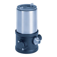
Bürkert 8696 Operating Instructions Manual (190 pages)
Positioner TopControl Basic Electropneumatic Position Controller
Brand:
Bürkert
| Category:
Valve Positioners
| Size: 2 MB
Table of Contents
English
3
Table of Contents
3
1 Operating Instructions
7
Symbols
7
Definition of Term / Abbreviation
7
Positioner Type
7
2 Authorized Use
8
Restrictions
8
3 Basic Safety Instructions
9
4 General Information
10
Contact Address
10
Warranty
10
Trademarks
10
Information on the Internet
10
5 System Description
11
Designated Application Area
11
Function of the Positioner and Combination with Valve Types
11
Features of the Valve Types
12
Model for Control of Third-Party Devices
13
Structure of the Positioner
14
Representation
14
Features
15
Functional Diagram of the Positioner with Single-Acting Actuator
16
Type 8696 Positioner
17
Schematic Representation of the Position Control Type 8696
17
Functions of the Positioner Software
18
Interfaces of the Positioner
20
6 Technical Data
21
Conformity
21
Standards
21
Licenses
21
Operating Conditions
21
Mechanical Data
21
Type
21
Pneumatic Data
22
Type Label
22
Ul Additional Label
23
Electrical Data
23
Factory Settings Of The Positioner
24
7 Control and Display Elements
25
Operating Status
25
Control and Display Elements of the Positioner
25
Configuration of the Keys
26
Function of the Dip Switches
28
Display of the Leds
30
Error Messages
31
Error Messages in MANUAL and AUTOMATIC Operating Statuses
31
Error Messages While the X.TUNE Function Is Running
31
8 Installation
32
Safety Instructions
32
Installation of the Positioner Type 8696 to Process Valves of Series 2103, 2300 and 2301
32
Rotating the Actuator Module for Process Valves Belonging to Series 2300 and 2301
36
9 Pneumatic Installation
38
10 Electrical Installation 24 V DC
40
Electrical Installation With Circular Plug-In Connector
41
Designation of the Contacts Type 8696
41
Connection of the Positioner Type 8696
41
Type
42
11 Start-Up
43
Safety Instructions
43
Specifying The Standard Settings
43
Running the Automatic Adjustment X.TUNE
43
12 Operation and Function
45
Basic Functions
45
Dir.CMD
46
Effective Direction of the Positioner Set-Point Value
46
Cutoff
47
Sealing Function for the Positioner
47
Charact
48
Select the Transfer Characteristic between Input Signal (Position Set-Point Value) and Stroke
48
Input
50
Enter the Input Signal
50
Reset
51
Reset to Factory Settings
51
X.tune
51
Automatic Adjustment of the Positioner to the Relevant Operating Conditions
51
Auxiliary Functions
52
Dir.actuator
52
Effective Direction of the Actuator
52
Splitrange
53
Signal Split Range
53
X.limit
54
Limiting the Mechanical Stroke Range
54
X.time
55
Limiting the Control Speed
55
X.control
56
Parameterization of the Positioner
56
SAFE.POSITION - Definition of the Safe Position
56
Signal.error
57
Configuration of Signal Level Fault Detection
57
Binary.input
57
Activation of the Binary Input
57
OUTPUT (Optional)
58
Configuration of the Analog Output
58
13 Safety End Positions
59
Safety End Positions After Failure Of The Electrical Or Pneumatic Auxiliary Power
59
14 Maintenance
59
15 Disassembly
60
Safety Instructions
60
Disassembly The Positioner
60
16 Accessories
62
Communications Software
62
USB Interface
62
Download
62
17 Packaging and Transport
63
18 Storage
63
19 Disposal
63
Deutsch
65
1 Die Bedienungsanleitung
69
Darstellungsmittel
69
Begriffsdefinition / Abkürzung
69
2 Bestimmungsgemässe Verwendung
70
Beschränkungen
70
3 Grundlegende Sicherheitshinweise
71
4 Allgemeine Hinweise
72
Kontaktadresse
72
Gewährleistung
72
Warenzeichen
72
Informationen IM Internet
72
5 Systembeschreibung
73
Vorgesehener Einsatzbereich
73
Funktion des Positioners und Kombination mit Ventiltypen
73
Merkmale der Ventiltypen
74
Variante zur Ansteuerung von Fremdgeräten
75
Aufbau des Positioners
76
Darstellung
76
Merkmale
77
Funktionsschema des Positioners mit Einfachwirkendem Antrieb
78
Typ 8696 Positioner
79
Schematische Darstellung der Stellungsregelung Typ 8696
79
Funktionen der Positioner-Software
80
Schnittstellen des Positioners
82
6 Technische Daten
83
Konformität
83
Normen
83
Zulassungen
83
Betriebsbedingungen
83
Mechanische Daten
83
Pneumatische Daten
84
Typschild
84
Ul-Zusatzschild
85
Elektrische Daten
85
Werkseinstellungen Des Positioners
86
7 Bedien- und Anzeigeelemente
87
Betriebszustand
87
Bedien- und Anzeigeelemente des Positioners
87
Belegung der Tasten
88
Funktion der Dip-Schalter
90
Anzeige der Leds
92
Fehlermeldungen
93
Fehlermeldungen in den Betriebszuständen HAND und AUTOMATIK
93
Fehlermeldungen bei der Durchführung der Funktion X.TUNE
93
8 Montage
94
Sicherheitshinweise
94
Montage des Positioners Typ 8696 an Prozessventile der Reihe 2103, 2300 und 2301
94
Drehen des Antriebsmoduls bei Prozessventilen der Reihe 2300 und 2301
98
9 Pneumatische Installation
100
10 Elektrische Installation 24 V DC
102
Sicherheitshinweise
102
Elektrische Installation Mit Rundsteckverbinder
103
Bezeichnung der Kontakte Typ 8696
103
Anschluss des Positioners Typ 8696
103
11 Inbetriebnahme
105
Sicherheitshinweise
105
Festlegen Der Grundeinstellungen
105
Ausführen der Automatischen Anpassung X.TUNE
105
12 Bedienung und Funktion
107
Grundfunktionen
107
Dir.CMD
108
Wirkrichtung (Direction) des Positioner-Sollwerts
108
Cutoff
109
Dichtschließfunktion für den Positioner
109
Charact
110
Übertragungskennlinie zwischen Eingangssignal (Stellungs-Sollwert) und Hub
110
Input
112
Eingabe des Eingangssignals
112
Reset./.Factory.reset
113
Rücksetzen auf die Werkseinstellungen
113
X.tune
113
Automatische Anpassung des Positioners an die Jeweiligen Betriebsbedingungen
113
Zusatzfunktionen
114
Dir.actuator
114
Wirkrichtung (Direction) des Stellantriebs
114
Splitrange
115
Signalbereichsaufteilung (Split Range)
115
X.limit
116
Begrenzung des Mechanischen Hubbereichs
116
X.time
117
Begrenzung der Stellgeschwindigkeit
117
X.control
118
Parametrierung des Positioners
118
SAFE.POSITION - Definition der Sicherheitsstellung
118
Signal.error
119
Konfiguration Fehlererkennung Signalpegel
119
Binary.input
119
Aktivierung des Binäreingangs
119
OUTPUT (Option)
120
Konfigurierung des Analogen Ausgangs
120
13 Sicherheitsendlagen
121
Sicherheitsendlagen Nach Ausfall Der Elektrischen Bzw. Pneumatischen Hilfsenergie
121
14 Wartung
121
15 Demontage
122
Sicherheitshinweise
122
Demontage Positioner
122
16 Zubehör
124
Kommunikationssoftware
124
USB Schnittstelle
124
Download
124
17 Verpackung, Transport
125
18 Lagerung
125
19 Entsorgung
125
Français
127
1 A Propos de E Manuel
131
Moyens de Représentation
131
Définition du Terme / Abréviation
131
2 Utilisation Conforme
132
Restrictions
132
3 Consignes de Sécurité Fondamentales
133
4 Indications Générales
134
Adresse
134
Garantie Légale
134
Marques Déposées
134
Informations Sur Internet
134
5 Description du Système
135
Utilisation Prévue
135
Fonction du Positionneur Et Association Avec Les Types de Vanne
135
Caractéristiques des Types de Vanne
136
Variante de Commande des Appareils Étrangers
137
Structure du Positionneur
138
Représentation
138
Caractéristiques
139
Schéma Fonctionnel du Positionneur Avec Actionneur Simple Effet
140
Positionneur Type 8696
141
Représentation Schématique de la Régulation de Position du Type 8696
141
Fonctions du Logiciel du Positionneur
142
Interfaces du Positionneur
144
6 Caractéristiques Techniques
145
Conformité
145
Normes
145
Homologations
145
Conditions D'exploitation
145
Caractéristiques Mécaniques
145
Caractéristiques Pneumatiques
146
Plaque Signalétique
146
Plaque Supplémentaire
147
Caractéristiques Électriques
147
Réglages Usine Du Positionneur
148
7 Éléments de Commande Et D'affichage
149
État de Marche
149
Éléments de Commande Et D'affichage du Positionneur
149
Affectation des Touches
150
Fonction des Interrupteurs Dip
152
Affichage des Led
154
Messages D'erreur
155
Messages D'erreur Dans Les États de Marche MANUEL Et AUTOMATIQUE
155
Messages D'erreur Lors de L'exécution de la Fonction X.TUNE
155
8 Montage
156
Consignes de Sécurité
156
Montage du Positionneur Type 8696 Sur Les Vannes Process des Séries 2103, 2300 Et 2301
156
Rotation du Module Actionneur Pour Les Vannes Process des Séries 2300 Et 2301
160
9 Installation Pneumatique
162
10 Installation Électrique 24 V DC
164
Installation Électrique Avec Connecteur Rond
165
Désignation des Contacts Type 8696
165
Raccordement du Positionneur Type 8696
165
11 Mise en Service
167
Consignes De Sécurité
167
Détermination Des Réglages De Base
167
Exécution de L'adaptation Automatique X.TUNE
167
12 Commande Et Fonctionnement
169
Fonctions De Base
169
Dir.CMD
170
Sens D'action (Direction) de la Valeur de Consigne du Positionneur
170
Cutoff
171
Fonction de Fermeture Étanche du Positionneur
171
Charact
172
Caractéristique de Transfert entre Le Signal D'entrée (Valeur de Consigne de Position) Et la Course
172
Input
174
Saisie du Signal D'entrée
174
Reset
175
Rétablissement des Réglages Usine
175
X.tune
175
Adaptation Automatique du Positionneur Aux Conditions D'exploitation Actuelles
175
Fonctions Supplémentaires
176
Dir.actuator
176
Sens D'action (Direction) de L'actionneur
176
Splitrange
177
Répartition de la Plage du Signal (Split Range)
177
X.limit
178
Limitation de la Course Mécanique
178
X.time
179
Limitation de la Vitesse de Réglage
179
X.control
180
Paramétrage du Positionneur
180
SAFE.POSITION - Définition de la Position de Sécurité
180
Signal.error
181
Configuration Détection de Défaut du Niveau du Signal
181
Binary.input
181
Activation de L'entrée Binaire
181
OUTPUT (Option)
182
Configuration de la Sortie Analogique
182
13 Positions Finales de Sécurité
183
Positions Finales de Sécurité Après Une Panne D'énergie Auxiliaire Électrique Ou Pneumatique
183
14 Maintenance
183
15 Démontage
184
Consignes De Sécurité
184
Démontage Du Positionneur
184
16 Accessoires
186
Logiciel De Communication
186
Interface USB
186
Téléchargement
186
17 Emballage, Transport
187
18 Stockage
187
19 Élimination
187
Advertisement
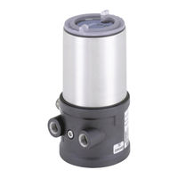
Burkert 8696 Operating Instructions Manual (154 pages)
Electropneumatic Position Controller TopControl Basic
Brand:
Burkert
| Category:
Controller
| Size: 4 MB
Table of Contents
English
3
Table of Contents
3
1 Operating Instructions
7
Definition Of Term "Device
7
Symbols
7
Positioner Type
7
2 Authorized Use
8
Restrictions
8
3 Basic Safety Instructions
9
4 General Information
10
Contact Address
10
Warranty
10
Trademarks
10
Information On The Internet
10
5 System Description
11
Designated Application Area
11
Function Of The Positioner And Combination With Valve Types
11
Features Of The Valve Types
12
Model For Control Of Third-Party Devices
13
Structure Of The Positioner
14
Representation
14
Features
15
Functional Diagram of the Positioner with Single-Acting Actuator
16
Type 8696 Positioner
17
Schematic Representation of the Position Control Type 8696
17
Functions of the Positioner Software
18
Interfaces Of The Positioner
20
6 Technical Data
21
Conformity
21
Standards
21
Operating Conditions
21
Mechanical Data
21
Type
21
Pneumatic Data
22
Type Label
22
Electrical Data
23
Factory Settings Of The Positioner
24
7 Control and Display Elements
25
Operating Status
25
Control And Display Elements Of The Positioner
25
Configuration Of The Keys
26
Function Of The Dip Switches
27
Display Of The Leds
28
Error Messages
29
Error Messages in MANUAL and AUTOMATIC Operating Statuses
29
Error Messages While the X.TUNE Function Is Running
29
8 Installation
30
Safety Instructions
30
Installation Of The Positioner Type 8696 To Process Valves Of Series 2103, 2300 And 2301
30
Rotating The Actuator Module For Process Valves Belonging To Series 2300 And 2301
34
9 Fluid Installation
36
Safety Instructions
36
Installing The Process Valve
36
Pneumatic Connection Of The Positioner
37
10 Electrical Installation 24 V DC
38
Electrical Installation With Circular Plug-In Connector
39
Designation of the Contacts Type 8696
39
Connection of the Positioner Type 8696
39
11 Start-Up
41
Safety Instructions
41
Specifying The Standard Settings
41
Running the Automatic Adjustment X.TUNE
42
12 Operation and Function
43
Basic Functions
43
Dir.CMD
44
Effective Direction of the Positioner Set-Point Value
44
Cutoff
45
Sealing Function for the Positioner
45
CUTOFF Sealing Function for the Positioner
45
Charact
46
Select the Transfer Characteristic between Input Signal (Position Set-Point Value) and Stroke
46
Auxiliary Functions
47
13 Safety Positions
48
Safety Positions After Failure Of The Electrical Or Pneumatic Auxiliary Power
48
14 Maintenance
48
15 Disassembly
49
Safety Instructions
49
Disassembly The Positioner
49
16 Accessories
51
Communications Software (Pc Software Based On Fdt/Dtm Technology)
51
Pactware 3.6
51
USB Interface
51
Download
51
17 Packaging and Transport
52
18 Storage
52
19 Disposal
52
Deutsch
53
1 Die Bedienungsanleitung
57
Begriffsdefinition Gerät
57
Darstellungsmittel
57
2 Bestimmungsgemässe Verwendung
58
Beschränkungen
58
3 Grundlegende Sicherheitshinweise
59
4 Allgemeine Hinweise
60
Kontaktadresse
60
Gewährleistung
60
Warenzeichen
60
Informationen IM Internet
60
5 Systembeschreibung
61
Vorgesehener Einsatzbereich
61
Funktion Des Positioners Und Kombination Mit Ventiltypen
61
Merkmale Der Ventiltypen
62
Variante Zur Ansteuerung Von Fremdgeräten
63
Aufbau Des Positioners
64
Darstellung
64
Merkmale
65
Funktionsschema des Positioners mit Einfachwirkendem Antrieb
66
Typ 8696 Positioner
67
Schematische Darstellung der Stellungsregelung Typ 8696
67
Funktionen der Positioner-Software
68
Schnittstellen Des Positioners
70
6 Technische Daten
71
Konformität
71
Normen
71
Betriebsbedingungen
71
Mechanische Daten
71
Pneumatische Daten
72
Typschild
72
Elektrische Daten
73
Werkseinstellungen Des Positioners
74
7 Bedien- und Anzeigeelemente
75
Betriebszustand
75
Bedien- Und Anzeigeelemente Des Positioners
75
Belegung Der Tasten
76
Funktion Der Dip-Schalter
77
Anzeige Der Leds
78
Fehlermeldungen
79
Fehlermeldungen in den Betriebszuständen HAND und AUTOMATIK
79
Fehlermeldungen bei der Durchführung der Funktion X.TUNE
79
8 Montage
80
Sicherheitshinweise
80
Montage Des Positioners Typ 8696 An Prozessventile Der Reihe 2103, 2300 Und 2301
80
Drehen Des Antriebsmoduls Bei Prozessventilen Der Reihe 2300 Und 2301
84
9 Fluidische Installation
86
Sicherheitshinweise
86
Installation Des Prozessventils
86
Pneumatischer Anschluss Des Positioners
87
10 Elektrische Installation 24 V DC
88
Sicherheitshinweise
88
Elektrische Installation Mit Rundsteckverbinder
89
Bezeichnung der Kontakte Typ 8696
89
Anschluss des Positioners Typ 8696
89
11 Inbetriebnahme
91
Sicherheitshinweise
91
Festlegen Der Grundeinstellungen
91
Ausführen der Automatischen Anpassung X.TUNE
92
12 Bedienung und Funktion
93
Grundfunktionen
93
Charact
93
DIR.CMD - Wirkrichtung (Direction) des Positioner-Sollwertes
94
CUTOFF - Dichtschließfunktion für den Positioner
95
Übertragungskennlinie zwischen Eingangssignal (Stellungs-Sollwert) und Hub
96
Zusatzfunktionen
97
13 Sicherheitsstellungen
98
Sicherheitsstellungen Nach Ausfall Der Elektrischen Bzw. Pneumatischen Hilfsenergie
98
14 Wartung
98
15 Demontage
99
Sicherheitshinweise
99
Demontage Positioner
99
16 Zubehör
101
Kommunikationssoftware (Pc-Software Auf Fdt/Dtm Technologie)
101
Pactware 3.6
101
USB Schnittstelle
101
Download
101
17 Verpackung, Transport
102
18 Lagerung
102
19 Entsorgung
102
Français
103
1 A Propos de E Manuel
107
Définition Du Terme « Appareil
107
Moyens De Représentation
107
2 Utilisation Conforme
108
Restrictions
108
3 Consignes de Sécurité Fondamentales
109
4 Indications Générales
110
Informations Sur Internet
110
5 Description du Système
111
Utilisation Prévue
111
Fonction Du Positionneur Et Association Avec Les Types De Vanne
111
Caractéristiques Des Types De Vanne
112
Variante De Commande Des Appareils Étrangers
113
Structure Du Positionneur
114
Représentation
114
Caractéristiques
115
Schéma Fonctionnel du Positionneur Avec Actionneur Simple Effet
116
Positionneur Type 8696
117
Représentation Schématique de la Régulation de Position du Type 8696
117
Fonctions du Logiciel du Positionneur
118
Interfaces Du Positionneur
120
6 Caractéristiques Techniques
121
Conformité
121
Normes
121
Conditions D'exploitation
121
Caractéristiques Mécaniques
121
Caractéristiques Pneumatiques
122
Étiquette
122
Caractéristiques Électriques
123
Réglages Usine Du Positionneur
124
7 Eléments de Commande Et D'affichage
125
Etat De Marche
125
Eléments De Commande Et D'affichage Du Positionneur
125
Affectation Des Touches
126
Fonction Des Interrupteurs Dip
127
Affichage Des Led
128
Messages D'erreur
129
Messages D'erreur Dans Les États de Marche MANUEL Et AUTOMATIQUE
129
Messages D'erreur Lors de L'exécution de la Fonction X.TUNE
129
8 Montage
130
Consignes De Sécurité
130
Montage du Positionneur Type 8696 Sur Les Vannes Process des Séries 2103, 2300 Et 2301
130
Rotation Du Module Actionneur Pour Les Vannes Process Des Séries 2300 Et 2301
134
9 Installation Fluidique
136
Consignes De Sécurité
136
Installation De La Vanne Process
136
Raccordement Pneumatique Du Positionneur
137
10 Installation Électrique 24 V DC
138
Installation Électrique Avec Connecteur Rond
139
Désignation des Contacts Type 8696
139
Raccordement du Positionneur Type 8696
139
11 Mise en Service
141
Consignes De Sécurité
141
Détermination Des Réglages De Base
141
Exécution de L'adaptation Automatique X.TUNE
142
12 Commande Et Fonctionnement
143
Fonctions De Base
143
Dir.CMD
144
Sens D'action (Direction) de la Valeur de Consigne du Positionneur
144
Cutoff
145
Fonction de Fermeture Étanche du Positionneur
145
Charact
146
Caractéristique de Transfert entre Le Signal D'entrée (Valeur de Consigne de Position) Et la Course
146
Fonctions Supplémentaires
147
13 Positions de Sécurité
148
Positions De Sécurité Après Une Panne D'énergie Auxiliaire Électrique Ou Pneumatique
148
14 Maintenance
148
15 Démontage
149
Consignes De Sécurité
149
Démontage Du Positionneur
149
16 Accessoires
151
Logiciel De Communication (Logiciel Pc Sur Technologie Fdt/Dtm)
151
Pactware 3.6
151
Interface USB
151
Téléchargement
151
17 Emballage, Transport
152
18 Stockage
152
19 Elimination
152
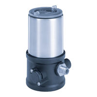
Burkert 8696 Operating Instructions Manual (75 pages)
Positioner Top Control Basic, Electropneumatic Position Controller
Brand:
Burkert
| Category:
Controller
| Size: 1 MB
Table of Contents
Table of Contents
3
1 About These Instructions
7
Symbols
7
Definition of Terms
7
2 Intended Use
8
3 Basic Safety Instructions
9
4 General Information
10
Contact Address
10
Warranty
10
Trademarks
10
Information on the Internet
10
5 System Description
11
Designated Application Area
11
Function of the Positioner and Combination with Valve Types
11
Features of the Valve Types
12
Model for Control of Third-Party Devices
13
Structure of the Positioner
14
Representation
14
Features
15
Functional Diagram of the Positioner with Single-Acting Actuator
16
Type 8696 Positioner
17
Schematic Representation of the Position Control Type 8696
17
Functions of the Positioner Software
18
Interfaces of the Positioner
20
6 Technical Data
21
Conformity
21
Standards
21
Licenses
21
Operating Conditions
21
Mechanical Data
22
Pneumatic Data
22
Type Label
22
UL Additional Label
23
Electrical Data
23
Electrical Data, Without Fieldbus Communication
23
Electrical Data, IO-Link
24
Electrical Data, Büs
24
Factory Settings Of The Positioner
25
7 Control and Display Elements
26
Operating State
26
Control and Display Elements of the Positioner
27
Configuration of the Buttons
28
Display of the Leds
30
Cutoff LED
30
Manual LED
30
Charact LED
30
Status Indicator
31
Error Messages
33
Messages for Device Status "Out of Specification
33
Messages: Actuator Moves to Safety Position
33
8 Installation
35
Safety Instructions
35
Installation of the Positioner Type 8696 to Process Valves of Series 2103, 2300 and 2301
35
Rotating the Actuator Module for Process Valves Belonging to Series 2300 and 2301
39
9 Pneumatic Installation
41
10 Electrical Installation
43
Electrical Installation Without Fieldbus Communication
44
Electrical Installation, Io-Link
46
Electrical Installation, Büs
46
11 Start-Up
47
Safety Instructions
47
Specifying The Standard Settings
47
Running the Automatic Adjustment X.TUNE
47
Setting With Bürkert Communicator
49
Connecting IO-Link Device with Bürkert Communicator
49
Connecting Büs Device with Bürkert Communicator
50
12 Io-Link
51
Information, Io-Link
51
Technical Specifications, Io-Link
51
Configuration of the Fieldbus
51
13 Büs
52
Information, Büs
52
Configuration Of The Fieldbus
52
14 Operation and Function
53
Basic Functions
53
Dir.CMD
55
Reversal Of The Effective Direction Of The Positioner Set-Point Value
55
Cutoff
56
Sealing Function for the Positioner
56
Charact
57
Characteristic Correction Between Input Signal (Position Set-Point Value) And Stroke
57
Input
59
Enter The Standard Signal (Only Variant Without Fieldbus Communication)
59
Reset
60
Reset to Factory Settings
60
X.tune
60
Automatic Adjustment of the Positioner to the Relevant Operating Conditions
60
Auxiliary Functions
61
Dir.act
62
Reversal Of The Effective Direction Of The Actuator
62
Spltrng
63
Signal Split Range
63
X.LIMIT - Stroke Limit
64
X.time
65
Limit Actuating Time
65
Control Parameters of the Positioner
66
Safpos
66
Definition Of The Safe Position
66
Sig.error
67
Configuration of Cable Break Detection (Only for Variant Without Fieldbus Communication)
67
BINARY.IN (Variant)
67
Configuration Of The Digital Input (Only For Variant Without Fieldbus Communication)
67
OUTPUT (Variant)
68
Configuration of the Analog Output (Only for Variant Without Fieldbus Communication)
68
14.2.10 Setting the LED Mode, Device Status
68
15 Safety End Positions
69
Safety End Positions After Failure Of The Electrical Or Pneumatic Auxiliary Power
69
16 Maintenance
69
17 Disassembly
70
Safety Instructions
70
Disassembly The Positioner
70
18 Accessories
72
Communications Software
72
19 Transportation, Storage, Disposal
73
Advertisement
Burkert 8696 Quick Start Manual (30 pages)
Electropneumatic Position Controller
Brand:
Burkert
| Category:
Controller
| Size: 1 MB
Table of Contents
Table of Contents
3
About These Instructions
4
Symbols
4
Definition of Terms
4
Authorized Use
5
Basic Safety Instructions
5
General Information
6
Contact Address
6
Warranty
6
Information on the Internet
6
System Description
7
Structure and Function
7
Model for Control of Third-Party Devices
8
Technical Data
9
Standards and Guidelines
9
Licenses
9
Operating Conditions
9
Mechanical Data
10
Type Labels
10
Pneumatic Data
10
Electrical Data
11
Factory Settings
12
Installation
12
Safety Instructions
12
Installation of the Positioner on Process Valves of Series 2103 and 23Xx
13
Pneumatic Installation
14
Electrical Installation
15
Safety Instructions
15
Electrical Installation Without Fieldbus Communication
15
Electrical Installation, IO-Link
17
Electrical Installation, Büs
17
Start-Up
18
Safety Instructions
18
10.2 Automatic Adjustment X.TUNE
18
10.3 Setting with Bürkert Communicator
19
10.4 IO-Link
21
10.5 Büs
21
Control and Display Elements
22
Operating State
23
Functions Of The Buttons
23
Display Of The Leds
24
Safety End Positions
27
Accessories
27
Communications Software
28
Packaging, Transport, Storage
28
Burkert 8696 Quick Start Manual (24 pages)
Brand:
Burkert
| Category:
Controller
| Size: 1 MB
Table of Contents
Table of Contents
3
1 Quickstart
4
Definition of Term / Abbreviation
4
Symbols
4
2 Authorized Use
5
3 Basic Safety Instructions
5
4 General Information
7
Contact Address
7
Warranty
7
Information on the Internet
7
5 System Description
7
Structure and Function
7
Model for Control of Third-Party Devices
8
6 Technical Data
9
Conformity
9
Standards
9
Licenses
9
Operating Conditions
9
Mechanical Data
10
Type Labels
10
Pneumatic Data
11
Electrical Data
11
Factory Settings of the Positioner
12
7 Installation
12
Safety Instructions
12
Installation of the Positioner on Process Valves of Series 2103 and 23Xx
13
8 Pneumatic Installation
14
9 Electrical Installation
15
Safety Instructions
15
Electrical Installation with Circular Plug-In Connector
15
10 Start-Up
16
Safety Instructions
16
10.2 Automatic Adjustment X.TUNE
16
10.3 Control and Display Elements
18
11 Safety Positions
21
12 Accessories
22
Communications Software
22
12.2 USB Interface
22
12.3 Download
22
Packaging, Transport, Storage
22
Advertisement
Related Products
Burkert 8692
Burkert 8693
Burkert 8696 REV.2
Burkert 8691 REV.3
Burkert 8681
Burkert 8644 AirLINE
Burkert 8623-B
Burkert 8624
Burkert 8624-B
Burkert 8605 KK
Burkert Categories
Control Unit
Controller
Measuring Instruments
Transmitter
Accessories
More Burkert Manuals
Login
Sign In
OR
Sign in with Facebook
Sign in with Google
Upload manual
Upload from disk
Upload from URL