
Related Manuals for Samson TROVIS 5432


Summary of Contents for Samson TROVIS 5432
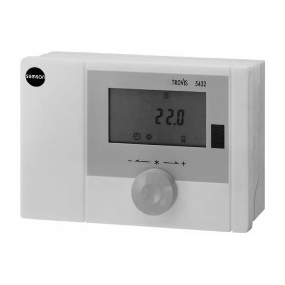
- Page 1 Automation System TROVIS 5400 Heating and District Heating Controller TROVIS 5432 Fig. 1 ⋅ Type 5432 Mounting and operating instructions EB 5432-1 EN Firmware Version 1.00 ® Edition September 2001 Electronics from SAMSON...
-
Page 2: Table Of Contents
Contents Contents Page Notes for the user ......5 Operation ........6 Control levels . - Page 3 Inhaltsverzeichnis 7.11 Pump seizure protection ......7.12 Defective sensors ......7.13 Actual values .
- Page 4 Safety instructions Assembly, start-up and operation of the device may only be performed by trained and experienced personnel familiar with this product. According to these mounting and operating instructions, trained personnel is referred to persons who are able to judge the work they are assigned to and recognize possible dangers due to their specialized training, their know- ledge and experience as well as their knowledge of the relevant standards.
-
Page 5: Notes For The User
Notes for the user 1. Notes for the user The controller is ready for operation with its factory (default) settings for temperatures and time schedules. On start-up, after switching on the power supply, you must enter the current time and date. Refer to chapter 3 for further information about how to proceed. -
Page 6: Operation
Operation 2. Operation Just one control knob is needed to operate the controller. Turning the knob lets you change the current reference value or set point or lets you select parameters and temperatures. Pressing the knob for three seconds lets you switch over from one control level to the next. Pressing the knob briefly lets you activate a parameter to change it or lets you acknow- ledge a changed parameter. - Page 7 Operation User level Display level Installation level Reference value for room temperature or Time Function blocks set point and Times-of-use Parameters actual value for Reference values and Temperature values flow temperature set points Short-term change to reference value or set point See quick guide at the back of this booklet ! Counterclockwise Press...
-
Page 8: Start-Up
Start-up 3. Start-up The controller is ready for use with its factory (default) settings after it has been installed and the power supply has been connected. To start up, switch on the power supply. Setting the current time and date When the controller is started up for the first time or the controller is disconnected from the power supply for more than 72 hours, the default setting with blinking time ap-... -
Page 9: Setting Options On The Display Level
Setting options on the display level 4. Setting options on the display level The display level provides the following setting options that are only effective for a certain time: If the current room temperature is too warm or too cold, you can override the controller setting. -
Page 10: Holiday Mode
Setting options on the display level Alternatively, you can wait three seconds until the display stops blinking. The party mode is activated. The party mode remains effective until a different reference value or set point is entered. Even after a power failure, the party mode remains effective. If you want to end the party mode, turn the control knob counterclockwise one position. -
Page 11: Setting Options On The User Level
Setting options on the user level 5. Setting options on the user level The controller is set to the display level. The controller is set to the operating mode "Weather-compensated control" as default. The room reference value appears in the display. If the operating mode has been changed to "Fixed set point control", the set point appears on the left-hand side and the actual value of the flow temperature on the right-hand side... -
Page 12: Setting The Current Time And Date
Setting options on the user level 5.1 Setting the current time and date A time appears in the display or, if the controller has not been in operation for the past 72 hours, the default setting 10:00 appears in the display. You only need to change the time and date, if they are different from the time and date en- tered during start-up. -
Page 13: Setting The Times-Of-Use
Setting options on the user level 5.2 Setting the times-of-use You can enter three time periods for the time-controlled operation for every day of the week, during which the heating system runs in rated operation. The default setting is a daily rated operation with just one period of time-of-use from 7:00 to 22:00 hrs. - Page 14 Setting options on the user level Entering a weekly schedule Turn the control knob clockwise one position. The current time-of-use appears in the display. Press the control knob. The time period symbol starts to blink. Turn the control knob until the numbers for all days 1 to 7 in boxes appear at the top of the display and the first time period 1 appears.
- Page 15 Setting options on the user level After you have entered the last time-of-use period, the time period symbol still blinks. Turn the control knob clockwise one position further. End appears in the display. Press the control knob to acknowledge the settings. The stop and start times for the time-of-use period 1 of the current day (today) appear in the display.
-
Page 16: Reading The Set Times-Of-Use
Setting options on the user level After entering the last time-of-use period, the time period symbol still blinks in the display, turn the control knob to access the next day and set like- wise the required time-of-use periods. Repeat the setting procedure for all of the following days. After entering the last time-of-use period, the time period symbol still blinks in the display, turn the control knob clockwise or counterclockwise until... -
Page 17: Setting The Reference Value For Room Temperature Or The Flow Temperature Set Point For Rated And Reduced Operation
Setting options on the user level 5.3 Setting the reference value for room temperature or the flow temperature set point for rated and reduced operation If you are not on the user level, press the control knob for three seconds. At first, the time appears in the display. -
Page 18: Viewing The Outdoor Temperature
Setting options on the user level In the operating mode"Fixed set point control", the flow temperature set point for reduced operation (time of non- use) appears in the display. The default value is 50.0 °C. If you want to change the currently displayed value: Press the control knob. -
Page 19: Configuration And Parameterization
Configuration and parameterization 6. Configuration and parameterization The controller configuration und parameterization are entered on the installation level. After accessing the installation level, the function blocks F1 to F6 appear first of all, followed by the parameters P1 to P15 and finally the measured temperatures t1 to t4. You can select function blocks, parameters and measured temperatures you require by turn- ing the control knob. -
Page 20: Setting The Function Blocks And Parameters
Configuration and parameterization 6.2 Setting the function blocks and parameters Note: When you set certain function blocks, the associated parameter needs to be set, too. The function blocks (F) and parameters (P) are listed in sequence. Further details about the functions are described in chapter 7. - Page 21 Configuration and parameterization Min. flow temperature 30.0 0.0...130.0 °C (Chap. 7.4) Max. flow temperature 80.0 20.0...130.0 °C Fixed set point 50.0 20.0...90.0 °C (Chap. 7.5) Return flow temperature Setting with code number Drinking water set point 55.0 20.0...90.0 °C (Chap. 7.6) Kp Return flow temp.
-
Page 22: Description Of The Controller Functions
Description of the controller functions 7. Description of the controller functions The TROVIS 5432 Heating and District Heating Controller is designed to control the flow tem- perature in heating systems. The control is either weather-compensated using an outdoor or flow sensor, or based on a fixed set point for the flow temperature just using one flow sen- sor. -
Page 23: Operating Modes
Description of the controller functions 7.1 Operating modes 7.1.1 Weather-compensated control Set the function block F1 to1 = ON, and set the parameter P1= Heating characteristic gra- dient and P2 = Level. Sensors AS and VS for outdoor and flow temperatures are required. When the weather-compensated control is active, the reference value for room temperature appears in the display. -
Page 24: Fixed Set Point Control
Description of the controller functions Flow temperature Flow temperature ˚ ˚ 3.2 2.9 2.6 ˚ ˚ 20 16 12 8 20 16 12 8 0 -4 -8 -12 -16 -20 0 -4 -8 -12 -16 -20 Outdoor temperature Fig. 4 ⋅ Heating characteristic gradient and level displacement Level: In addition to the gradient, the level of the heating characteristic can be lowered or raised by ±30°C using the parameter P2. -
Page 25: Delayed Outdoor Temperature Adaptation
Description of the controller functions 7.2 Delayed outdoor temperature adaptation Set the function block F3 to 1 = ON and P7 = Delayed outdoor temperature adaptation A sensor AS for the outdoor temperature is required. This function accounts for the fact that a building stores heat. Usually, short-term variations in outdoor temperature do not affect the room temperature. -
Page 26: On/Off Control
Description of the controller functions 7.3.2 On/off control Set F4 to 0 = OFF and P13 = Differential gap, P14 = Minimum activation time and P15 = Mi- nimum deactivation time. The controller issues a control signal OPEN (+) and CLOSE (-). The switching characteristic is determined by selecting the differential gap. -
Page 27: Limitation Of The Return Flow Temperature
Description of the controller functions 7.5 Limitation of the return flow temperature Setting with P5 = Fixed set point of return flow temperature, P8 = Kp Gain and P9 = Tn Reset time. This function is automatically activated when the sensor RüS for the return flow temperature is connected. -
Page 28: Subfloor Drying
Description of the controller functions 7.7 Subfloor drying Set F6 to 1 = ON Anhydrite and cement plaster floors (wet screed) must be heated prior to laying a floorcover- ing (DIN norm 4725, Part 4). The first heating up starts with a flow temperature of 25 °C. This temperature is kept constant for three days. -
Page 29: Manual Operation
Description of the controller functions 7.10 Manual operation Set F2 to 1 = ON Manual operation is carried out as stipulated in DIN EN 12098-1. The circulation pump is activated. The controller does not issue a control signal in either on/off control or three-step control for the heating circuit’s control valve. -
Page 30: Defective Sensors
Description of the controller functions 7.12 Defective sensors In the event of a defective sensor, the malfunction symbol starts to blink in the display. Defective or missing sensor: For three-step control: The control valve is closed completely and then opened to 1/3 over the control valve transit time. -
Page 31: Installation And Electrical Connections
Installation and electrical connections 8. Installation and electrical connections 8.1 Installing the controller The controller is made up of the casing section and the base. The casing contains the elec- tronic components, the LC display and the control knob. The base contains the terminals. Important: The casing section must be separated from the base before the controller can be installed and wired. -
Page 32: Electrical Connections
8.2.1 Installation recommendations These recommendations are intended as a guide to help you to set up the heating system op- timally and to increase its efficiency. SAMSON assumes no responsibility or liability for any incorrect specifications. Electric cables Use a separate cable for the power supply (230 VAC, 50 Hz) to the controller. -
Page 33: Connecting The Controller
Installation and electrical connections Surge protection The following measures must be taken to protect the controller from overvoltage if signal lines are installed outside of buildings or over long distances. The shield of signal lines routed outside of buildings must have current carrying capacity and must be grounded on both sides. -
Page 34: Connecting The Sensors
Installation and electrical connections 8.4 Connecting the sensors Connect cables with a cross-section of min. 2x 0.5 mm to the terminals of the controller. 8.4.1 Pt 1000 sensor values °C –35 –30 –25 –20 –15 –10 –5 862.5 882.2 901.9 921.6 941.2 960.9... -
Page 35: Technical Data
Technical data 9. Technical data Inputs 4 sensor inputs Flow temperature Pt 1000 Outdoor temperature Return flow temperature Drinking water temperature Outputs Control signal y Three-step signal: load: 20 to 250 V AC; 0.3 A AC On/off signal: load: 20 to 250 V AC; 0.3 A AC Binary output 1 output for pump control, non-floating: 230 V AC, 2 A AC (cos ϕ... -
Page 36: Quick Guide
Quick guide Display level User level Installation level F1 Operating mode Reference value Time/date for room temp. F2 Manual operation or set point F3 Delay outdoor temp. adaptation and actual value for flow temperature Heating schedule F4 3-step/on-off control signal F5 Summer/winter time Short-term change Reference value... - Page 37 EB 5432-1 EN...
- Page 38 SAMSON AG ⋅ MESS- UND REGELTECHNIK Weismüllerstraße 3 ⋅ D-60314 Frankfurt am Main ⋅ Germany Phone +49 69 4 00 9-0 ⋅ Fax +49 69 4 00 9-15 07 EB 5432-1 EN Internet: http://www.samson.de...
Need help?
Do you have a question about the TROVIS 5432 and is the answer not in the manual?
Questions and answers