Table of Contents
Advertisement
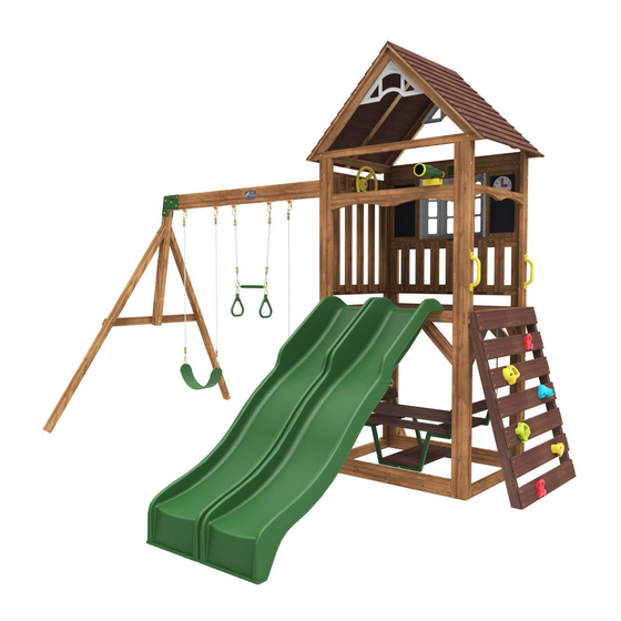
L I N D A L E P L A Y S E T - F 2 9 1 3 0
INSTALLATION AND OPERATING INSTRUCTIONS
WARNING
OBSTACLE FREE SAFETY ZONE - 27' 5/8" x 26' 1-1/2" (8.25m x 7.96m) area requires Protective Surfacing. See page 3.
MAXIMUM VERTICAL FALL HEIGHT -
CAPACITY - 9 Users Maximum, Ages 3 to 10;
Weight Limit 110 lbs. (49.9 kg) per child.
RESIDENTIAL HOME USE ONLY. Not intended for public areas such as schools,
churches, nurseries, day cares or parks.
WARNING. Only for domestic use.
8 .25m
824.5cm
5
27' 5/8"
27'
"
8
4 .24m
424.5cm
1
13'11
"
13'10-3/4"
8
3 .06m
325.6cm
1
10'39/64"
10'8
"
4
10 - 14 Hrs
TWO PERSON
ASSEMBLY
FOR OUTDOOR FAMILY DOMESTIC USE ONLY
To reduce the risk of serious injury or death, you must read and follow these instructions. Keep and refer to
these instructions often and give them to any future owner of this play system. Manufacturer contact information
provided below.
6'4"(1.93m)
7 .96m
796.4cm
1
26'1
"
26' 1-1/2"
2
Cedar Summit by KidKraft
4630 Olin Road
Dallas, TX 75244, United States
customerservice@kidkraft.com
Online Parts Replacement: parts.kidkraft.com
To warranty your product: kidkraft.com/warranty/
Customer Service: 1(800) 933-0771 or (972) 385-0100
KidKraft Netherlands BV
Olympisch Stadion 8
1076 DE Amsterdam, The Netherlands
Europe Customer Service: +31 (0)20 305 8620
europecustomerservice@kidkraft.com
EU Online Parts Replacement: parts.kidkraft.eu
Table of Contents
Warnings And Safe Play Instructions . . . . . pg . 2
Protective Surfacing Guidelines . . . . . . . . pg . 3
Instructions For Proper Maintenance . . . . . pg . 4
About Our Wood – Limited Warranty . . . . . pg . 5
Keys To Assembly Success . . . . . . . . . . . . pg . 6
Part ID . . . . . . . . . . . . . . . . . . . . . . . . . . . . pg . 7
Step-By-Step Instructions . . . . . . . . . . . . pg . 14
9409130
Rev 12/20/2019
Advertisement
Table of Contents

Related Manuals for KidKraft Cedar Summit LINDALE PLAYSET F29130


Summary of Contents for KidKraft Cedar Summit LINDALE PLAYSET F29130
- Page 1 Instructions for Proper Maintenance . . . . . pg . 4 To warranty your product: kidkraft.com/warranty/ About Our Wood – Limited Warranty . . . . . pg . 5 Customer Service: 1(800) 933-0771 or (972) 385-0100 Keys to Assembly Success .
- Page 2 Warnings and Safe Play Instructions CONTINUOUS ADULT SUPERVISION REQUIRED. Most serious injuries and deaths on playground equipment have occurred while children were unsupervised! Our products are designed to meet mandatory and voluntary safety standards. Complying with all warnings and recommendations in these instructions will reduce the risk of serious or fatal injury to children using this play system.
- Page 3 Protective Surfacing - Reducing Risk of Serious Head Injury From Falls One of the most important things you can do to reduce the likelihood of serious head injuries is to install shock-absorbing protective surfacing under and around your play equipment. The protective surfacing should be applied to a depth that is suitable for the equipment height in accordance with ASTM F1292.
- Page 4 Instructions for Proper Maintenance Your Cedar Summit Play System is designed and constructed of quality materials with your child’s safety in mind. As with all outdoor products used by children, it will weather and wear. To maximize the enjoyment, safety and life of your Play Set, it is important that you, the owner, properly maintain it.
- Page 5 10 Year Limited Warranty Cedar Summit by KidKraft warrants that this product is free from defect in materials and workmanship for a period of one year from the original date of purchase. In addition, lumber is warranted for 10 years against structural failure due to rot and insect damage.
- Page 6 Keys to Assembly Success Tools Required • Tape Measure • #1 Phillips, #2 Robertson • Open End Wrench • 3/16” Hex Key • Carpenters Level (1/2” & 9/16”) • 8’ Step Ladder and Screwdriver • Carpenters Square • Ratchet with extension •...
- Page 7 - BOX 1 3589816 3589817 878 .9 34-5/8 878 .9 34-5/8 3589821 3589822 133 .4 3589823 5-1/4” 133 .4 3589824 5-1/4” 133 .4 3589833 5-1/4” 133 .4 3589834 5-1/4” 3589723...
- Page 8 - BOX 1 9885 - 15 .9 x 63 .5 x 849 .8 mm - 3839885 5/8 x 2-1/2 x 33-7/16" 3589725 2613 2201 .9 832613 86-11/16" 2x - 2606 - 23 .8 x 82 .6 x 362 .0 mm - 3832606 2x - 2607 - 31 .8 x 76 .2 x 558 .8 mm - 3832607 15/16 x 3-1/4 x 14-1/4"...
- Page 9 - BOX 2 3589726 3589727 3589728 3589729 3589730 396 .2 15-5/8” 3589724 37589312 37589313...
- Page 10 - BOX 2 9309 9308 1143 x 2286mm 37839314 9327884 If you need to order parts, please order below part # 9308 - 37839308 - Window Panel Left - 1pc 9309 - 37839309 - Window Panel Right -1pc 9327884 - Hinge - 1pc - 52933505 - Truss Screw #8 x 7/8”...
- Page 11 - BOX 2 1143 x 2286mm 37839315 9310 9311 9327884 If you need to order parts, please order below part # 9310 - 37839310 - Panel - 1pc 9311 - 37839311 - Ride Maze Panel Right -1pc 9327884 - Hinge - 1pc - 52933505 - Truss Screw #8 x 7/8”...
- Page 12 Hardware Identification (Actual Size) 12x - FW1 - 1/4" - 51103200 11x - LW2 - 5/16" - 51303300 8x - TN1 - 1/4" 54503200 19x - TN2 - 5/16"- 54503300 6 .4mm 7 .9mm 6 .4mm 7 .9mm 18x - LW1 - 1/4" - 51303200 6 .4mm 71x - FW2 - 5/16"...
- Page 13 Part Identification (Reduced Part Size) 1x - 3329130 (6pk) 1x - 3200718 (7pk) 1x - 3320161 2x - 9320130 1x - 9320374 2x - 3320704 1x - 3320255 1x - 3200022 (2pk) 1x - 3759190 1x - 3200145(2pk) 1x - 3720002 2x - 9320131 1x - 3201950 (6pk) 1x - 3205940 (3pk)
- Page 14 • The carton I .D . stamp is located on the end of each carton . The tracking number is located on the KidKraft ID Plaque (9320374) . • Please retain this information for future reference . You will need this information if you contact the Consumer Relations Department .
- Page 15 Step 2 Pre-drill each hole using a 3/16” drill bit for WL5. Hidden 9314 9306 9307 9315 Wood Parts Hardware 16 x 6.4 x 63.5 mm (1/4 x 2-1/2”) 31.8 x 1043 x 3386mm (1-1/4 x 45 x 90”) 31.8 x 914.4 x 2336.8 mm (1-1/4 x 36 x 92”) 9314 9306 31.8 x 914.4 x 2336.8 mm (1-1/4 x 36 x 92”)
- Page 16 Step 3 9813 9813 9813 Wood Parts Hardware 12 x #8 x 63.5 mm (#8 x 2-1/2”) 31.8 x 38.1 x 990.6 mm (1-1/4 x 1-1/2 x 39”) 9813...
- Page 17 Step 4 9814 15 .9mm 5/8” WB10 9814 9814 WB10 WB10 9814 WB10 WB10 Hardware Wood Parts Hardware 38.1 x 38.1 x 1141 mm (1-1/2 x 1-1/2 x 44-15/16”) 7.9mm x 66.6 mm (5/16 x 2-5/8”)(FW2, TN2) 9814 WB10 #12 x 50.8mm (#12 x 2”)
- Page 18 Step 5 9817 9816 9817 Wood Parts Hardware 15.9 x 114.3 x 848.8 mm (5/8 x 4-1/2 x 33-7/16”) #8 x 35mm (#8 x 1-3/8”) 9816 15.9 x 88.9 x 848.8 mm (5/8 x 3-1/2 x 33-7/16”) 9817...
- Page 19 Step 6 9816 9815 9816 9817 9815 9816 Wood Parts Hardware 38.1 x 76.2 x 1143 mm (1-1/2 X 3” X 45”) #8 x 35mm (#8 x 1-3/8”) 9815 #8 x 76.2mm (#8 x 3”)
- Page 20 Step 7 9816 9816 9816 Wood Parts Hardware 15.9 x 114.3 x 848.8 mm (5/8 X 4-1/2 X 33-7/16”) 48 x #8 x 35mm (#8 x 1-3/8”) 9816...
- Page 21 Step 8 9812 9812 9812 9812 9812 9812 Wood Parts Hardware 16 x #8 x 76.2mm (#8 x 3”) 31.8 x 76.2 x 387.4 mm (1-1/4 X 3 X 15-1/4”) 9812...
- Page 22 Step 9 IMPORTANT! Follow hole pattern 9834 Pre-drill holes using a 1/8” drill bit. 9833 9822 Do not attach Put aside until Center first board Step 13 and evenly space remaining 9823 9824 9833 9834 9833 9822 9834 9824 9822 Hardware Wood Parts 38.1 x 63.5 x 1244.6 mm (1-1/2 x 2-1/2 x 49”)
- Page 23 Step 10 Note: Make sure all hardware is Note: Make sure all hardware is used to properly secure each rock. used to properly secure each rock. 9320197RD 9320081BL 9320081YL 9320082YL 9320197RD 9320082LG Hardware Other Parts 9320197RD 9320082YL 10 x 7.9mm x 32 mm (5/16 x 1-1/4”) (FW0, LW1, BN1) 9320082LG 9320081YL #8 x 25.4 mm (#8 x 1”)
- Page 24 Step 11 9821 9821 Hardware Wood Parts 15.9 x 76.2 x 914.4 mm (5/8 x 3 x 36”) #8 x 35mm (#8 x 1-3/8”) 9821...
- Page 25 Step 12 Install TN1 (will be used in Step 46) Hardware 4 x TN1...
- Page 26 Step 13 Hardware #8 x 35 mm (#8 x 1-3/8”)
- Page 27 Step 14 Pre-drill holes using a 1/8” drill bit. 9823 Hardware #12 x 50.8mm (#12 x 2”)
- Page 28 Step 15 Center 9820 board and evenly space the rest Alignment hole 9819 9819 9819 9819 9820 9819 Beveled edge faces out Alignment hole 9819 9819 9820 9819 9819 Center 9820 board and evenly space the rest Wood Parts Hardware 15.9 x 76.2 x 878.9 mm (5/8 x 3 x 34-5/8”) 20 x #8 x 34.9 mm (#8 x 1-3/8”)
- Page 29 Step 16 Center first board and evenly space the rest 9818 Beveled edge faces out 9818 9818 9818 9818 9818 9818 9818 9818 9818 9818 9818 9818 9818 Wood Parts Hardware 15.9 x 76.2 x 396.2 mm (5/8 x 3 x 15-5/8”) 28 x #8 x 34.9 mm (#8 x 1-3/8”) 9818...
- Page 30 Step 17 Install TN2 (will be used in Step 25) Hardware 1 x TN2...
- Page 31 Step 18 Notice Angle Orientation 3201950 2614 Wood Parts Hardware Other Parts 76.2 x 133.4 x 2235.2 mm (3” x 5-1/4” x 88”) 2614 3201950 12 x 7.9mm x 139.7 mm (5/16 x 5-1/2”) (LN2, 2 x FW2)
- Page 32 Step 19 IT IS IMPORTANT THAT THIS BOLT IS ATTACHED. IT WILL MINIMIZE CHECKING OF WOOD. Caution: The Spring Loaded Quick Link must be attached to the Heavy Duty Swing Hanger in the closed position. Hardware 7.9mm x 76.2mm (5/16 x3”)( FW2 , TN2 )
- Page 33 Step 20 9320358 3200145 3200145 Hardware Other Parts 7.9 x 95 mm (5/16 x 3-3/4”) (2 x FW2, LN2) 3200145 9320358 #6 x 25.4 mm (#6 x 1”)
- Page 34 Step 21 2613 2615 2613 Wood Parts Hardware 50.8 x 76.2 x 2201.9 mm (2 x 3 x 86-11/16”) 7.9 x 139.7 mm (5/16 x 5-1/2”) (LW2, FW2, TN2) 2613 76.2 x 76.2 x 1294.3 mm (3 x 3 x 50-15/16”) 2615...
- Page 35 Step 22 IT IS IMPORTANT THAT THESE BOLTS ARE ATTACHED. THEY WILL MINIMIZE CHECKING OF WOOD. 2616 2616 Wood Parts Hardware 23.8 x 82.6 x 1181.1mm (15/16 x 3-1/4 x 46-1/2”) 7.9mm x 101.6mm (5/16 x 4”) (LW2, FW2, TN2) 2616 7.9mm x 76.2mm (5/16 x 3”) (LW2, FW2, TN2)
- Page 36 Step 23 9200143 G21 G21 9200144 Hardware Other Parts 7.9 x 95 mm (5/16 x 3-3/4”) (LN2, 2 x FW2) 9200143 9200144...
- Page 37 Step 24 Hardware 7.9 x 44.5 mm (5/16 x 1-3/4”) (LN2, 2 x FW2)
- Page 38 Step 25 3320255 Note: T-Nut previously installed in Step 17. Hardware Other Parts 7.9mm x 76.2mm (5/16 x 3”) (FW2) 3320255...
- Page 39 Step 26 x 2 9826 9826 9825 Wood Parts Hardware 31.8 x 50.8 x 1371.6 mm (1-1/4 x 2 x 54”) #8 x 64mm (#8 x 2-1/2”) 9825 31.8 x 50.8 x 898.1 mm (1-1/4 x 2 x 35-3/8”) 9826...
- Page 40 Step 27 9312 3205940 9313 9312 3205940 9313 Wood Parts Hardware Other Parts 28.6 x 952.5 x 1014.4 mm (1-1/8 x 37-1/2 x 39-15/16”) #8 x 22.2mm (#8 x 7/8”) 9312 1 x 3205940 28.6 x 952.5 x 1008 mm (1-1/8 x 37-1/2 x 39-11/16”) 9313...
- Page 41 Step 28 AI-35 Gables should be flush to S11 X 8 inside edges on both sides gable flush to inside ed 9313 9312 9826 (Hidden) 9312 9313 9826 Hardware #8 x 63.5 mm (#8 x 2-1/2”)
- Page 42 Step 29 Hardware 7.9mm x 76.2mm (5/16 x3”)(LW2, FW2, TN2 ) #8 x 76.2mm (#8 x 3”)
- Page 43 Step 30 9330504 9330504 9330504 Hardware Other Parts #8 x 22.2mm (#8 x 7/8”) 2 x 9330504...
- Page 44 Step 31 3320704 3320704 3320704 Hardware Other Parts 12 x #8 x 22.2mm (#8 x 7/8”) 2 x 3320704...
- Page 45 Step 32 3320161 3320161 Hardware Other Parts 3320161 #8 x 35mm (#8 x 1-3/8”)
- Page 46 Step 33 Pre-drill each hole using a 1/8” drill bit. 3320240 3320240 (152 .4mm) 6” Hardware Other Parts 6.4 x 35 mm (1/4 x 1-3/8”) (FW1) 3320240...
- Page 47 Step 34 Notice hole orientation 3720002 3799194 9209192 Other Parts 3799194 3720002 9209192...
- Page 48 Step 35 3720002...
- Page 49 Step 36 9729 9729 9730 Notice hole orientation 3799193 Other Parts Wood Parts 3799193 23.8 x 101.6 x 584.8 mm (15/16” x 4” x 23”) 9729 23.8 x 101.6 x 584.8 mm (15/16” x 4” x 23”) 9730...
- Page 50 Step 37 9727 9728 9728 9727 3799193 Wood Parts Other Parts 23.8 x 82.6 x 584.8 mm (15/16” x 3-1/4” x 23”) 3799193 9727 23.8 x 82.6 x 500.2 mm (15/16” x 3-1/4” x 19-11/16”) 9728...
- Page 51 Step 38 9726 9725 3799193 Wood Parts Other Parts 23.8 x 82.6 x 761.2 mm (15/16” x 3-1/4” x 30”) 3799193 9725 23.8 x 82.6 x 592.3 mm (15/16” x 3-1/4” x 23-5/16”) 9726...
- Page 52 Step 39 9723 3799193 9723 Wood Parts Other Parts 23.8 x 82.6 x 905.7 mm (15/16” x 3-1/4” x 35-5/8”) 3799193 9723...
- Page 53 Step 40 3799193 9724 9724 Wood Parts Other Parts 23.8 x 82.6 x 584.8 mm (15/16” x 3-1/4” x 23”) 3799193 9724...
- Page 54 Step 41 3759190 Other Parts 3759190...
- Page 55 Step 42...
- Page 56 Step 43 9725 25 .4 mm 25 .4 mm 1” 1” 9725 9729 9730 9729 Hardware #7 x 15.87mm (#7 x 5/8”) (FW3)
- Page 57 Step 44 9729 63 .5 mm 230 mm 230 mm 63 .5 mm 2-1/2” 9” 9” 2-1/2” Hardware #7 x 15.87mm (#7 x 5/8”) (FW3)
- Page 58 Step 45 9729 63 .5 mm 230 mm 230 mm 63 .5 mm 2-1/2” 9” 9” 2-1/2” Hardware #7 x 15.87mm (#7 x 5/8”) (FW3)
- Page 59 Step 46 3200106 Note: T-Nut previously installed in Step 12. 3200106 Hidden 3200106 Hidden 3200106 3200106 Hardware Other Parts 3200106 6.4mm x 38.1mm (1/4 x 1-1/2”)(LW1, FW1, TN1) 6.4mm x 38.1mm (1/4 x 1-1/2”)(LW1, FW1)
- Page 60 Step 47 Tighten Threaded Quick Link Quick Link using adjustable wrench 3720002 Caution: Threaded Quick Links must be installed with the gate completely down covering the threads and tighten as instructed. 3720002 Quick Link Threaded Quick Links attach Tighten Threaded Link to chat swing and the fort .
- Page 61 Step 48 3720002 Hardware 4 x FW2...
- Page 62 Step 49 Note: Pre-drill all holes using a 1/8” drill bit before installing the S7 screws. 7310149 7310149 Hardware Other Parts #12 x 50.8mm (#12 x 2”) 7310149...
- Page 63 Step 50 3320341 Inside View 3320341 Hardware Other Parts 1 x 3320341 #8 x 22.2mm (#8 x 7/8”) #7 x 16 mm (#7 x 5/8”)
- Page 64 Step 51 Outside View 3320341 Hardware #8 x 22.2mm (#8 x 7/8”)
- Page 65 Step 52 Inside View Hardware #8 x 22.2 mm (#8 x 7/8”) #7 x 16 mm (#7 x 5/8”)
- Page 66 Step 53 Pre-drill hole using a 3/16” drill bit for WL5 2607 2606 2607 2606 2607 2606 Wood Parts Hardware 23.8 x 82.6 x 362 mm (15/16 x 3-1/4 x 14-1/4”) 7.9 x 54 mm (5/16 x 2-1/8”) (FW2, TN2) #8 x 64 mm (#8 x 2-1/2”) 2606 31.8 x 76.2 x 558.8 mm (1-1/4 x 3 x 22”)
- Page 67 Step 54 9885 Hidden 9885 Hardware Wood Parts 15.9 x 63.5 x 849.8 mm (5/8 x 2-1/2 x 33-7/16”) #8 x 34.9 mm (#8 x 1-3/8”) 9885...
- Page 68 Step 55 9502020 9502045 9502045 9320130 European customers receive rope swing instead of chain due to EN71 standards: To be installed as per instructions. 9502020 Caution: Threaded Quick Links must be installed with the gate completely down covering the threads and tighten as instructed.
- Page 69 Step 56 MOVE FORT TO FINAL LOCATION PRIOR TO STAKING FINAL LOCATION MUST BE LEVEL GROUND Warning! To prevent tipping and avoid potential injury, 9290318 stakes must be driven 13”(330mm) into ground. Digging or driving stakes can 13” In be dangerous if you do not Ground check first for under-ground (330mm)
- Page 70 POUR LES ENFANTS DE 3 À 10 ANS D'ÂGE; limite de 110 Livres par enfant. Nombre maximum d’ utilisateurs, installation et d'utilisation; d'autres informations sont disponibles sur: www.KidKraft.com Contact us at: KidKraft Dallas, TX 75244 USA 1-800-933-0771 Tracking Number: Numèro de Suivi:...
- Page 71 NOTES...
- Page 72 Would you recommend the purchase of our products to friends and family? Comments: MAIL TO: Fill out your registration card online at KidKraft www.cedarsummitplay.com/ 4630 Olin Road registration Dallas, TX 75244 United States Cedar Summit by KidKraft would like to say Attention: Customer Service Thank You for your time and feedback.
Need help?
Do you have a question about the Cedar Summit LINDALE PLAYSET F29130 and is the answer not in the manual?
Questions and answers