Table of Contents
Advertisement
Quick Links
Advertisement
Table of Contents

Related Manuals for Satel GSM-4S


Summary of Contents for Satel GSM-4S
- Page 1 ® COMMUNICATION MODULE GSM-4S USER MANUAL Program version 4.11 gsm4_en 07/08...
- Page 2 (+48 58) 320-94-00 fax. (+48 58) 320-94-01 Product description: The GSM-4S communication module, designed to interact with the SIM300CZ mobile phone, allowing simulation of the analog telephone line by making use of the cellular connection and thus making possible to report alarm conditions in the facility if the analog line is damaged or non- existent.
-
Page 3: Table Of Contents
MODULE STATUS 12.2 M ..................23 ONITORING CONTROL PANEL EVENTS 12.2.1 Connection through TIP, RING terminals ..................23 12.2.2 Connection through RS-232 port ......................23 13. DLOAD10 ......................24 PROGRAM 13.1 “GSM-4S” T ........................26 13.2 “T ” ....................27 ELEPHONE MESSAGING 13.3 “C ” ...................28... -
Page 4: Gsm-4S Module Features
• Remote programming of the module from PC computer by using the DLOAD10 program. • RS interface (connecting to computer, INTEGRA or CA-64). • GPRS monitoring, including the GSM-4S module status and/or control panel events (simulation of telephone monitoring station reading events in DTMF formats). -
Page 5: Limitations Of Use
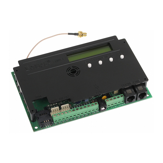
GSM-4S SATEL Figure 1. Hookup of the module to telephone line. IMITATIONS OF USE As the mobile phones are designed for the maximum efficiency of speech conveyance, the data compression feature which is used in them brings about distortions in the transmitted audio signals, which may make difficult or even impossible sending modem signals through a simulated telephone line (downloading, monitoring). - Page 6 The OT3 output can play the role of a telephone line trouble indicator – settings option. The figure 2 shows the arrangement of terminals and essential elements, which are important for connecting and programming the GSM-4S module. EXTERNAL ANTENNA CONNECTOR SIM300C telephone...
- Page 7 GSM-4S SATEL The module has the built in LCD display which is used for reading the information on the current status of the module, and for programming the data required during normal operation. In the first line of LCD display (during normal operation), the following information is displayed: the telephone line status, the SIM300CZ telephone status, power level of the signal received by antenna (0–4) and the status of the inputs and the outputs of the module.
- Page 8 – GSM telephone symbol GSM telephone status symbol displayed during – incoming call to GSM modem connection telephone RS-232 port – receiving data telephone line status – sending data antenna signal level – telephone set symbol – telephone receiver has status of inputs/outputs been picked up (see table 1)
-
Page 9: Operating The Sim300Cz Telephone
5. I NSTALLATION It should be remembered during installation that the GSM-4S module must not be located in the vicinity of electrical installations, since this may involve a risk of malfunctioning. Pay special attention to how the cable is laid between the module and the telephone jack of the alarm control panel. - Page 10 − SIM300CZ telephone trouble The module power supply should have sufficient current capacity. The recommended power supply (for example, the SATEL manufactured APS-15 or APS-30) should be equipped with its own battery. It is suggested that the power supply be located within 3 m from the module.
-
Page 11: Operation Of The Module With Alarm Control Panel And Stationary Telephone
It is possible to disable the function of automatic switchover of the cable telephone line to GSM by deselecting the Trouble – switch line option. The telephone line simulation mode, in which the GSM-4S module takes over the task of handling the devices connected to the T-1 and R-1 terminals, consists in providing across these terminals impedance and voltage required for proper operation of the telephone. -
Page 12: Gsm-4S With Monitoring Station
The STAM-1 monitoring station (from version 4.07) only supports SMS monitoring related to the input status of the GSM module located on the site (e.g. GSM-4S or GSM LT-2S). Changing the status of the device inputs will result in sending the event as a preprogrammed contents SMS message to the GSM module number on the monitoring station side. -
Page 13: Description Of Outputs And Inputs Of The Module
8.1 O UTPUTS The GSM-4S has 3 outputs (type OC, current carrying capacity 50 mA), which can be used to control operation of electrical devices. The status of outputs can be controlled locally (manually), with the use of module buttons, or remotely –... - Page 14 User Manual GSM-4S such change as violation of the input. This time delay can have the values within the range from 20 ms to 1275 ms. The time to restore the input is the next parameter to be programmed for each input. Time...
-
Page 15: Methods Of Controlling The Status Of The Outputs And Bypassing The Inputs
ETHODS OF CONTROLLING THE STATUS OF THE OUTPUTS AND BYPASSING THE INPUTS Changing the state of outputs and bypassing the inputs of the GSM-4S module can be effected remotely (by tone from telephone keypad, by SMS message, through CLIP), locally (using the module keys, by tone from terminals T-1, R-1), and also by violating the selected input. -
Page 16: Remote Bypassing By Sms Messages
(functions: SMS acknowl. No., SMS centre No.), then after executing the control of individual output by SMS message, the GSM-4S module sends the message confirming the type of control and the present status of outputs. -
Page 17: Controlling Outputs By Means Of Clip Function
GSM-4S SATEL forward an SMS to a different number than that programmed in the module, it is necessary to insert this number after the control message in the following way: "xxxx=yyyy.", where "xxxx" denotes the control code, and "yyyy" – the telephone number to which the message is to be sent by the module. -
Page 18: Local Control
– switching OFF all outputs; bypassing IN4 The manual bypassing/unbypassing the inputs is also implemented by the GSM-4S module’s push-buttons. Pressing one of these push-buttons three time will cause bypassing the input of the number corresponding to the number of a given push-button (see: description of module’s push-button). -
Page 19: Controlling Inputs And Outputs By The Violation Of Inputs
GSM-4S SATEL In order to bypass/unbypass the input or enable/disable the output from terminals R-1, T-1, do the following: • Pick up the receiver and enter the control code (if correct, the device will generate four short beeps and a long one). -
Page 20: Sms Messages
User Manual GSM-4S 10.1 SMS MESSAGES The SMS messages to be transmitted can have standard contents or can be modified by the user. The user's own message can be entered by using the module’s push-buttons or by utilizing the SMS message sent from another telephone to the SIM300CZ telephone number. -
Page 21: Clip
The transmission acknowledgement consists in the telephone user rejecting or receiving the connection set up by the GSM-4S module. The acknowledgement may only come within 10 to 20 seconds of the connection set-up. In addition, the number of attempts (1–15) to transmit the information can be programmed individually for each telephone number. -
Page 22: Transmitting Sms Messages
The telephone number, as programmed in the control panel, must consist of: 1. The "pager station number" preprogrammed in the GSM-4S module (Pager tel. No. service function). -
Page 23: Description Of The Procedure For Converting Pager Message Into Sms Message
ENDING MESSAGES FROM A STATIONARY TELEPHONE SET The GSM-4S module user has an option to send SMS messages form a stationary telephone set which generates DTMF signals and is connected to the terminals R-1 and T-1. In order to send an SMS you should: 1. -
Page 24: The Rules For Converting The Numbers
Pressing the [#] key when the module is in the numeric mode results in ending the programming and sending the message. The GSM-4S module can store in its memory 62 alphanumeric characters to be sent as an SMS message. At an attempt to enter a longer message, the excessive portion of the text will be omitted. -
Page 25: Monitoring Gsm-4S Module Status
(TIP, RING) or through the RS-232 port 12.2.1 Connection through TIP, RING terminals When connected to the control panel telephone output, the GSM-4S module will simulate the telephone monitoring station, i.e. the control panel will dial the monitoring station telephone... -
Page 26: Dload10 Program
GSM-4S 13. DLOAD10 PROGRAM The GSM-4S module delivery set includes the DLOAD10 program, which enables the module to be programmed from a computer. The program is designed for IBM PC/AT compatible computers. It works in any computer hardware configuration in the WINDOWS (9x/ME/2000/XP) environment. It is recommended that the program be installed on the computer hard drive. - Page 27 GSM-4S SATEL Figure 9. 7. Save new data in the module by clicking on the icon. 8. If necessary, you can save the programmed data as a file on the computer disk. 9. Disconnect the cable used for programming. Note: Never carry out functional test of the module with cable connected to RS port.
-
Page 28: Gsm-4S" Tab
User Manual GSM-4S 13.1 “GSM-4S” T Figure 11. This tab allows the user to configure the basic working parameters of the module. The parameters programmable in the GSM-4 tab correspond to the control functions and have been reviewed in section Description of service functions (p. 36). -
Page 29: Telephone Messaging " Tab
GSM-4S SATEL 13.2 “T ” ELEPHONE MESSAGING Figure 12. The tab enables messaging parameters to be configured. The parameters programmable in the Telephone messaging tab correspond to the control functions and have been reviewed in section Description of service functions (page 36). -
Page 30: Control /Inputs /Outputs " Tab
User Manual GSM-4S 13.3 “C ” ONTROL NPUTS UTPUTS Figure 13. The parameters programmable in the Control/Inputs/Outputs tab correspond to the control functions and have been reviewed in section Description of service functions (page 36). -
Page 31: Gprs/Monitoring " Tab
GSM-4S SATEL 13.4 "GPRS/M " ONITORING Figure 14. Shown in Figure 14 is a view of the GPRS/Monitoring tab. The presented values are just example settings. By default, the GPRS transmission data are not programmed. All the options are discussed in detail in section Description of service functions (page 36). -
Page 32: Service Mode
User Manual GSM-4S The generator enables CID code to be quickly defined for the following event: – Group – type of the event, – Event – code and description of the event, – Partition – the partition number to be sent, –... - Page 33 GSM-4S SATEL Service mode menu: End of service Service code Line loss time GSM loss time Time of ringing Turn off TL volt Show T l.failure Show dialing. Signal testing CLIP -> number Any numbers Routing signal GSM main line Trbl.
- Page 34 User Manual GSM-4S SMS IN1 violat. SMS IN2 violat. SMS IN3 violat. SMS IN4 violat. SMS fail. line SMS IN1 restor. SMS IN2 restor. SMS IN3 restor. SMS IN4 restor. SMS restor.line SMS test SMS tst.w.state TL ok, mess.IN1 TL ok, mess.IN2 TL ok, mess.IN3...
- Page 35 GSM-4S SATEL SMS OT123 on SMS check I/O SMS "service" SMS "user" SMS mod. format SMS test period SMS change tel1 SMS change tel2 SMS change tel3 SMS change tel4 DTMF control DTMF bypass IN1 DTMF bypass IN2 DTMF bypass IN3...
- Page 36 User Manual GSM-4S Input IN2 restore Input IN3 restore Input IN4 restore IN1 bypass after IN2 bypass after IN3 bypass after IN4 bypass after IN1 autoreset IN2 autoreset IN3 autoreset IN4 autoreset IN1 bypass dur. IN2 bypass dur. IN3 bypass dur.
- Page 37 GSM-4S SATEL Station 1 key Module 1 key St.1 sys. ID Station 2 addr. Station 2 port Station 2 key Module 2 key St.2 sys. ID Station1 tel. n. Station 2 tel. n. Acknow.durat. Tel.event->SMS Skip SMS Skip audio St.1 SMS tel.n.
-
Page 38: Description Of Functions For Programming The Module
User Manual GSM-4S 15. D ESCRIPTION OF FUNCTIONS FOR PROGRAMMING THE MODULE It is required for the functions for programming the module operation to set option, select items from the list, or possibly enter numeric or alphanumeric data (telephone numbers, SMS messages). - Page 39 T-1, R-1 terminals. If this option is selected and after picking up the receiver we press the FLASH key, then GSM-4S module switches from basic telephone line to alternative. Which line is the basic one (cable network or wireless GSM network) is determined with GSM main line function.
- Page 40 User Manual GSM-4S Allowed numbers – the move to submenu for programming the telephone numbers accepted by the module. Tel. No. 1–32 beginning – for these functions it is required to enter the first digits (any number of digits), or complete telephone numbers, to which the calls can be made via SIM300CZ telephone –...
- Page 41 CLIP -> Tel. – type of answer (SMS/CLIP/AUDIO) to the user's CLIP to confirm availability of the device. The programming procedure is identical as for violation of inputs. Note: The telephone to which the GSM-4S module is to call back (CLIP and voice message) must be on the list of permitted numbers.
- Page 42 User Manual GSM-4S the DLOADX/DLOAD64 program, send to the module the following SMS message: "password=yyyy.", where the "yyyy" means the telephone number to be called back by the control panel. Put a dot after the telephone number. If the sent message contains no telephone number, the panel will connect to the number preprogrammed in its memory.
- Page 43 GSM-4S SATEL DTMF off OT123 – DTMF code permitting the system to switch OFF all outputs simultaneously. DTMF on OT123 – DTMF code allowing the system to switch ON all outputs simultaneously. DTMF check outs – DTMF code allowing the system to check the state of all outputs. The way of signaling is described in section Remote controlling by dtmf signals from touch –...
- Page 44 It is possible to read out the loaded PIN code after calling this function. If necessary, the code is transmitted from the GSM-4S module to the telephone. Entering the wrong PIN code can result in blocking SIM card. In case of such situation, the message is displayed on the module’s display with a request for entering the...
- Page 45 Inter. SMS cent. – the option indicates whether the programmed number of SMS centre is a full international number. SMS acknowl. No. – mobile telephone number to which the GSM-4S module will send the SMS message, confirming execution of the control (through SMS) and containing the current state of inputs and outputs.
- Page 46 User Manual GSM-4S Using the digit 0 in the identifier is not recommended. Default value: 0000 (this sequence means that there is no identifier). Station 1 tel. n./Station 2 tel. n. – telephone numbers of monitoring stations to which event messages will be sent (up to 16 digits).
- Page 47 RS port, and stops the operation when the computer DTR signal disappears. Modem format – setting parameters of the modem the GSM-4S module communicates to. The table below shows all the available modem formats and the codes assigned to them,...
-
Page 48: Examples Of Programming The Numbers And Prefixes
User Manual GSM-4S MCC (Mobile Country Code) – country code MNC (Mobile Network Code) – operator code BSIC (Base Station Identity Code) – base station code CELLID (Cell Identity) – cell identifier RLA (receive level acces minimum) (transmit power maximum CCCH) Erase settings - erasing all telephone numbers and prefixes and restoring default settings for options and times. - Page 49 GSM-4S SATEL − Any number: option OFF − Signal testing: option chosen − Permanent prefix: "602", "501", "39" − Prefix to erase: "0" − Prefix to add: "58" − Telephone numbers: "581110011", "582220022", "583330033", "602440440", "501550550", 39778899" The remaining prefixes and numbers should be blank.
-
Page 50: Technical Data
(FS-87 to FS-90 in the control panel CA-6; FS-87 to FS-94 in the control panel CA-10): 1111602123123 The parameters of the paging system to be programmed in the alarm control panel should have the following form (FS-118 in the SATEL control panel CA-6 and CA-10): 1C 22 0A 0E 70 8A Note: The cellular network operator may require that the "+"... - Page 51 SATEL sp. z o.o. ul. Schuberta 79 80-172 Gdańsk POLAND tel. + 48 58 320 94 00 info@satel.pl www.satel.pl...