
Subscribe to Our Youtube Channel
Related Manuals for Satel INT-GSM


Summary of Contents for Satel INT-GSM
- Page 1 INT-GSM GPRS communication module Firmware version 1.00 int-gsm_en 07/18 SATEL sp. z o.o. • ul. Budowlanych 66 • 80-298 Gdańsk • POLAND tel. +48 58 320 94 00 www.satel.eu...
- Page 2 The name plate of the device is located on the enclosure base. FreeRTOS is used in this device (www.freertos.org). SATEL's goal is to continually upgrade the quality of its products, which may result in some changes of their technical specifications and firmware. The current information on the introduced modifications is available on our website.
-
Page 3: Table Of Contents
6.1.2 Initiating connection by SMS message .....................35 6.1.3 Initiating connection from the keypad (by the control panel) ............35 6.1.4 Establishing connection via the SATEL server .................36 INTEGRA CONTROL application ................... 36 6.2.1 Configuring the settings in INTEGRA CONTROL application (Android) ..........36 6.2.2 Configuring the settings in INTEGRA CONTROL application (iOS) ..........38... -
Page 4: Introduction
SATEL 1. Introduction This manual describes the INT-GSM module and how it should be installed and configured. The module is supported by the INTEGRA / INTEGRA Plus alarm control panels with firmware version 1.18 or newer. The module can be connected directly to the control panel or to the ETHM-1 Plus module (firmware version 2.05 or newer required) which is connected to... - Page 5 Dual Path Reporting compliant with EN 50136. Electronics board RS-485 port to enable connection of INT-GSM module to ETHM-1 Plus module. Communication bus for connection of INT-GSM module to keypad bus of the alarm control panel. RS-232 port to allow: ...
- Page 6 INT-GSM SATEL Fig. 1. Module connected to the INTEGRA / INTEGRA Plus alarm control panel. Fig. 2. Module connected to the ETHM-1 Plus Ethernet module.
-
Page 7: Description Of The Module
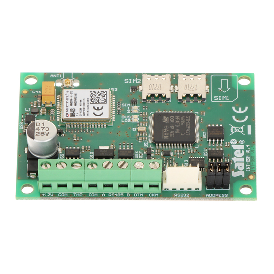
INT-GSM 3. Description of the module Electronics board Fig. 3. INT-GSM module electronics board. antenna cable (the antenna is delivered with the module). slot in which the second SIM card is to be installed. slot in which the first SIM card is to be installed. -
Page 8: Installation
Setting the address is required if the module will be connected to the keypad bus of the alarm control panel. If the INT-GSM module will be connected to the ETHM-1 Plus module, you do not have to set the address. -
Page 9: Installation Of Antenna
(the control panel does not support devices with the same address). Installation of antenna The INT-GSM module is delivered with an antenna. The antenna can be replaced with another antenna mounted on the enclosure or at some distance from it. If this is the case, you will need the IPX-SMA adapter. -
Page 10: Connecting To The Ethm-1 Plus Module
INT-GSM SATEL Fig. 5. Wiring diagram of the cable connecting RS-232 ports of INT-GSM module and INTEGRA / INTEGRA Plus control panel with RJ type connector socket. Fig. 6. Wiring diagram of the cable connecting RS-232 ports of INT-GSM module and INTEGRA control panel with PIN5 connector socket. -
Page 11: Starting The Module
2. Start the identification function in the control panel (see the control panel installer manual). If the module is connected to the alarm control panel, it will be identified as “INT-GSM”. If the module is connected to the ETHM-1 Plus module, “ETHM+-GSM” (instead of “ETHM-1”) will appear on the list of devices. -
Page 12: Int-Gsm
INT-GSM This section describes settings of the INT-GSM module connected directly to the alarm control panel. Description of the settings of the INT-GSM module connected to the ETHM-1 Plus module you will find in the ETHM-1 Plus module manual. Fig. 9. DLOADX program: settings of the INT-GSM module connected directly to the INTEGRA / INTEGRA Plus control panel. - Page 13 INTEGRA CONTROL [Connect GSM] – if this option is enabled, connection can be established between the INTEGRA CONTROL application and the alarm control panel via the module. The connection is set up by the SATEL server. The option is not available when the “INTEGRUM (client)” option is enabled.
-
Page 14: Int-Gsm Functions
SATEL server. You can read the QR code by using a mobile device or export to the file and transmit to the users. The QR code facilitates configuring the INTEGRA CONTROL application settings. - Page 15 SATEL INT-GSM Password – password for Internet GPRS connection. DNS server – IP address of DNS server to be used by the module. If the address has been saved by the operator to the SIM card memory, you do not have to program it. Otherwise, it is recommended that you program the IP address of the DNS server.
- Page 16 SMTP server via the INT-GSM module (GPRS). Do not report LAN trouble if INT-GSM connected to NTP server – the option is available if the INT-GSM module is connected to the ETHM-1 Plus module. If this option is enabled, loss of the Ethernet network will not be reported, when connection has been successfully established with the NTP server via the INT-GSM module (GPRS).
-
Page 17: Pre-Paid Support
SATEL INT-GSM ETHM-1 Plus module to which the INT-GSM module is connected (Ethernet). If connection cannot be established over Ethernet, an attempt will be made to establish communication via GPRS. You can enter up to 16 alphanumeric characters (digits, letters and special characters). -
Page 18: Sms Messaging / Clip Control
INT-GSM SATEL where the SIM card account balance is checked automatically, information on the account balance will be sent as an SMS message to the telephones for SMS messaging / CLIP control, for which the “SMS>>” option is enabled (see „SMS messaging / CLIP control”... -
Page 19: Sms Control
SATEL INT-GSM Fig. 12. DLOADX program: “SMS messaging / CLIP control” tab. CLIP control CLIP means calling without establishing connection (you must hang up on hearing the ring signal), i.e. toll-free. The module will identify the phone number of the calling party and respond accordingly. - Page 20 INT-GSM SATEL Fig. 13. DLOADX program: “SMS control” tab. Control SMS – the control command which, if sent in the SMS message, will run in the control panel the function selected in the “Function” field. You can enter up to 16 alphanumeric characters (digits, letters and special characters).
-
Page 21: Reporting
GPRS, SMS messages (no acknowledgement of event code receipt). Using the INT-GSM module in conjunction with the ETHM-1 Plus module makes it possible to implement the Dual Path Reporting in accordance with EN 50136. For information about how to configure the dual path reporting, please refer to the control panel programming manuals. -
Page 22: Remote Firmware Update
INT-GSM SATEL If the INT-GSM module is connected to the ETHM-1 Plus module, priority must also be specified for the Ethernet transmission (ETHM). In the case of SMS reporting, the module gets no acknowledgement of receiving the event codes by the monitoring station, hence this transmission path should be used as the last one. - Page 23 During update of its firmware, the module does not perform its normal functions. Before updating the module firmware, enter the “Service mode” in the alarm control panel. Otherwise, starting the update will make the control panel report that the INT-GSM module is not available.
-
Page 24: User Functions Definition
INT-GSM SATEL SMS initiating update – the control command which, if sent in the SMS message, will start the firmware update. You can enter up to 8 alphanumeric characters (digits, letters and special characters). The command content must be different from that of the other control commands preprogrammed in the control panel. -
Page 25: Macro Commands
SATEL INT-GSM LCD keypad: S S H LCD S ERVICE MODE TRUCTURE ARDWARE KEYPADS ETTINGS GUARDX . n [n = module address]. ADDR For description of the keypad parameters and options, please refer to the programming manual for INTEGRA / INTEGRA Plus control panel (only some of these parameters and options are available for the virtual keypad). -
Page 26: Groups
This method allows you to use macro commands defined for the e.g. INT-TSG keypad in the INTEGRA CONTROL application. Instead of a file with macro commands defined for the INT-GSM module, you can load a file with macro commands defined for the keypad. -
Page 27: Definitions
SATEL INT-GSM Fig. 18. DLOADX program: “Groups” tab. 5.5.2 Definitions You can create and configure macro commands in the “Definitions” tab. The macro command is a sequence of actions, composed of single commands, which are to be done by the control panel when running the macro command. - Page 28 INT-GSM SATEL No confirmation messages – if this option is enabled, no messages will appear to inform you about execution of a command or an error after running a macro command (the screen from which the macro command was run will still be displayed).
- Page 29 SATEL INT-GSM Commands Commands list – commands assigned to the currently highlighted macro command. The buttons allow you to change the order of commands (moving the selected command up and down). Add – click to add to the list a new command, selected in the “Command” field.
-
Page 30: Defining The Macro Commands
INT-GSM SATEL Value – value to be set (if the type of data provides for sending a sequence of characters, you can enter up to 13 characters). Exit delay clearing (no additional parameters to configure). Quick arm – select the arming mode which is to be activated. - Page 31 SATEL INT-GSM 4. Enter a name for the new macro command. 5. If running a macro command is to be each time preceded by user authorization, enable the “Authorization required” option. 6. If the macro command is to be unavailable when any of the partitions managed by the application is armed, enable the “Disabl.
- Page 32 INT-GSM SATEL 9. Click the button and select the icon for the macro command. 10. If the icon is to change depending on the selected output state: enable the “State follow output” option, indicate the output number, select the icons.
- Page 33 SATEL INT-GSM 13. Configure the command parameters. 14. Click the “Add” button. A new command will appear on the list of commands assigned to the macro command. You can still modify parameters of the command after clicking on it (having made the changes, click the “Change” button).
- Page 34 INT-GSM SATEL 18. Enter the group name, if it is to be displayed. 19. Click the button and select the icon for the macro command group. 20. Click the “Add macro” button. A list of all defined macro commands will be displayed.
-
Page 35: Remote Programming / Operating Of Control Panel Via Module
GUARDX program If the INT-GSM module is connected to the ETHM-1 Plus module, communication via the INT-GSM module (via GPRS) will only be used if connection via Ethernet cannot be established (see the ETHM-1 Plus module manual). Connection between the GUARDX program and the control panel via the INT-GSM module can be established using one of the following ways: 1. - Page 36 INT-GSM IMEI – individual ID number of the GSM telephone of module. INT-GSM ID – individual ID number assigned to the INT-GSM module by the SATEL server. GUARDX key – a string of up to 12 alphanumeric characters (digits, letters and special characters), used for data encryption during communication between the control panel and the computer with GUARDX program.
-
Page 37: Initiating Connection By Sms Message
“TCP/IP: GUARDX<-ETHM/INT-GSM” and then click the “Start” button. This will display a window with information that the program is waiting for connection. 2. Send to the INT-GSM module the following SMS message: xxxx= (“xxxx” – the control command to initiate establishment of communication with GUARDX program) –... -
Page 38: Establishing Connection Via The Satel Server
INTEGRA CONTROL application is installed. The application can be downloaded from the internet store “Google play” (Android system devices) or “App Store” (iOS system devices). On the www.satel.eu website, you will find links to the locations from which the applications can be downloaded. - Page 39 1. Tap on the screen in the “Communication way” area to select “Connection via SATEL server using IMEI number” as the way of communication. 2. Enter the IMEI number of GSM module telephone. 3. Enter the ID number of INT-GSM module (assigned to the module by the SATEL server).
-
Page 40: Configuring The Settings In Integra Control Application (Ios)
3. Enter the name for alarm system. The name helps to identify the system when the application is in use (you can define settings for multiple alarm systems). 4. Configure settings for communication with the INT-GSM module. The settings can be configured automatically (see “Automatic configuration – QR code” p. 39) or you can enter them manually (see “Manual configuration”... - Page 41 SATEL INT-GSM If the macro commands are not to be imported or are to be imported from file, tap on the screen in the “Import macros” area and change the settings. 7. Tap on “Save” to save the settings. Fig. 26. INTEGRA CONTROL app (iOS system): “New” screen before entering data.
-
Page 42: Establishing The Communication
1. Enable the “Server Satel” option so that the app can connect via SATEL server. 2. Enter the IMEI number of the INT-GSM module GSM telephone.. 3. Enter the ID number of the INT-GSM module (assigned to the module by the SATEL server). -
Page 43: Specifications
SATEL INT-GSM Fig. 28. INTEGRA CONTROL application (Android system): virtual keypad. 7. Specifications Supply voltage ....................12 V DC ±15% Standby current consumption ..................130 mA Maximum current consumption..................250 mA Environmental class according to EN50130-5 ................. II Operating temperature range...................-10...+55°C Maximum humidity ......................93±3% Electronics board dimensions .................
Need help?
Do you have a question about the INT-GSM and is the answer not in the manual?
Questions and answers