Table of Contents
Advertisement
Quick Links
Advertisement
Table of Contents

Related Manuals for Satel GSM LT-1S


Summary of Contents for Satel GSM LT-1S
- Page 1 ® COMMUNICATION MODULE GSM LT-1S USER MANUAL 1.09 12/06 Program version gsmLT1_e...
- Page 2 (+48 58) 320-94-00 fax. (+48 58) 320-94-01 Product description: The GSM LT-1S communication module, designed to interact with the SIM300C mobile phone, makes simulation of the analog telephone line possible by using the cellular communication, and thus enabling telephone messaging about emergency situation in the facility, if the analog line is not available.
-
Page 3: Table Of Contents
CONTENTS 1. GSM LT-1S ................... 2 MODULE FEATURES 2. L ......................3 IMITATIONS OF USE 3. D ....................3 ESCRIPTION OF THE MODULE 4. O SIM300C ................. 5 PERATING THE TELEPHONE 5. I ........................5 NSTALLATION 6. O ..6 PERATION OF THE MODULE WITH ALARM CONTROL PANEL AND STATIONARY TELEPHONE 7. -
Page 4: Gsm Lt-1S Module Features
User Manual GSM LT-1 1. GSM LT-1S MODULE FEATURES • Simulation of analog telephone line by the use of cellular connection. • Interaction with alarm control panels and other equipment (e. g. DT-1 telephone dialer) which use the analog telephone line for transmitting voice information about alarms, or for sending text messages to paging system). -
Page 5: Limitations Of Use
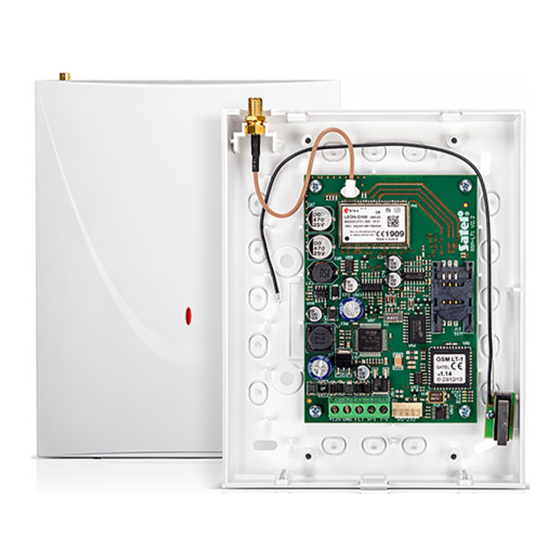
GSM LT-1 SATEL Figure 1. Hooking up the module to telephone line. 2. L IMITATIONS OF USE As the cellular telephones are designed for the best possible transmission of voice signals, it is permissible that their data compression systems cause distortions of the transmitted audio signals. - Page 6 STAT +12V GND FLT R-1 T-1 RS-232 Figure 2. View of the GSM LT-1S module board. LEDs: The module indicates its status to the user by means of 4 LED indicators. The mode of lighting of the STAT and SIG LEDs depends on the module status and provides the information described below.
-
Page 7: Operating The Sim300C Telephone
5. I NSTALLATION It should be borne in mind during installation that the GSM LT-1S module must not be located in the vicinity of electrical installations, since this may involve a risk of malfunctioning. Pay special attention to how the cable is laid between the module and the telephone terminals of the alarm control panel. -
Page 8: Operation Of The Module With Alarm Control Panel And Stationary Telephone
Figure 4. Entering the SIM card into its socket. The module power supply should have a sufficient current capacity. The recommended power supply unit (e.g. APS-15; APS-30 manufactured by SATEL) should be equipped with its own battery. It is suggested that the power supply be located within 3m from the module. -
Page 9: Gsm Lt-1S With Monitoring Station
7. GSM LT-1S WITH MONITORING STATION Figure 5. The GSM LT-1S module permits site monitoring by means of SMS short text messages. This function is offered by the STAM-1 monitoring station program, version 4.07 and STAM-2,... -
Page 10: Sending Sms Messages
SMS messages to the cellular telephone number. The message then sent by the control panel is transferred to the GSM LT-1S module, not to the pager station. For example: the alarm control panel CA-64 or INTEGRA can send messages to three different paging systems. -
Page 11: Sending Sms Messages From A Stationary Telephone Set
[#] key when the module is in the numeric mode results in ending the programming and sending the message. The GSM LT-1S can store in its memory 62 alphanumeric characters to be sent as an SMS message. At an attempt to enter a longer message, the excessive portion of the text will be omitted. -
Page 12: Clip" Test Transmission
The CLIP type information makes use of the calling number presentation function and may be used to confirm that the GSM LT-1S module is in good working order. This type of messaging consists in dialing a programmed telephone number by the SIM300C telephone and then breaking the connection after approx. -
Page 13: Sms Control
DTMF signals, as well as enables the module status and antenna signal level to be checked. In order to change the settings or check the status you should first enter the GSM LT-1S module programming mode. This operation requires entering a six-digit access code. By default, this code is 123456 and can be changed. -
Page 14: Function List
User Manual GSM LT-1 Programming the module settings In order to call the programming function, select the function number (two digits), press the [ * ][ * ] asterisk key twice, enter the parameter suitable for the given function and press the [#] key. - Page 15 GSM LT-1 SATEL telephone” in order to start the downloading function. If the control panel is to call back to another number, the number should into content follows: [?][?][?][?][?][?]=dddd. (password, equality sign, telephone number, point). Using DTMF signals it is possible to program a password comprised of digits only (0...9), while using the...
- Page 16 User Manual GSM LT-1 format code modem format auto 300 V.21 1200 V.22 1200/75 V.23 2400 V.22bis 2400 V.26ter 4800 V.32 9600 V.32 9600 V.34 14400 V.34 300 V.110 1200 V.110/X.31 2400 V.110/X.31 4800 V.110/X.31 9600 V.110/X.31 14400 V.110/X.31 [0]9][ * ][ * ][?][#] - RS-232 port speed.
- Page 17 GSM LT-1 SATEL antenna signal. The signaling is same as that of the SIG LED. The following answer beeps are possible: two long (LL) – antenna signal strength = 0 one short (S) – antenna signal strength = 1 two short (SS) – antenna signal strength = 2 three short (SSS) –...
- Page 18 User Manual GSM LT-1 1 – test transmission 2h58min, 2 – test transmission 5h57min, 3 – test transmission period 11h56min, 4 – test transmission period 23h55min, 5 – test transmission period 2d23h53min, 6 – test transmission period 6d23h30min. [2][0][ * ][ * ][?][#] - test transmission priority.
- Page 19 GSM LT-1 SATEL an SMS with the [?][?][?][?][?][?]=P sequence, where P is a parameter corresponding to the description contained in function 19, will save the new parameter, programmed with function 19, in the module memory. Using the DTMF signals, you can program passwords composed from digits only (0...9), whereas the Dload10 program makes it possible to program passwords composed from letters and digits.
- Page 20 User Manual GSM LT-1 transmission, will change the parameter programmed with function 24. The new telephone number must be identical in form to that programmed with the appropriate function. Using the DTMF signals, you can program passwords composed from digits only (0...9), whereas the Dload10 program makes it possible to program passwords composed from letters and digits.
-
Page 21: Dload10 Program
SATEL 11. DLOAD10 PROGRAM The GSM LT-1S module is delivered together with the DLOAD10 program which enables the module to be programmed from a computer. The program is designed for IBM PC/AT compatible computers. It works in any computer hardware configuration in the WINDOWS (9x/ME/2000/XP) environment. It is recommended that the program be installed on the computer hard disk. - Page 22 User Manual GSM LT-1 Figure 8. 2. Enter the options of module communication settings by clicking on the icon (or through the Communication Configuration menu) and select the port through which the computer connects with the module RS-232 port (see figure 9). Figure 9.
-
Page 23: Technical Data
Required minimum output current, power supply unit .............500mA Current-carrying capacity, FLT output ................50mA ATTENTION: The SATEL Company recommends that performance of the GSM LT-1S communication module be regularly tested. An efficient GSM module, which interacts with the security system, greatly increases the chance of successful transmission of alarm information. -
Page 24: History Of The Manual Updates
Introduced description of new functions 26-40 (p. 18). Updated Figure 10 (p. 21). IMPORTANT: PIN......... PUK ................Telephone No..................................................................................................SATEL sp. z o.o. ul. Schuberta 79 80-172 Gdańsk POLAND tel. + 48 58 320 94 00 info@satel.pl www.satel.pl...
Need help?
Do you have a question about the GSM LT-1S and is the answer not in the manual?
Questions and answers