Table of Contents
Advertisement
Quick Links
Download this manual
See also:
User Manual
Advertisement
Table of Contents

Related Manuals for Satel GSM-4S


Summary of Contents for Satel GSM-4S
- Page 1 ® COMMUNICATION MODULE GSM-4S USER MANUAL Program version 4.09 gsm4_e 01/07...
- Page 2 (+48 58) 320-94-00 fax. (+48 58) 320-94-01 Product description: The GSM-4S communication module, designed to interact with the SIM300C mobile phone, allowing simulation of the analog telephone line by making use of the cellular connection and thus making possible to report alarm conditions in the facility if the analog line is damaged or non- existent.
-
Page 3: Table Of Contents
CONTENTS 1. GSM-4 ....................2 MODULE FEATURES 2. L ......................... 3 IMITATIONS 3. D ....................3 ESCRIPTION OF THE MODULE 4. O GM47 ..........7 PERATING INSTRUCTION FOR THE CELLULAR TELEPHONE 5. I ........................7 NSTALLATION 6. O ... 9 PERATION OF THE MODULE WITH ALARM CONTROL PANEL AND STATIONARY TELEPHONE 7. -
Page 4: Gsm-4 Module Features
User Manual GSM-4S 1. GSM-4S MODULE FEATURES • Simulation of analog telephone line by the use of cellular connection - which makes it possible to report an alarm situation at the site in case the analog line is out of order or missing. -
Page 5: Limitations
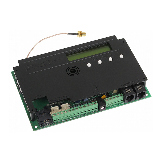
GSM-4 SATEL Figure 1. Hookup of the module to telephone line. IMITATIONS Since cellular telephones are designed having in view the best possible transmission of the voice signals, it is reasonable that the data compression systems, which are used in cellular communication, introduce distortions into the audio signals transmitted. - Page 6 SUPPLY SOCKET JACKS Figure 2. View of PCB of GSM-4S module. For power supply of external equipment you should use the +V & –V outputs, whose max. current load must not exceed 300mA. It should be borne in mind, that the capacity of connected power supply unit must be adequate for power demand of the module and the devices connected to it.
- Page 7 GSM-4 SATEL The module has the built in LCD display which is used for reading the information on the current status of the module, and for programming the data required during normal operation. In the first line of LCD display (during normal operation), the following information is displayed: the telephone line status, the SIM300C telephone status, power level of the signal received by antenna (0-4) and the status of the inputs and the outputs of the module.
- Page 8 - GSM telephone symbol GSM telephone status symbol displayed during - incoming call to GSM modem connection telephone RS-232 port - receiving data telephone line status - sending data antenna signal level - telephone set symbol telephone receiver has status of inputs/outputs been picked up (see table 1) connection type...
-
Page 9: Operating Instruction For The Ogm47 Cellular Telephone
5. I NSTALLATION It should be remembered during installation that the GSM-4S module must not be located in the vicinity of electrical installations, since this may involve a risk of malfunctioning. Pay special attention to how the cable is laid between the module and the telephone jack of the alarm control panel. - Page 10 − SIM300C telephone trouble The module power supply should have sufficient current capacity. The recommended power supply (for example, the SATEL manufactured APS-15 or APS-30) should be equipped with its own battery. It is recommended that the power supply unit be situated within 3m distance from the module.
-
Page 11: Operation Of The Module With Alarm Control Panel And Stationary Telephone
(if this is impossible, the module selects a substitute way). When making a call from the telephone connected to the GSM-4S module, the user has the option to select the connection route: via cable or via GSM. Lifting the handset makes the basic line available for getting connections. -
Page 12: Gsm-4 With Stam-1 Monitoring Station
8. D ESCRIPTION OF OUTPUTS AND INPUTS OF THE MODULE The GSM-4S module is equipped with three outputs and four inputs of the technical features similar to those of inputs and outputs of the alarm control panel. The attendance of the... -
Page 13: Utputs
"1" – output is ON: active status (contact OTn shorted to ground; n= 1,2,3). The GSM-4S module has 3 outputs, which can be used for controlling the electrical equipment. The control of the output’s status can be done remotely by telephone (traditional or cellular), or manually by using the module’s push–buttons. -
Page 14: Nputs
User Manual GSM-4S • simultaneous disabling of all outputs – all outputs will be deactivated, irrespective of their previous status, • simultaneous enabling of all outputs – all outputs will be activated, irrespective of their previous status. The control of outputs is possible upon programming the appropriate service functions (submenu: SMS control, DTMF control). -
Page 15: Description Of Methods Of Controlling The Status Of The Outputs And Bypassing The Inputs
GSM-4S SATEL Figure 8. The ways of remotely controlling the status of outputs and the bypass of inputs of the module. 9. D ESCRIPTION OF METHODS OF CONTROLLING THE STATUS OF THE OUTPUTS AND BYPASSING THE INPUTS 9.1 R DTMF –... -
Page 16: Remote Control By Sms Messages
User Manual GSM-4S Note: When receiving a call, the module applies ringing tone to extension line for the duration equal to "Time of ringing". Answering a call from this extension line makes it impossible to use the functions for controlling the outputs. -
Page 17: Acknowledgement Of Executing The Sms Control
No."), then after executing the control of individual output by SMS message, the GSM-4S module sends the message confirming the type of control and the present status of outputs. The acknowledgement can also be sent to another telephone number. For the module to forward an SMS to a different number than that programmed in the module, it is necessary to insert this number after the control message in the following way: „xxxx=yyyy.",... -
Page 18: Controlling The Outputs By The Violation Of Inputs
User Manual GSM-4S For designation of inputs, character "?" is replaced with the letter: i or t - input in normal status unbypassed (non-violated), I or T - input unbypassed violated, - input bypassed. For the telephone line designation, the "?" character is replaced with the following ones: ok - the telephone line in good working order, ?? - the telephone line out of order. -
Page 19: Manual Control
IN4 9.6.2 Inputs The manual bypassing/unbypassing the inputs is also implemented by the GSM-4S module’s push–buttons. Pressing one of these push–buttons three time will cause bypassing the input of the number corresponding to the number of a given push–button (see: description of module’s push–button). -
Page 20: Sms Messages
User Manual GSM-4S The messages can be sent maximally to four telephone numbers. The messaging can have a form of SMS message, the sound information or CLIP type information. For the voice messaging, it is possible to initiate the function of calling a given number twice (two phone... -
Page 21: Voice Messaging
GSM-4S SATEL • Both push-buttons must be pressed simultaneously, otherwise the module will enter the mode for manual editing the message and it will be necessary to renew the procedure for reading the message from SMS. • The length of the message stored in the module’s memory is limited to 32 characters. -
Page 22: Transmitting Sms Messages
SMS messages to the cellular telephone number. The message transmitted by the control panel is transferred to the GSM-4S module, not to pager station. For example: the alarm control panel CA-64 or INTEGRA can send messages to three different paging systems. -
Page 23: Description Of The Procedure For Converting Pager Message Into Sms Message
ENDING MESSAGES FROM A STATIONARY TELEPHONE SET The GSM-4S module user has an option to send SMS messages form a stationary telephone set which generates DTMF signals and is connected to the terminals R-1 and T-1. This operation is done in much the same way as sending SMS messages in the PAGER system. -
Page 24: The Rules For Converting The Numbers
Pressing the [#] key when the module is in the numeric mode results in ending the programming and sending the message. The GSM-4S module can store in its memory 62 alphanumeric characters to be sent as an SMS message. At an attempt to enter a longer message, the excessive portion of the text will be omitted. -
Page 25: Service Mode
GSM-4S SATEL The algorithm of converting the number is as follows: 1. If the dialed number begins with one of permanent prefixes (prefix -digits added before the exact telephone number), the module skips to step 4. 2. If the dialed number begins with a "prefix to be erased" this prefix is erased and the module skips to step 4. - Page 26 User Manual GSM-4S The module in the service mode operates in the same way, as during normal mode i. e. it is possible to make and answer calls, but the status is not displayed. Instead of the status, the description of service functions are displayed, thus enabling the user to go through the menu of service mode and to make appropriate changes in the module’s configuration.
- Page 27 GSM-4S SATEL Service mode menu: End of service Service code Line loss time GSM loss time Time of ringing Turn off TL volt Show T l.failure Show dialing. Signal testing Answering calls Any numbers Routing signal GSM main line Trbl. – switch l.
- Page 28 User Manual GSM-4S SMS IN1 violat. SMS IN2 violat. SMS IN3 violat. SMS IN4 violat. SMS fail. line SMS IN1 restor. SMS IN2 restor. SMS IN3 restor. SMS IN4 restor. SMS restor.line SMS test SMS tst.w.state TL ok, mess.IN1 TL ok, mess.IN2 TL ok, mess.IN3...
- Page 29 GSM-4S SATEL SMS „user" SMS mod. format SMS test period SMS change tel1 SMS change tel2 SMS change tel3 SMS change tel4 DTMF control DTMF bypass IN1 DTMF bypass IN2 DTMF bypass IN3 DTMF bypass IN4 DTMF bypass all DTMF unbyps.IN1 DTMF unbyps.IN2...
-
Page 30: Description Of Functions For Programming The Module
User Manual GSM-4S IN4 bps.aft.1v. IN1 bps.aft.3v. IN2 bps.aft.3v. IN3 bps.aft.3v. IN4 bps.aft.3v. IN1 bps. manual.. IN2 bps. manual. IN3 bps. manual. IN4 bps. manual. Bypassing input Bypassed inputs OT1 cut-off t. OT2 cut-off t. OT3 cut-off t. OT3 – t.l. trbl. -
Page 31: Entering Numeric Or Alphanumeric Data
GSM-4S SATEL 14.2 E NTERING NUMERIC OR ALPHANUMERIC DATA After getting access to the function (by pressing push-button OK) which requires entering duration, telephone number, password or message, the blinking cursor is displayed on the module’s display to show the field where the data can be entered. Each pressing the push- button CHANGE will result in changing the displayed digit or character. - Page 32 T-1, R-1 terminals. If this option is selected and after picking up the receiver we press the FLASH key, then GSM-4S module switches from basic telephone line to alternative. Which line is the basic one (cable network or wireless GSM network) is determined with „GSM main line"...
- Page 33 GSM-4S SATEL option is set, the above mentioned telephone numbers are of no importance. The numbers to be entered must have the same form as the numbers dialed by the GSM telephone i.e. must contain area code, for instance: "602 123456", "58 5551122". If the initial digits are programmed, the dialed number must contain all these programmed digits at the beginning.
- Page 34 User Manual GSM-4S CHANGE. The successive pressing makes the character display at the telephone numbers: s – SMS message to be sent c – CLIP type message v – sound message to be sent. (no display) – indicates that a given number is omitted while violating a given input.
- Page 35 GSM-4S SATEL SMS check I/O - the function assigning the password allowing the system to check the state of all inputs and outputs. After receiving this password, the module sends the text message on the present state of outputs and inputs, telephone line status, transmission period and telephone numbers to be notified .
- Page 36 User Manual GSM-4S DTMF bypass all - the function assigning the code, which permits the system to bypass all inputs simultaneously. DTMF unbyps. In. 1…4 - the functions assigning the codes enabling the system to unbypass separate input. DTMF unbypas. all - the function assigning the code permitting the system to unbypass all inputs simultaneously.
- Page 37 PIN code after calling this function. If necessary, the code is transmitted from the GSM-4S module to the telephone. Entering the wrong PIN code can result in blocking SIM card. In case of such situation, the message is displayed on the module’s display with a request for entering the PUK code.
- Page 38 RS port, and stops the operation when the computer DTR signal disappears. Modem format – function used for setting parameters of the modem the GSM-4S module communicates to. The table below shows all the available modem formats and the codes assigned to them, which are necessary to change the pre-programmed modem for another one by means of an SMS message.
-
Page 39: Dload10 Program
Immediately after the exit from the function by pressing push-button "OK". 15. DLOAD10 PROGRAM The GSM-4S module delivery set includes the DLOAD10 program, which enables the module to be programmed from a computer. The program is designed for IBM PC/AT compatible computers. It works in any computer hardware configuration in the WINDOWS (9x/ME/2000/XP) environment. - Page 40 User Manual GSM-4S The program installation consists in running the setup.exe program from a floppy disk delivered with the module. After installation, the program should be launched. Access to the program is protected with an access code. After installation of the program, the access code is: 1234 and can be changed in any string of 16 alphanumeric characters.
- Page 41 - see figure 13). By default, the password (AAAAAA) is not preprogrammed in the GSM-4S module. Figure 13. 5. Read out data from the module by clicking on the icon. The communication establishing process is presented by an appropriated message on the GSM-4S task bar. 6. Program the module.
-
Page 42: Examples Of Programming The Numbers And Prefixes
Note: Never carry out functional test of the module with cable connected to RS port. To facilitate using the program and programming the GSM-4S module parameters itself, a HELP system is provided. The system is accessible from the „HELP" menu or, after pressing the F1 key, from the computer keyboard. - Page 43 (FS-87 to FS-90 in the control panel CA-6; FS-87 to FS-94 in the control panel CA-10): 1111602123123 The parameters of the paging system to be programmed in the alarm control panel should have the following form (FS-118 in the SATEL control panel CA-6 and CA-10): 1C 22 0A 0E 70 8A Note: The cellular network operator may require that the „+”...
-
Page 44: Basic Technical Data
(without outputs supply) Required minimum output current of power supply unit ..........500mA ATTENTION: The SATEL Company recommends that performance of the GSM-4S communication module be regularly tested. An efficient GSM module, which interacts with the security system, greatly increases the chance of successful transmission of alarm information. -
Page 45: History Of The Manual Updates
GSM-4S SATEL 18. H ISTORY OF THE MANUAL UPDATES Given below is a description of changes in the manual contents as compared with the v4.07 firmware. FIRMWARE DATE DESCRIPTION OF CHANGES VERSION • The module has been adapted for interaction with GSM SIM300C industrial telephone . - Page 46 SATEL sp. z o.o. ul. Schuberta 79 80-172 Gdańsk POLAND tel. + 48 58 320 94 00 info@satel.pl www.satel.pl...
Need help?
Do you have a question about the GSM-4S and is the answer not in the manual?
Questions and answers