Sign In
Upload
Download
Table of Contents
Contents
Add to my manuals
Delete from my manuals
Share
URL of this page:
HTML Link:
Bookmark this page
Add
Manual will be automatically added to "My Manuals"
Print this page
×
Bookmark added
×
Added to my manuals
Manuals
Brands
Satel Manuals
Control Unit
GSM-4
Manual
Satel GSM-4 Manual
Communication module
Hide thumbs
1
2
Table Of Contents
3
4
5
6
7
8
9
10
11
12
13
14
15
16
17
18
19
20
21
22
23
24
25
26
27
28
29
30
31
32
33
34
35
36
37
38
39
40
41
42
43
44
45
46
47
48
49
50
51
52
53
54
55
56
57
58
59
60
61
62
63
64
page
of
64
Go
/
64
Contents
Table of Contents
Bookmarks
Table of Contents
Table of Contents
1 General
2 Module Features
3 Typical Module Applications
Backup Communication Path
Supervision / Control of Devices
Simulation of Monitoring Station
Integration with Integra Control Panels
Working in Conjunction with Stam-1 / Stam-2 Monitoring Station
Working in Conjunction with Pbx Stations
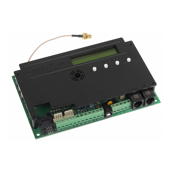
4 Description of the Module
Description of the Electronics Board
Lcd Display
LED Indicators [Only GSM-5]
Buttons
Module Restart
Audible Signaling in the Module
When Controlling Inputs
When Controlling Outputs
In Service Mode
5 Installation
6 Programming
Service Mode
Service Mode Menu
Description of Functions Available Only in Service Mode
Entering Data by Means of Buttons
Load Program
Local Programming
Remote Programming
Main Menu of DLOAD 10 Program
Status Bar
Changing the Program Access Code
GSM-4 / GSM-5" Tab
SIM 1/2" Tab
Control/Inputs/Outputs" Tab
Tel. Messaging" Tab
Reporting" Tab
Reporting - Inputs" Tab
TCP/IP Downloading" Tab
Firmware Update" Tab
Events Buffer" Tab
7 Control
Remote
Tone Control from Telephone Keypad
Using SMS
Using CLIP
Local
Using the Module Buttons
From the Keypad of Telephone Connected to Telephone Line Output
Control from Dload10 Program
8 Starting the Reporting
Starting the Gprs Reporting
Reporting the Module Status (GPRS)
Reporting Events from the Control Panel (GPRS)
Starting the Csd Reporting
Reporting the Module Status (CSD)
Reporting Events from the Control Panel (CSD)
Starting the Sms Reporting
Reporting the Module Status (SMS)
Reporting Events from the Control Panel (SMS)
Starting the Audio Reporting
Starting the Event Reporting over Several Links
9 Starting the Messaging
Starting the Voice Messaging
Starting the Sms Messaging
Changing the Text Messages Content by Means of SMS
Starting the Clip Messaging
10 Converting the Pager Type Messages into Sms Messages
Working in Conjunction with the Dt-1 Dialer
11 Sending Sms Messages from the Telephone Connected to Telephone Line Output
12 The Rules for Converting the Numbers
13 Initiating the Module Firmware Update by Sms Message
14 Restoring the Factory Settings
Dload Program
Service Mode
Module Factory Settings (Dload 10)
15 Specifications
Advertisement
Quick Links
1
General
Download this manual
Communication module
GSM-4/GSM-5
Firmware version 4.14 (GSM-4) / 5.14 (GSM-5)
gsm4_5_en 11/12
SATEL sp. z o.o.
ul. Budowlanych 66
80-298 Gdańsk
POLAND
tel. + 48 58 320 94 00
info@satel.pl
www.satel.eu
Table of
Contents
Previous
Page
Next
Page
1
2
3
4
5
Advertisement
Table of Contents
Need help?
Do you have a question about the GSM-4 and is the answer not in the manual?
Ask a question
Questions and answers
Related Manuals for Satel GSM-4
Control Unit Satel GSM LT-1S User Manual
Communication module (24 pages)
Control Unit Satel GSM LT-1S User Manual
Communication module (24 pages)
Control Unit Satel GSM LT-2 User Manual
Communication module (37 pages)
Control Unit Satel GSM LT-2 Manual
Communication module (51 pages)
Control Unit Satel GSM-4S User Manual
Communication module (46 pages)
Control Unit Satel GSM-4S User Manual
Communication module (51 pages)
Control Unit Satel GSM-X Manual
Communication module (64 pages)
Control Unit Satel GSM-X Quick Installation Manual
Communication module (10 pages)
Control Unit Satel GSM LT-1 Manual
Communication module (38 pages)
Control Unit Satel GSM LT-1 User Manual
Communication module (24 pages)
Control Unit Satel GSM-5 Manual
Communication module (64 pages)
Control Unit Satel GPRS-T6 Manual
Gprs/sms reporting module with power supply (30 pages)
Control Unit Satel GPRS-A Quick Installation Manual
Universal monitoring module (7 pages)
Control Unit Satel GPRS-T4 Manual
Gprs/sms reporting module (28 pages)
Control Unit Satel GSM-X Plus Quick Installation Manual
Communication module (12 pages)
Control Unit Satel ETHM-1 Plus Manual
Ethernet communication module (39 pages)
This manual is also suitable for:
Gsm-5
Table of Contents
Print
Rename the bookmark
Delete bookmark?
Delete from my manuals?
Login
Sign In
OR
Sign in with Facebook
Sign in with Google
Upload manual
Upload from disk
Upload from URL


Need help?
Do you have a question about the GSM-4 and is the answer not in the manual?
Questions and answers