
Related Manuals for Satel GSM LT-1S


Summary of Contents for Satel GSM LT-1S
- Page 1 ® COMMUNICATION MODULE GSM LT-1S USER MANUAL 1.11 gsmLT-1S_en 06/08 Program version...
- Page 2 (+48 58) 320-94-00 fax. (+48 58) 320-94-01 Product description: The GSM LT-1S communication module, designed to interact with the SIM300CZ mobile phone, makes simulation of the analog telephone line possible by using the cellular communication, and thus enabling telephone messaging about emergency situation in the facility, if the analog line is not available.
-
Page 3: Table Of Contents
CONTENTS 1. GSM LT-1S ................... 2 MODULE FEATURES 2. L ......................3 IMITATIONS OF USE 3. D ....................3 ESCRIPTION OF THE MODULE 4. O SIM300CZ ................5 PERATING THE TELEPHONE 5. I ........................5 NSTALLATION 6. O ..6 PERATION OF THE MODULE WITH ALARM CONTROL PANEL AND STATIONARY TELEPHONE 7. -
Page 4: Gsm Lt-1S Module Features
User Manual GSM LT-1S 1. GSM LT-1S MODULE FEATURES • Simulation of analog telephone line by the use of cellular connection. • Interaction with alarm control panels and other equipment (e. g. DT-1 telephone dialer) which use the analog telephone line for transmitting voice information about alarms, or for sending text messages to paging system). -
Page 5: Limitations Of Use
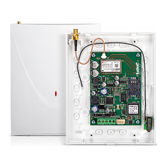
GSM LT-1S SATEL Figure 1. Hooking up the module to telephone line. 2. L IMITATIONS OF USE As the mobile phones are designed for the maximum efficiency of speech conveyance, the data compression feature which is used in them brings about distortions in the transmitted audio signals, which may make difficult or even impossible sending modem signals through a simulated telephone line (downloading, monitoring). - Page 6 +12V GND FLT R-1 T-1 RS-232 Figure 2. View of the GSM LT-1S module board. In its active state, the FLT output is shorted to the ground. The FLT output may be connected to the alarm control panel input, or it can directly control the relay operation (its maximum current-carrying capacity is 50 mA).
-
Page 7: Operating The Sim300Cz Telephone
5. I NSTALLATION It should be borne in mind during installation that the GSM LT-1S module must not be located in the vicinity of electrical installations, since this may involve a risk of malfunctioning. Pay special attention to how the cable is laid between the module and the telephone terminals of the alarm control panel. -
Page 8: Operation Of The Module With Alarm Control Panel And Stationary Telephone
Figure 3. Entering the SIM card into its socket. The module power supply should have a sufficient current capacity. The recommended power supply unit (e.g. APS-15; APS-30 manufactured by SATEL) should be equipped with its own battery. It is suggested that the power supply be located within 3 m from the module. -
Page 9: Gsm Lt-1S With Monitoring Station
SATEL. The example of module connection to station is shown in Fig. 4. Connect the GSM LT-1S module to the computer serial port (COM1 or COM2), by means of the typical cable for programming the GSM module as well as CA-10, CA-64 or INTEGRA control panels (see: Fig. -
Page 10: Sending Sms Messages
ENDING MESSAGES FROM A STATIONARY TELEPHONE SET The GSM LT-1S module user has an option to send SMS messages form a stationary telephone set which generates DTMF signals and is connected to the terminals R-1 and T-1. This operation is done in much the same way as sending SMS messages in the PAGER... -
Page 11: Test Transmission
The GSM LT-1S can store in its memory 62 alphanumeric characters to be sent as an SMS message. At an attempt to enter a longer message, the excessive portion of the text will be omitted. -
Page 12: Test Transmission With Acknowledgement
SMS if there is no acknowledgement of receiving the CLIP information (functions 36–39). The transmission acknowledgement consists in the telephone user rejecting or receiving the connection set up by the GSM LT-1S module. The acknowledgement can only take place within 10 to 20 seconds of the connection set-up. -
Page 13: Module Programming
10.1 DLOAD10 PROGRAM The GSM LT-1S module is delivered together with the DLOAD10 program which enables the module to be programmed from a computer. The program is designed for IBM PC/AT compatible computers. It works in any computer hardware configuration in the WINDOWS (9x/ME/2000/XP) environment. It is recommended that the program be installed on the computer hard disk. - Page 14 User Manual GSM LT-1S Having installed the program, start it. Access to the program is protected with an access code. After installation of the program, the access code is: 1234 and can be changed in any string of 16 alphanumeric characters. As long as the code has its factory setting, pressing the „ENTER”...
- Page 15 GSM LT-1S SATEL Figure 8. Note: Never carry out functional test of the module with cable connected to RS port. Figure 9. Description of parameters indicated in the illustration above: 1 – country code (48 – Poland) 2 – area code to be entered in case of connection to a stationary telephone...
-
Page 16: Programming By Means Of A Telephone Set (Dtmf)
DTMF signals, as well as enables the module status and antenna signal level to be checked. In order to change the settings or check the status you should first enter the GSM LT-1S module programming mode. This operation requires entering a six-digit access code. - Page 17 GSM LT-1S SATEL Entering a correct command is signaled in the handset by three short beeps (SSS), while commands which are incomprehensible or have an incorrect number of characters are signaled by two long beeps (LL). The function completed, the module returns to the programming mode. If you hang up, the module will quit the programming mode and return to the normal operating mode.
- Page 18 User Manual GSM LT-1S [0][8][ * ][ * ][?][?][#] – modem standard format (2 digits) – the format in which the module will communicate with the modem of service/user computer. The format code is to be entered as two digits according to the table below:...
- Page 19 GSM LT-1S SATEL two short (SS) – antenna signal strength = 2 three short (SSS) – antenna signal strength = 3 four short (SSSS) – antenna signal strength = 4 (maximum) [1][5][ * ][ * ][#] – check telephone status. The module informs the user about its status.
- Page 20 User Manual GSM LT-1S If the function is called by entering [1][9][ * ][ * ][?][?][#], the second "?” character will determine whether the test function is to be random or not: 0 – no, 1 – yes By default, the random transmission is disabled.
- Page 21 GSM LT-1S SATEL programmed with the appropriate function. Using the DTMF signals, you can program passwords composed from digits only (0...9), whereas the DLOAD10 program makes it possible to program passwords composed from letters and digits. The [2][8][ * ][ * ][#] sequence will erase the previously programmed password.
-
Page 22: Technical Data
Current-carrying capacity, FLT output................50 mA Weight..........................216 g ATTENTION: The SATEL Company recommends that performance of the GSM LT-1S communication module be regularly tested. An efficient GSM module, which interacts with the security system, greatly increases the chance of successful transmission of alarm information. - Page 23 IMPORTANT: PIN......... PUK ................Telephone No.................................................................................................
- Page 24 SATEL sp. z o.o. ul. Schuberta 79 80-172 Gdańsk POLAND tel. + 48 58 320 94 00 info@satel.pl www.satel.pl...
Need help?
Do you have a question about the GSM LT-1S and is the answer not in the manual?
Questions and answers