IEI Technology NANO-8522 User Manual
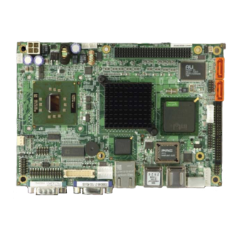
Epic sbc with intel celeron m 1ghz zero cache processor on board with vga/lvds, lan, sata and audio
Hide thumbs
Also See for NANO-8522:
- User manual (249 pages) ,
- Quick installation manual (9 pages) ,
- Quick installation manual (10 pages)
Table of Contents
Advertisement
Quick Links
Download this manual
See also:
User Manual
Advertisement
Chapters
Table of Contents

Related Manuals for IEI Technology NANO-8522


Summary of Contents for IEI Technology NANO-8522
- Page 1 NANO-8522 Motherboard...
- Page 2 REVISION HISTORY Title NANO-8522 Celeron M Board Revision Number Description Date of Issue Initial release June 2006 COPYRIGHT NOTICE The information in this document is subject to change without prior notice in order to improve reliability, design and function and does not represent a commitment on the part of the manufacturer.
-
Page 3: Table Of Contents
NANO-8522 Motherboard Table of Contents INTRODUCTION....................15 NANO-8522B ................ 16 OARD VERVIEW 1.1.1 NANO-8522 Board Variations ................. 16 1.1.2 NANO-8522 Board Benefits................16 1.1.3 NANO-8522 Board Features................16 NANO-8522 B ............... 18 OARD VERVIEW 1.2.1 NANO-8522 Board Connectors ............... 19 1.2.2 Technical Specifications................... - Page 4 2.17.1 Package Contents................... 34 CONNECTORS AND JUMPERS ................. 37 .............. 38 ERIPHERAL NTERFACE ONNECTORS 3.1.1 NANO-8522 Board Layout................38 3.1.2 Peripheral Interface Connectors ..............39 3.1.3 Rear Panel Connectors ..................40 3.1.4 Onboard Jumpers..................... 41 ..............41 NTERNAL ERIPHERAL ONNECTORS 3.2.1 4-bit GPIO Connector..................
- Page 5 NANO-8522 Motherboard 3.3.4 USB Connectors....................69 3.3.5 VGA Connector ....................69 ................... 70 NBOARD UMPERS 3.4.1 CF Card Setup ....................71 3.4.2 Clear CMOS Jumper..................72 3.4.3 COM2 Selector....................73 3.4.4 LCD Voltage Selector..................73 3.4.5 PC/104+ Selector..................... 74 INSTALLATION AND CONFIGURATION ............75 ...............
- Page 6 5.1.3 Getting Help..................... 89 5.1.4 Unable to Reboot After Configuration Changes..........89 5.1.5 BIOS Menu Bar....................89 ......................... 90 ......................91 DVANCED 5.3.1 CPU Configuration..................92 5.3.2 IDE Configuration ................... 94 5.3.2.1 IDE Master, IDE Slave ................97 5.3.3 Floppy Configuration..................101 5.3.4 Super IO Configuration..................
- Page 7 NANO-8522 Motherboard 6.6.2 Installation Steps under Existing Windows XP ..........165 BIOS CONFIGURATION OPTIONS ..............167 BIOS C ..............168 ONFIGURATION PTIONS WATCHDOG TIMER ..................173 ....................174 AH – 6FH Sub-function: ADDRESS MAPPING..................177 IO A .................... 178 DDRESS MB M ..............
- Page 8 List of Figures Figure 1-1: NANO-8522 Board Overview (Top View) ..........18 Figure 1-2: NANO-8522 Board Overview (Bottom View) .........18 Figure 2-1: Data Flow Block Diagram................27 Figure 3-1: Connector and Jumper Locations (Top Side)........38 Figure 3-2: Connector and Jumper Locations (Solder Side)........39 Figure 3-3: 4-bit GPIO Connector Location ..............42...
- Page 9 NANO-8522 Motherboard Figure 3-27: RJ-45 Ethernet Connector ..............68 Figure 3-28 Jumper ....................70 Figure 3-29: Jumper Locations..................71 Figure 4-1: Make sure the CPU socket retention screw is unlocked .....80 Figure 4-2: Lock the CPU Socket Retention Screw ..........81 Figure 4-3: IEI CF-479B-RS Cooling Kit ..............81 Figure 4-4: Securing the Cooling Kit.................82...
- Page 10 List of Tables Table 1-1: NANO-8522 Board Variations..............16 Table 1-2: Technical Specifications ................21 Table-2-1: Supported CPUs..................24 Table 2-2: Power Consumption .................34 Table 2-3: Power Consumption .................34 Table 3-1: Peripheral Interface Connectors..............40 Table 3-2: Peripheral Interface Connectors..............41 Table 3-3: Onboard Jumpers ..................41 Table 3-4: 4-bit GPIO Connector Pinouts..............42...
- Page 11 NANO-8522 Motherboard Table 3-25: RJ-45 Ethernet Connector Pinouts............67 Table 3-26: RJ-45 Ethernet Connector LEDs............68 Table 3-27: Serial Port Pinouts ..................69 Table 3-28: USB1 Connector Pinouts................69 Table 3-29: USB2 Connector Pinouts................69 Table 3-30: VGA Connector Pinouts .................70 Table 3-31: JP1 Jumper Settings................72 Table 3-32: JP4 Jumper Settings................72...
- Page 12 List of BIOS Menus Menu 1: Main ....................90 Menu 2: Advanced ....................92 Menu 3: CPU Configuration ..................93 Menu 4: IDE Configuration ..................94 Menu 5: IDE Master and IDE Slave Configuration ...........97 Menu 6: Floppy Configuration ................101 Menu 7: Super IO Configuration ................103 Menu 8: Hardware Health Configuration ...............
- Page 13 NANO-8522 Motherboard Glossary AC ’97 Audio Codec 97 L1 Cache Level 1 Cache ACPI Advanced Configuration and Power L2 Cache Level 2 Cache Interface Liquid Crystal Display Advanced Power Management Parallel Port Connector ARMD ATAPI Removable Media Device LVDS Low Voltage Differential Signaling...
- Page 14 THIS PAGE IS INTENTIONALLY KEPT BLANK ® Technology, Corp. 0-14...
-
Page 15: Introduction
NANO-8522 Motherboard Chapter Introduction 0-15... -
Page 16: Nano-8522Board Overview
NANO-8522Board Overview The EPIC form factor NANO-8522 Intel Petium M / Celeron M Socket 479 embedded board is fully equipped with a high performance processor and advanced multi-mode I/Os. The NANO-8522 is designed for system manufacturers, integrators, and VARs that want performance, reliability, and quality at a reasonable price. - Page 17 NANO-8522 Motherboard Supports dual independent displays, CRT/LCD display and 36-bit LVDS flat panel screens Supports PCI-104 extension slot Complete I/O support with 2 x SATA-150 connectors 6 x USB 2.0 connectors 1 x Parallel port connector 1 x CFII connector...
-
Page 18: Nano-8522 Board Overview
NANO-8522 Board Overview Figure 1-1: NANO-8522 Board Overview (Top View) Figure 1-2: NANO-8522 Board Overview (Bottom View) ® Technology, Corp. 0-18... -
Page 19: Nano-8522 Board Connectors
1 x RJ-45 Ethernet connector 4 x USB 2.0 ports 1 x Keyboard/Mouse connector The location of these connectors on the NANO-8522 can be seen in Figure 1-1 and Figure 1-2. These connectors are fully described in Chapter 3 Connectors and Jumpers. -
Page 20: Technical Specifications
1.2.2 Technical Specifications NANO-8522 board technical specifications are listed in Table 1-2. Detailed descriptions of each specification can be found in Chapter 2 Detailed Specifications. SPECIFICATION ® ® CPUs Supported Intel Pentium M Socket 479, ® ® Intel Celeron M Socket 479, or Intel ®... -
Page 21: Table 1-2: Technical Specifications
NANO-8522 Motherboard Ethernet Intel 82541PI for GbE / Intel 82551ER for 10/100Mbps BIOS AMI flash BIOS Physical Dimensions 115mm x 165mm (width x length) Weight GW: 1.1 Kg NW: 0.95 Kg Operating Temperature Minimum: 0ºC (32°F) Maximum: 60°C (140°F) Audio Interfaces AC ‘97 Codec Realtek ALC655... - Page 22 THIS PAGE IS INTENTIONALLY KEPT BLANK ® Technology, Corp. 0-22...
-
Page 23: Detailed Specifications
NANO-8522 Motherboard Chapter Detailed Specifications 0-23... -
Page 24: Cpu Support
CPU Support Table-2-1 lists the CPUs supported by the NANO-8522 board. Model Clock Speed L2 Cache Max. FSB Socket ® ® 1.30 to 1.70 GHz 1 MB 400 MHz Intel Pentium ® ® 1.20 to 1.73 GHz 1 MB 400 MHz... -
Page 25: Onboard Chipsets
NANO-8522 Motherboard Onboard Chipsets 2.2.1 Northbridge and Southbridge Chipsets The following chipsets are preinstalled on the board: Northbridge: Intel® 852GM Southbridge: Intel® ICH4 The following two sections (Section 2.2.2 and Section 2.2.3) list some of the features of the Intel® 852GM and the Intel® ICH4 chipsets. For more information on these two chipsets please refer to the Intel website. - Page 26 PCI Local Bus Specification, Revision 2.2-compliant with support for 33 MHz PCI operations. PCI slots (supports up to 6 Req/Gnt pairs) ACPI Power Management Logic Support Enhanced DMA controller, Interrupt controller, and timer functions Integrated IDE controller supports Ultra ATA100/66/33 USB host interface with support for six USB ports;...
-
Page 27: Data Flow
NANO-8522 Motherboard Data Flow Figure 2-1 shows the data flow between the two onboard chipsets and other components installed on the NANO-8522 and described in the following sections of this chapter. Figure 2-1: Data Flow Block Diagram 0-27... -
Page 28: Graphics Support
Graphics Support The Intel® is integrated on the Intel® 852GM Northbridge chipset. The Extreme Graphics 2 Intel® Extreme Graphics 2 features are listed below. Enhanced Rapid Pixel and Texel Rendering: Optimized visual quality and performance from the addition of hardware to support of texel formatting, bicubic filter, color blending accuracy, and video mixing render, resulting in optimized visual quality and performance. -
Page 29: Memory Support
Dual DVO ports for up to QXGA digital display support Multiple display types (LVDS, DVI, TV-out, CRT) Memory Support The NANO-8522 supports one 200-pin 266MHz or 200MHz DDR SDRAM SODIMM with a maximum capacity of 1GB. PCI Bus Interface Support The PCI bus on the NANO-8522 board has the following feature: 33MHz Revision 2.2 is implemented... -
Page 30: 10/100/1000 Base-T Internet
Automatic link speed switching from 1000Mb/s down to 10 or 100Mb/s in standby IDE Device Support The NANO-8522 southbridge chipset IDE controller supports up to two HDDs with the following specifications: Supports PIO IDE transfers up to 16MB/s Supports Ultra ATA/33 devices with data transfer rates up to 33MB/s ®... -
Page 31: Sata Drive Support
The NANO-8522 board has six USB interfaces, two internal and four external. The USB interfaces support USB 2.0. 2.13 BIOS The NANO-8522 board uses a licensed copy of AMI BIOS. The features of the flash BIOS used are listed below: SMIBIOS (DMI) compliant... -
Page 32: Audio Codec
NANO-8522. 2.15 Audio Codec The NANO-8522 has an integrated REALTEK ALC655 CODEC. The ALC655 CODEC is a 16-bit, full-duplex AC'97 Rev. 2.3 compatible six-channel audio CODEC designed for PC multimedia systems, including host/soft audio and AMR/CNR-based designs. Some of the features of the codec are listed below. -
Page 33: Power Consumption
Configuration Panel for improved user convenience 2.16 Power Consumption Table 2-2 shows the power consumption parameters for the NANO-8522 when a zero cache ULV Celeron M CPU is running with a clock speed of 800MHz and a 256MB 266MHz DDR. -
Page 34: Packaged Contents And Optional Accessory Items
Voltage Current +12V 0.85A Table 2-2: Power Consumption Table 2-3 shows the power consumption parameters for the NANO-8522 when a Pentium CPU is running with a clock speed of 1.7GHz and a 512MB 266MHz DDR. Voltage Current +12V 3.5A Table 2-3: Power Consumption 2.17 Packaged Contents and Optional Accessory Items... - Page 35 NANO-8522 Motherboard USB cable LPT cable RS232/422/485 cable 0-35...
- Page 36 THIS PAGE IS INTENTIONALLY KEPT BLANK ® Technology, Corp. 0-36...
-
Page 37: Connectors And Jumpers
NANO-8522 Motherboard Chapter Connectors and Jumpers 0-37... -
Page 38: Peripheral Interface Connectors
The locations of the peripheral interface connectors are shown in Section 3.1.1. A complete list of all the peripheral interface connectors can be seen in Section 3.1.2. 3.1.1 NANO-8522 Board Layout Figure 3-1 and Figure 3-2 shows the onboard peripheral connectors, rear panel peripheral connectors and onboard jumpers. -
Page 39: Peripheral Interface Connectors
Figure 3-2: Connector and Jumper Locations (Solder Side) 3.1.2 Peripheral Interface Connectors Table 3-1 shows a list of the peripheral interface connectors on the NANO-8522 board. Detailed descriptions of these connectors can be found in section 3.2 on page 41. -
Page 40: Rear Panel Connectors
USB 2.0 internal USB connector 8-pin header USB3 Table 3-1: Peripheral Interface Connectors 3.1.3 Rear Panel Connectors Table 3-2 lists the rear panel connectors on the NANO-8522 board. Detailed descriptions of these connectors can be found in Section 3.3on page 66. Connector Type Label... -
Page 41: Onboard Jumpers
Internal peripheral connectors are found on the board and are only accessible when the board is outside of the chassis. This section has complete descriptions of all the internal, peripheral connectors on the NANO-8522 board. 3.2.1 4-bit GPIO Connector CN Label:... -
Page 42: Atx Power Button Connector
The General Purpose Input/Output (GPIO) connector connects external devices. The GPIO connector provides a set of configurable IO ports for either input or output. PIN NO. DESCRIPTION PIN NO. DESCRIPTION OUT0 OUT1 OUT2 OUT3 Table 3-4: 4-bit GPIO Connector Pinouts Figure 3-3: 4-bit GPIO Connector Location 3.2.2 ATX Power Button Connector CN Label:... -
Page 43: Atx Power Connector
NANO-8522 Motherboard PIN NO. DESCRIPTION Button 1 Button 2 Table 3-5: Power Button Connector Pinouts Figure 3-4: Power Button Connector Location 3.2.3 ATX Power Connector CN Label: CN Type: 1x3 pin header CN Location: See Figure 3-5 CN Pinouts: See Table 3-6 This connector supports the ATX power supply. -
Page 44: Audio Connector
CN Label: AUDIO1 CN Type: 2x5 pin headers CN Location: See Figure 3-6 CN Pinouts: See Table 3-7 The NANO-8522 has a built-in AC ’97 AUDIO CODEC connector directly connected to the MIC-IN, LINE-IN and LINE-OUT. ® Technology, Corp. 0-44... -
Page 45: Battery Connector
NANO-8522 Motherboard PIN NO. DESCRIPTION PIN NO. DESCRIPTION LINE_OUT-R LINE_IN-R LINE_OUT-L LINE_IN-L MIC-IN Table 3-7: Audio Connector Pinouts Figure 3-6: Audio Connector Location 3.2.5 Battery Connector CN Label: CN Type: 1x2 pin header CN Location: See Figure 3-7 The battery connector is connected to a preinstalled VARTA CR2032 3V battery... -
Page 46: Power Connector
CN Type: 1x4 pin header CN Location: See Figure 3-8 CN Pinouts: See Table 3-8 Connects a power source from a power supply unit (PSU) to the NANO-8522. PIN NO. DESCRIPTION VCC12 VCC12 Table 3-8: 12V Power Connector Pinouts ®... -
Page 47: Compact Flash Type 2 Socket
CN Pinouts: See Table 3-9 A CFII (compact flash type II connector) is located on the solder side of the NANO-8522. The CFII connector is for applications without external storage. The Compact Flash socket provides an alternative to hard disk drives in applications where hard disk drives may consume too much space and storage capacity is not a requirement. -
Page 48: Figure 3-9: Cfii Socket Location (Solder Side)
HDC_CS0# HDC_CS1 GROUND IOR# IOW# INTERRUPT VCC_COM VCC_COM CSEL HDD_RESET IORDY VCC_COM HDD_ACTIVE# DATA 0 DATA 1 DATA 8 DATA 2 DATA 9 DATA 10 VCC-IN CHECK2 GROUND Table 3-9: CFII Socket Pinouts Figure 3-9: CFII Socket Location (Solder Side) ®... -
Page 49: Ddr Sodimm Socket
CN Location: See Figure 3-10 A 200 pin DDR-SDRAM SODIMM socket is located on the rear side of the NANO-8522 board. The SODIMM socket can support 266MHz DDR SODIMM SDRAM of up to 1GB. Figure 3-10: SODIMM Socket Location (Solder Side) 3.2.9 Fan Connector... -
Page 50: Ide Interface Connector
system BIOS can recognize the fan speed. Please note that only specified fans can issue the rotation signals. PIN NO. DESCRIPTION Fan Speed Detect +12V Table 3-10: Fan Connector Pinouts Figure 3-11: Fan Connector Location 3.2.10 IDE Interface Connector CN Label: IDE1 CN Type: 2x22 pin header... -
Page 51: Table 3-11: Ide Connector Pinouts
NANO-8522 Motherboard PIN NO. DESCRIPTION PIN NO. DESCRIPTION RESET# GROUND DATA 7 DATA 8 DATA 6 DATA 9 DATA 5 DATA 10 DATA 4 DATA 11 DATA 3 DATA 12 DATA 2 DATA 13 DATA 1 DATA 14 DATA 0... -
Page 52: Inverter Connector
Figure 3-12: IDE Connector Location 3.2.11 Inverter Connector CN Label: CN Type: 1x5 pin headers CN Location: See Figure 3-13 CN Pinouts: See Table 3-12 The inverter connector connects to the LCD backlight inverter. PIN NO. DESCRIPTION BKLTCTL +12V BKLEN Table 3-12: Inverter Connector Pinouts ®... -
Page 53: Ir Interface Connector
NANO-8522 Motherboard Figure 3-13: Inverter Connector Location 3.2.12 IR Interface Connector CN Label: CN Type: 1x5 pin headers CN Location: See Figure 3-14 CN Pinouts: See Table 3-13 The integrated infrared (IrDA) connector supports both Serial Infrared (SIR) and Amplitude Shift Key Infrared (ASKIR) interfaces. -
Page 54: Keyboard/Mouse Connector
KBMS1 CN Type: 1x6 pin header CN Location: See Figure 3-15 CN Pinouts: See Table 3-14 The Keyboard/PS2 mouse cable shipped with the NANO-8522 board is connected to the keyoard/mouse connector. PIN NO. DESCRIPTION VCC5 MOUSE DATA MOUSE CLOCK KEYBOARD DATA... -
Page 55: Led Connector
NANO-8522 Motherboard Figure 3-15: Keyboard/Mouse Connector Location 3.2.14 LED Connector CN Label: CN Type: 1x6 pin header CN Location: See Figure 3-16 CN Pinouts: See Table 3-15 This connector connects to the LED lights indicating the hard drive activity and the power status. -
Page 56: Lvds Connector
Figure 3-16: LED Connector Location 3.2.15 LVDS Connector CN Label: LVDS1 CN Type: DF 13 CN Location: See Figure 3-17 CN Pinouts: See Table 3-16 LVDS (Low Voltage Differential Signaling) is a low noise, low power, and low amplitude method for high-speed data transmission over a copper wire. The LVDS connector is typically connected to an LCD screen. -
Page 57: Parallel Port Connector
NANO-8522 Motherboard BYCLK- BYCLK+ BY3- BY3+ LCDVCC LCDVCC LCDVCC LCDVCC Table 3-16: LVDS Connector Pinouts Figure 3-17: LVDS Connector 3.2.16 Parallel Port Connector CN Label: LPT1 CN Type: 2x13 pin header CN Location: See Figure 3-18 CN Pinouts: See Table 3-17 The parallel port connector is usually connected to a printer. -
Page 58: Figure 3-18: Parallel Port Connector Location
DATA0 ERROR# DATA1 INITIALIZE# DATA2 PRINTER SELECT LN# DATA3 DATA4 DATA5 DATA6 DATA7 ACKNOWLEDGE# BUSY PAPER EMPTY PRINTER SELECT Table 3-17: Parallel Port Connector Pinouts Figure 3-18: Parallel Port Connector Location ® Technology, Corp. 0-58... -
Page 59: Pc/104+ Connector
NANO-8522 Motherboard 3.2.17 PC/104+ Connector CN Label: CN Type: 4x30 pin PCI slot CN Location: See Figure 3-19 CN Pinouts: See Table 3-18 This connector supports the PC/104+ module. Description Description Description Description GROUND NC/SERIRQ CBE0- AD11 AD10 N66EV AD14... -
Page 60: Reset Connector
GNT1- GNT2- PCICLK0 PCICLK1 PCICLK2 PCICLK3 INTD- PCIRST- +12V INTA- INTB- INTC- -12v REQ3- GNT3- GND/3.3V Table 3-18: PC/104+ Connector Pinouts Figure 3-19: PC/104+ Connector Location 3.2.18 Reset Connector CN Label: RST1 CN Type: 1x2 pin header CN Location: See Figure 3-20 CN Pinouts: See Table 3-19 ®... -
Page 61: Sata Connectors
NANO-8522 Motherboard PIN NO. DESCRIPTION Reset 1 Reset 2 Table 3-19: Reset Connector Pinouts Figure 3-20: Reset Connector Location 3.2.19 SATA Connectors CN Label: S_ATA1, S_ATA2 CN Type: 1x7 pin header CN Location: See Figure 3-21 CN Pinouts: See Table 3-20... -
Page 62: Serial Port2 Connector
The NANO-8522 provides two first-generation SATA ports to connect with SATA drives. The SATA drives transmit data at speeds up to 150MB/s. PIN NO. DESCRIPTION TX0+ TX0- RX0- RX0+ Table 3-20: SATA Connector Pinouts Figure 3-21: SATA Connector Location 3.2.20 Serial Port2 Connector... -
Page 63: Serial Port3 Connector
NANO-8522 Motherboard PIN NO. DESCRIPTION PIN NO. DESCRIPTION DCD# DSR# RTS# CTS# DTR# TxD485+ TxD485- RxD485+ RxD485- Table 3-21: COM2 Connector Pinouts Figure 3-22: COM2 Connector Location 3.2.21 Serial Port3 Connector CN Label: COM3 CN Type: 2x5 pin header CN Location:... -
Page 64: Serial Port4 Connector
PIN NO. DESCRIPTION PIN NO. DESCRIPTION DCD# DSR# RTS# CTS# DTR# Table 3-22: COM3 Connector Pinouts Figure 3-23: COM3 Connector Location 3.2.22 Serial Port4 Connector CN Label: COM4 CN Type: 2x5 pin header CN Location: See Figure 3-24 CN Pinouts: See Table 3-23 ®... -
Page 65: Usb Connector
NANO-8522 Motherboard PIN NO. DESCRIPTION PIN NO. DESCRIPTION DCD# DSR# RTS# CTS# DTR# Table 3-23: COM4 Connector Pinouts Figure 3-24: COM4 Connector Location 3.2.23 USB Connector CN Label: USB3 CN Type: 2x4 pin header CN Location: See Figure 3-25 CN Pinouts: See Table 3-24 Two USB devices can be connected directly to the onboard USB connector. -
Page 66: External (Rear Panel) Connectors
External (Rear Panel) Connectors Figure 3-26 shows the NANO-8522 board rear panel. The peripheral connectors on the back panel can be connected to devices externally when the NANO-8522 is installed in a chassis. The peripheral connectors on the rear panel are:... -
Page 67: Ethernet Connector
CN Pinouts: See Table 3-25 The NANO-8522 is equipped with LAN 10/100/1000-TX Ethernet controller. The Ethernet connector can be directly connected to a Local Area Network (LAN) through a network hub. An RJ-45 Ethernet connector is shown in Figure 3-27. -
Page 68: Keyboard/Mouse Connector
Figure 3-27: RJ-45 Ethernet Connector The RJ-45 Ethernet connector has two status LEDs, one green and one yellow. The green LED indicates activity on the port and the yellow LED indicates the port is linked. See Table 3-26. DESCRIPTION STATUS DESCRIPTION STATUS GREEN... -
Page 69: Usb Connectors
NANO-8522 Motherboard Table 3-27: Serial Port Pinouts 3.3.4 USB Connectors CN Label: USB1, USB2 CN Type: USB port CN Location: See Figure 3-26 (labeled number 4 & 5) CN Pinouts: See Table 3-28, Table 3-29 USB devices can be connected directly to the USB connectors on the rear panel. -
Page 70: Onboard Jumpers
OPEN a jumper means removing the Figure 3-28 Jumper plastic clip from a jumper. The NANO-8522 board has the following four onboard jumpers: ® Technology, Corp. 0-70... -
Page 71: Cf Card Setup
NANO-8522 Motherboard CF card setup (JP1) Clear CMOS (JP4) COM2 RS232/RS422/RS485 selector (JP2) LCD Voltage selector (JP6) PC104+ SERIRQ net to CN3 pin B1 selector (JP5) Figure 3-29: Jumper Locations 3.4.1 CF Card Setup Jumper Label: Jumper Type: 2-pin header... -
Page 72: Clear Cmos Jumper
Jumper Location: See Figure 3-29 If the NANO-8522 fails to boot due to improper BIOS setting, use this jumper to clear the CMOS data and reset the system BIOS information. To do this, use the jumper cap to close pins 2 and 3 for a few seconds then reinstall the jumper clip back to pins 1 and 2. -
Page 73: Com2 Selector
NANO-8522 Motherboard 3.4.3 COM2 Selector Jumper Label: Jumper Type: 6-pin header Jumper Settings: See Table 3-33 Jumper Location: See Figure 3-29 DESCRIPTION 1-2 closed RS232 (default) 3-4 closed RS422 5-6 closed RS485 Table 3-33: JP2 Jumper Settings 3.4.4 LCD Voltage Selector... -
Page 74: Pc/104+ Selector
3.4.5 PC/104+ Selector Jumper Label: Jumper Type: 2-pin header Jumper Settings: See Table 3-35 Jumper Location: See Figure 3-29 DESCRIPTION Open Disconnect (default) Close Connect Table 3-35: JP5 Jumper Settings ® Technology, Corp. 0-74... -
Page 75: Installation And Configuration
NANO-8522 Motherboard Chapter Installation and Configuration 0-75... -
Page 76: Installation Considerations
NANO-8522 and injury to the person installing the NANO-8522. 4.1.1 Installation Notices Before and during the installation of the NANO-8522 board, please do the following: Read the user manual The user manual provides a complete description of the NANO-8522 board, installation instructions and configuration options. -
Page 77: Unpacking
4.2.1 Unpacking Precautions Before installing the NANO-8522 board, unpack the board first. Some components on NANO-8522 are very sensitive to static electricity and can be damaged by a sudden rush of power. To protect it from being damage, follow these precautions: The user should ground themselves to remove any static charge before touching the NANO-8522. -
Page 78: Nano-8522 Board Installation
WARNING! Please note that the installation instructions described in this manual should be carefully followed in order to avoid damage to the NANO-8522 components and injury to the body. WARNING! When installing electronic components onto the NANO-8522 always take the... -
Page 79: Components To Install
NANO-8522 Motherboard Northbridge heat sink Southbridge heat sink 4.3.2 Components to Install To install the NANO-8522, the following components must be installed or connected to the NANO-8522. CPU (Intel Celeron M 800MHz for NANO-8522E-800Z-R10) DIMM modules Compact flash device Peripheral devices 4.3.3 CPU Installation... -
Page 80: Figure 4-1: Make Sure The Cpu Socket Retention Screw Is Unlocked
Figure 4-1: Make sure the CPU socket retention screw is unlocked Inspect the CPU socket Make sure there are no bent pins and make sure the Step 2: socket contacts are free of foreign material. If any debris is found, remove it with compressed air. -
Page 81: Cooling Kit (Cf-479B-Rs) Installation
NANO-8522 Motherboard Figure 4-2: Lock the CPU Socket Retention Screw 4.3.4 Cooling Kit (CF-479B-RS) Installation Figure 4-3: IEI CF-479B-RS Cooling Kit IEI provides a cooling kit designed for socket 479 CPUs. (See Figure 4-3) The cooling kit is comprised of a CPU heatsink and a cooling fan. -
Page 82: Figure 4-4: Securing The Cooling Kit
NOTE: The CF-479B-RS heatsink comes with a sprayed layer of thermal paste. Make sure not to accidentally wipe away the thermal paste while unpacking or installing the heatsink. Thermal paste between the CPU and the heatsink is important for optimum heat dissipation. To install the CF-479B-RS cooling kit, please follow the steps below. -
Page 83: Dimm Module Installation
The maximum SODIMM capacity supported is 1GB The maximum SODIMM frequency supported is 266MHz. The SODIMM chip must be a 200-pin memory chip 4.3.5.2 DIMM Module Installation The NANO-8522 board has one 200-pin SODIMM socket. To install the SODIMM module, follow the instructions below. 0-83... -
Page 84: Peripheral Device Connection
Table 4-1: IEI Provided Cables 4.3.6.1 IDE Disk Drive Connector (IDE1) The cable used to connect the NANO-8522 to the IDE HDD is a standard 44-pin ATA/33 flat cable. To connect an IDE device to the NANO-8522, follow the instructions below. -
Page 85: Keyboard/Mouse Connection
4.3.6.2 Keyboard/Mouse Connection The cable used to connect the NANO-8522 to the keyboard and mouse is Y-cable that is connected to KBMS1. To connect a keyboard and mouse, please do the following. Insert the connector at the end of the keyboard/mouse cable in the Step 2: keyboard/mouse connector on the NANO-8522. -
Page 86: Ethernet Connection
4.5.2 Ethernet Connection The rear panel RJ-45 connectors can be connected to an external LAN and communicate with data transfer rates up to 1000M/s. 4.5.3 USB Connection The rear panel USB connectors provide easier and quicker access to external USB devices. -
Page 87: Ami Bios Setup
NANO-8522 Motherboard Chapter AMI BIOS Setup 0-87... -
Page 88: Introduction
Introduction A licensed copy of AMI BIOS is preprogrammed into the ROM BIOS. The BIOS setup program allows users to modify the basic system configuration. This chapter describes how to access the BIOS setup program and the configuration options that may be changed. -
Page 89: Getting Help
NANO-8522 Motherboard F1 key General help, only for Status Page Setup Menu and Option Page Setup Menu F2 /F3 key Change color from total 16 colors. F2 to select color forward. F10 key Save all the CMOS changes, only for Main Menu Table 5-1: BIOS Navigation Keys 5.1.3 Getting Help... -
Page 90: Main
Main The Main BIOS menu (BIOS Menu 1) appears when the BIOS Setup program is entered. The Main menu gives an overview of the basic system information. BIOS Menu 1: Main System Overview The System Overview lists a brief summary of different system components. The fields in System Overview cannot be changed. -
Page 91: Advanced
NANO-8522 Motherboard Type: Names the currently installed processor Speed: Lists the processor speed Count: The number of CPUs on the motherboard System Memory: Displays the auto-detected system memory. Size: Lists memory size The System Overview field also has two user configurable fields: System Time [xx:xx:xx] Use the System Time option to set the system time. -
Page 92: Cpu Configuration
Smbios Configuration (see Section 5.3.8) USB Configuration (see Section 5.3.9) BIOS Menu 2: Advanced 5.3.1 CPU Configuration Use the CPU Configuration menu (BIOS Menu 3) to view detailed CPU specifications and configure the CPU. ® Technology, Corp. 0-92... -
Page 93: Hyper Threading Technology [Enabled]
NANO-8522 Motherboard BIOS Menu 3: CPU Configuration The CPU Configuration menu (BIOS Menu 3) lists the following CPU details: Manufacturer: Lists the name of the CPU manufacturer Brand String: Lists the brand name of the CPU being used Frequency: Lists the CPU processing speed... -
Page 94: Ide Configuration
5.3.2 IDE Configuration Use the IDE Configuration menu (BIOS Menu 4) to change and/or set the configuration of the IDE devices installed in the system. BIOS Menu 4: IDE Configuration OnBoard PCI IDE Controller [Both] Use the OnBoard PCI IDE Controller BIOS option to specify the IDE channels used by the onboard PCI IDE controller. -
Page 95: Onboard Pci Ide Mode [Legacy Mode]
NANO-8522 Motherboard Primary Slave Only allows the system to detect the Secondary IDE Secondary channel, including both the Secondary Master and Secondary Slave Allows the system to detect both the Primary and Both EFAULT Secondary IDE channels including the Primary Master, Primary Slave, Secondary Master and Secondary Slave. -
Page 96: Ata (Pi) 80Pin Cable Detection [Host & Device]
25 seconds 30 seconds 35 seconds (Default) The best setting to use if the onboard IDE controllers are set to a specific IDE disk drive in the AMI BIOS is “0 seconds” and a large majority of ultra ATA hard disk drives can be detected well within “35 seconds”... -
Page 97: Ide Master, Ide Slave
NANO-8522 Motherboard Secondary IDE Master Secondary IDE Slave The IDE Configuration menu (BIOS Menu 4) allows changes to the configurations for the IDE devices installed in the system. If an IDE device is detected, and one of the above listed four BIOS configuration options are selected, the IDE configuration options shown in Section 5.3.2.1 appear. -
Page 98: Auto-Detected Drive Parameters
Auto-Detected Drive Parameters The “grayed-out” items in the left frame are IDE disk drive parameters automatically detected from the firmware of the selected IDE disk drive. The drive parameters are listed as follows: Type: Lists the device type (e.g. hard disk, CD-ROM etc.) LBA Mode: Indicates whether the LBA (Logical Block Addressing) is a method of addressing data on a disk drive is supported or not. -
Page 99: Zip
NANO-8522 Motherboard This option specifies an ATAPI Removable Media ARMD Device. These include, but are not limited to: LS-120 LBA/Large Mode [Auto] Use the LBA/Large Mode option to disable or enable BIOS to auto detects LBA (Logical Block Addressing). LBA is a method of addressing data on a disk drive. In LBA mode, the maximum drive capacity is 137 GB. -
Page 100: Pio Mode [Auto]
PIO Mode [Auto] Use the PIO Mode option to select the IDE PIO (Programmable I/O) mode program timing cycles between the IDE drive and the programmable IDE controller. As the PIO mode increases, the cycle time decreases. Auto BIOS auto detects the PIO mode. Use this value if the IDE disk EFAULT drive support cannot be determined. -
Page 101: Floppy Configuration
NANO-8522 Motherboard Allows BIOS to use the HDD SMART feature Enabled 32Bit Data Transfer [Disabled] Use the 32Bit Data Transfer BIOS option to enables or disable 32-bit data transfers. Disabled Prevents the BIOS from using 32-bit data transfers. EFAULT Enabled Allows BIOS to use 32-bit data transfers on supported hard disk drives. -
Page 102: Super Io Configuration
Floppy A [Disabled] The Floppy A configuration option determines the types of the floppy drive installed in the system. The following configuration options are available. Disabled (default) 360 KB 5¼” 1.2 MB 5¼” 720 KB 3 ½” 1.44 MB 3½” 2.88 MB 3½”... -
Page 103: On Board Floppy Controller [Enabled]
NANO-8522 Motherboard BIOS Menu 7: Super IO Configuration On Board Floppy Controller [Enabled] Disabled Allows BIOS to disable the floppy controller Enabled Allows BIOS to enable the floppy controller EFAULT Serial Port1 Address [3F8/IRQ4] Use the Serial Port1 Address option to select the Serial Port 1 base address. -
Page 104: Serial Port2 Address [2F8/Irq3]
address is IRQ3 Serial Port2 Address [2F8/IRQ3] Use the Serial Port2 Address option to select the Serial Port 2 base address. No base address is assigned to Serial Port 2 Disabled 2F8/IRQ3 Serial Port 2 I/O port address is 3F8 and the interrupt EFAULT address is IRQ3 3E8/IRQ4... -
Page 105: Parallel Port Mode [Normal]
NANO-8522 Motherboard Parallel Port Mode [Normal] Use the Parallel Port Mode option to select the mode the parallel port operates in. Normal The normal parallel port mode is the standard mode EFAULT for parallel port operation. Bi-directional Parallel port outputs are 8-bits long. Inputs are accomplished by reading 4 of the 8 bits on the status register. -
Page 106: Parallel Port Irq [Irq7]
Parallel Port IRQ [IRQ7] Use the Parallel Port IRQ selection to set the parallel port interrupt address. IRQ5 IRQ5 is assigned as the parallel port interrupt address IRQ7 IRQ7 is assigned as the parallel port interrupt address EFAULT Serial Port3 Address [3E8] Use the Serial Port3 Address option to select the base addresses for serial port 3 Disabled No base address is assigned to serial port 3... -
Page 107: Hardware Health Configuration
NANO-8522 Motherboard No base address is assigned to serial port 3 Disabled Serial port 4 I/O port address is 3F8 Serial port 4 I/O port address is 2F8 Serial port 4 I/O port address is 3E8 Serial port 4 I/O port address is 2E8... - Page 108 BIOS Menu 8: Hardware Health Configuration The following system parameters and values are shown. The system parameters that are monitored are: System Temperatures: The following system temperatures are monitored System Temperature CPU Temperature Voltages: The following system voltages are monitored Vcore AVCC 3VCC...
-
Page 109: Acpi Configuration
NANO-8522 Motherboard +3.3V +2.5V VBAT 5.3.6 ACPI Configuration The ACPI Configuration menu (BIOS Menu 9) configures the Advanced Configuration and Power Interface (ACPI) and Power Management (APM) options. BIOS Menu 9: ACPI Configuration 5.3.6.1 General ACPI Configuration Use the General ACPI Configuration menu (BIOS Menu 10) to select the ACPI state when the system is suspended. -
Page 110: Suspend Mode [Auto]
BIOS Menu 10: General ACPI Configuration Suspend Mode [Auto] Use the Suspend Mode option to specify the sleep state the system enters when it is not being used. S1 (POS) The system enters S1(POS) sleep state. The system appears off. The CPU is stopped; RAM is refreshed; the system is running in a low power mode. -
Page 111: Advanced Acpi Configuration
NANO-8522 Motherboard Repost Video on S3 Resume [No] Use the Repost Video on S3 Resume to determine whether the VGA BIOS post will be invoked after the system is roused from an S3 (STR) suspend state. The VGA BIOS post is not invoked... -
Page 112: Acpi 2.0 Features [No]
ACPI 2.0 Features [No] Use the ACPI 2.0 Features option to enable the ACPI (Advanced Configuration and Power Interface) features. By enabling this feature the system RSDP (Root System Description Pointer) is able to obtain physical addresses for other 64-bit fixed system description tables. -
Page 113: Chipset Acpi Configuration
NANO-8522 Motherboard Pointers to the AMI OEMB table are provided in the Enabled EFAULT RSDT and the XSDT Headless Mode [Disabled] Use the Headless Mode option to update the ACPI FACP (Fixed ACPI Description Table) to indicate headless operations, i.e. a computer without a monitor, keyboard and mouse. -
Page 114: Mps Configuration
APIC ACPI SCI IRQ [Disabled] Use APIC ACPI SCI IRQ option to enable the system to send a flag report to the ACPI OS if a SCI IRQ interrupt event is made via the APIC. Disabled No flag report is sent to the ACPI OS when there is a "SCI EFAULT IRQ"... -
Page 115: Smbios Configuration
NANO-8522 Motherboard BIOS Menu 13: MPS Configuration MPS Revision [1.4] Use the Multiprocessor Specification (MPS) for OS option to specify the MPS version to be used. MPS version 1.1 is used MPS version 1.4 is used EFAULT 5.3.8 Smbios Configuration Use the Smbios Configuration menu (BIOS Menu 14) to configure SMBIOS parameters. -
Page 116: Usb Configuration
BIOS Menu 14: Smbios Configuration Smbios Smi Support [Enabled] Use the Smbios Smi Support to enable the system to support the SMBIOS SMI wrapper for the PnP function 50h – 54h. SMBIOS SMI wrapper for the PnP function 50h – 54h not Disabled supported Enabled... -
Page 117: Usb Configuration
NANO-8522 Motherboard BIOS Menu 15: USB Configuration USB Configuration The USB Configuration field shows the system USB configuration. The items listed are: Module Version: 2.24.0-11.4 USB Devices Enabled The USB Devices Enabled field lists the USB devices that are enabled on the system USB Function [6 USB Ports] Use the USB Function BIOS option to enable USB host controllers. -
Page 118: Legacy Usb Support [Enabled]
The USB controller activates 2 USB ports 2 USB Ports 4 USB Ports The USB controller activates 4 USB ports 6 USB Ports The USB controller activates 6 USB ports EFAULT Legacy USB Support [Enabled] Use the Legacy USB Support BIOS option to enable USB mouse and USB keyboard support. -
Page 119: Pci/Pnp
NANO-8522 Motherboard BIOS EHCI Handoff [Enable] Use the BIOS EHCI Handoff option for systems running OSes that do not have EHCI hand-off support. The EHCI ownership change is managed by the EHCI driver. Disabled Systems with OSes that do not support EHCI can use the EHCI handoff functionality. -
Page 120: Clear Nvram [No]
BIOS Menu 16: PCI/PnP Configuration Clear NVRAM [No] Use the Clear NVRAM option to specify if the NVRAM (Non-Volatile RAM) is cleared when the power is turned off. System does not clear NVRAM during system boot EFAULT System clears NVRAM during system boot Plug &... -
Page 121: Pci Latency Timer [64]
NANO-8522 Motherboard specifications, this option allows the BIOS to configure all the devices in the system. This setting allows the operating system to change the interrupt, I/O, and DMA settings. Set this option if the system is running Plug and Play aware operating systems. -
Page 122: Pci Ide Busmaster [Disabled]
snooping to be enabled, this option should be disabled. PCI devices are informed that an ISA based Graphics Enabled device is installed in the system so the ISA based Graphics card functions correctly. This does not necessarily indicate a physical ISA adapter card. The graphics chipset can be mounted on a PCI card. -
Page 123: Irq# [Available]
NANO-8522 Motherboard PCI IDE adapter card. Only select this slot if the adapter card is installed in PCI Slot 3. PCI Slot 4 PCI Slot 4 is selected as the location of the OffBoard PCI IDE adapter card. Only select this slot if the adapter card is installed in PCI Slot 4. -
Page 124: Boot
IRQ 15 DMA Channel# [Available] Use the DMA Channel# option to assign a specific DMA channel to a particular PCI/PnP device. Available The specified DMA is available to be used by EFAULT PCI/PnP devices Reserved The specified DMA is reserved for use by Legacy ISA devices Available DMA Channels are: DM Channel 0... -
Page 125: Boot Settings Configuration
NANO-8522 Motherboard BIOS Menu 17: Boot 5.5.1 Boot Settings Configuration Use the Boot Settings Configuration menu (BIOS Menu 18) to configure advanced system boot options. 0-12... -
Page 126: Quick Boot [Enabled]
BIOS Menu 18: Boot Settings Configuration Quick Boot [Enabled] Use the Quick Boot BIOS option to make the computer speed up the boot process. Disabled No POST procedures are skipped Enabled Some POST procedures are skipped to decrease the EFAULT system boot time Quiet Boot [Disabled] Use the Quiet Boot BIOS option to select the screen display when the system boots. -
Page 127: Addon Rom Display Mode [Force Bios]
NANO-8522 Motherboard AddOn ROM Display Mode [Force BIOS] Use the AddOn ROM Display Mode option to allow add-on ROM (read-only memory) messages to be displayed. Force BIOS The system forces third party BIOS to display EFAULT during system boot. The system displays normal information during Keep Current system boot. -
Page 128: Wait For 'F1' If Error [Enabled]
Allows the system to automatically detect if a PS/2 Auto EFAULT mouse is being used. Wait For ‘F1’ If Error [Enabled] Use the Wait For ‘F1’ if Error option to specify how the system responds when the system detects an error on boot up. If there is an error when booting up, the system does not Disabled wait for user intervention but continues to boot up in the... -
Page 129: Security
NANO-8522 Motherboard Does not allow optional ROM to trap interrupt 19 Disabled EFAULT Enabled Allows optional ROM to trap interrupt 19 Security Use the Security menu (BIOS Menu 19) to set system and user passwords. BIOS Menu 19: Security Change Supervisor Password Use the Change Supervisor Password to set or change a supervisor password. -
Page 130: Chipset
Change User Password Use the Change User Password to set or change a user password. The default for this option is Not Installed. If a user password must be installed, select this field and enter the password. After the password has been added, Install appears next to Change User Password. -
Page 131: Northbridge Configuration
NANO-8522 Motherboard BIOS Menu 20: Chipset 5.7.1 NorthBridge Configuration Use the NorthBridge Configuration menu (BIOS Menu 21) to configure the northbridge chipset. 0-13... -
Page 132: Dram Frequency [Auto]
BIOS Menu 21:NorthBridge Chipset Configuration DRAM Frequency [Auto] Use the DRAM Frequency option to specify the DRAM frequency or allow the system to automatically detect the DRAM frequency. Sets the DRAM frequency to 200MHz 200MHz Sets the DRAM frequency to 266MHz 266MHz 333MHz Sets the DRAM frequency to 333MHz... -
Page 133: Configure Dram Timing By Spd [Enabled]
NANO-8522 Motherboard Configure DRAM Timing by SPD [Enabled] Use the Configure DRAM Timing by SPD option to determine if the system uses the SPD (Serial Presence Detect) EEPROM to configure the DRAM timing. The SPD EEPROM contains all necessary DIMM specifications including the speed of the individual components such as CAS and bank cycle time as well as valid settings for the module and the manufacturer's code. -
Page 134: Init. Graphic Adapter Priority [Internal Vga]
Init. Graphic Adapter Priority [Internal VGA] The Init. Graphic Adapter Priority option selects the graphics controller the system uses as a primary boot device. The options are: Internal VGA PCI/Int-VGA Internal Graphics Mode Select [Enable, 8MB] Use the Internal Graphic Mode Select option to specify the amount of system memory that can be used by the Internal graphics device. -
Page 135: Flat Panel Type [640X480 18Bit Lvds]
NANO-8522 Motherboard Auto (Default) CRT on Port 0 LFP on Port 2 LFP on Port 3 DFP on Port 2 DFP on Port 3 TV on Port 2 TV on Port 3 CRT-Port 0 & CRT-Port 2 CRT-Port 0 & CRT-Port 3 CRT-Port 0 &... -
Page 136: Southbridge Configuration
1024x768 36bit LVDS Type 12 Type 13 Type 14 Type 15 Type 16 Local Flat Panel Scaling [Auto] The Local Flat Panel Scaling option selects the mode of the local flat panel scaling. Auto Automatically scale the connected local flat EFAULT panel. -
Page 137: Onboard Ac97 Audio Device
NANO-8522 Motherboard BIOS Menu 22:SouthBridge Chipset Configuration OnBoard AC97 Audio DEVICE The OnBoard AC97 Audio DEVICE option enables or disables the AC’97 CODEC. Auto The onboard AC’97 automatically detected and enabled EFAULT Disabled The onboard AC’97 is disabled Restore on AC Power Loss [Last State] The Restore on AC Power Loss BIOS option specifies what state the system returns to if there is a sudden loss of power to the system. -
Page 138: Power Key
Power Key The Power menu (BIOS Menu 23) allows the advanced power management options to be configured. BIOS Menu 23:Power Power Management/APM [Enabled] The Power Management/APM BIOS option allows access to the advanced power management features. If this option is disabled, the only other option on the screen is the “Resume On RTC Alarm.”... -
Page 139: Video Power Down Mode [Suspend]
NANO-8522 Motherboard Video Power Down Mode [Suspend] The Video Power Down Mode BIOS option specifies in what system mode the video device can be turned off. Disabled The Video cannot be turned off in the Suspend or Standby mode The video can be turned off in the Standby mode... -
Page 140: Suspend Time Out [Disabled]
30 Min 40 Min 50 Min 60 Min Suspend Time Out [Disabled] The Power Management/APM option must be enabled in order to change this configuration option. The Suspend Time Out option specifies what length of time without activity on certain components will place those components in a suspended state. The options are: Disabled (Default) 1 Min... -
Page 141: Keyboard & Ps/2 Mouse [Monitor]
NANO-8522 Motherboard 12.5% Keyboard & PS/2 Mouse [MONITOR] The Power Management/APM option must be enabled in order to change this configuration option. The keyboard & PS/2 mouse option enables monitoring of activity on the keyboard and PS/2 mouse ports and rouses the system from a sleep or suspend state. -
Page 142: Primary Master Ide [Monitor]
Primary master IDE [MONITOR] The Power Management/APM option must be enabled in order to change this configuration option. The Primary Master IDE option enables monitoring of activity of the primary master IDE device and rouses the system from a sleep or suspend state. Ignore The system does not monitor the primary master IDE device and does not rouse the system from a sleep or... -
Page 143: Secondary Slave Ide [Monitor]
NANO-8522 Motherboard device and does not rouse the system from a sleep or suspend state when an IRQ is detected. Monitor The system monitors the secondary master IDE device EFAULT and rouses the system from a sleep or suspend state when an IRQ is detected. -
Page 144: Resume On Ring [Disabled]
When the power button is pressed the system is either On/Off EFAULT turned on or off Suspend When the power button is pressed the system goes into suspend mode Resume on Ring [Disabled] The Resume on Ring BIOS option specifies if the system will be roused from a suspended or standby state when there is activity on the RI (ring in) modem line. -
Page 145: Exit
NANO-8522 Motherboard The Resume On RTC Alarm determines when the computer is roused from a suspended state. The real time clock (RTC) cannot generate a wake Disabled EFAULT event Enabled If selected, the following appears with values that can be selected:... -
Page 146: Save Changes And Exit
BIOS Menu 24:Exit Save Changes and Exit If configuration changes are complete, select this option to save them and exit the BIOS menus. Discard Changes and Exit If configuration changes are complete but do need to be saved, select this option to exit the BIOS menus. -
Page 147: Load Failsafe Defaults
NANO-8522 Motherboard This option loads optimal default values for each of the parameters on the Setup menus. F9 key can be used for this operation. Load Failsafe Defaults This option loads failsafe default values for each of the parameters on the Setup menus. - Page 148 THIS PAGE IS INTENTIONALLY KEPT BLANK 0-14 ® Technology, Corp.
-
Page 149: Software Drivers
NANO-8522 Motherboard Chapter Software Drivers 0-14... -
Page 150: Available Software Drivers
Chipset Audio SATA All five drivers can be found on the CD that came with the NANO-8522. To install the drivers please follow the instructions in the sections below Chipset Driver Installation To install the chipset driver, please follow the steps below: Insert the CD into the system that contains the NANO-8522 board. -
Page 151: Figure 6-1: Installshield Wizard Preparation Screen
NANO-8522 Motherboard Figure 6-1: InstallShield Wizard Preparation Screen The “Welcome” window in Figure 6-2 appears next. Step 3: Figure 6-2: Welcome Screen Click “Next” and the license agreement shown in Figure 6-3 appears. Step 4: 0-15... -
Page 152: Figure 6-3: License Agreement
Figure 6-3: License Agreement Agree to the license terms by clicking “Yes”. The “Readme” in Figure 6-4 Step 5: appears. Figure 6-4: Readme Information 0-15 ® Technology, Corp. -
Page 153: Realtek Audio Driver Installation
RealTek Audio Driver Installation To install the RealTek AC’97 Audio driver, please follow the steps below: Insert the CD into the system that contains the NANO-8522 board. Open the CD Step 1: folder and locate the AUDIO DRIVER A3.79 directory. Open the directory and look for icon for the setup.exe installation file. -
Page 154: Figure 6-6: Audio Driver Install Shield Wizard Starting
Figure 6-6: Audio Driver Install Shield Wizard Starting The RealTek Audio Setup prepares the install shield to guide through the rest of Step 3: the setup process. See Figure 6-7. Figure 6-7: Audio Driver Setup Preparation After install shield is prepared, the welcome screen shown in Figure 6-8 Step 4: appears. -
Page 155: Figure 6-8: Audio Driver Welcome Screen
NANO-8522 Motherboard Figure 6-8: Audio Driver Welcome Screen Figure 6-9: Audio Driver Software Configuration At this stage the “Digital Signal Not Found” screen shown in Figure 6-10 Step 5: 0-15... -
Page 156: Figure 6-10: Audio Driver Digital Signal
appears. To continue the installation process, click the “Yes” button. The installation notice shown below appears. Figure 6-10: Audio Driver Digital Signal At this stage the clicking the “Yes” button in Figure 6-10 appears, the installation Step 6: of the driver begins. See Figure 6-11. 0-15 ®... -
Page 157: Figure 6-11: Audio Driver Installation Begins
NANO-8522 Motherboard Figure 6-11: Audio Driver Installation Begins After the driver installation process is complete, a confirmation screen shown in Step 7: Figure 6-12 appears 0-15... -
Page 158: Intel Graphics Media Accelerator Driver
Intel Graphics Media Accelerator Driver To install the GMA driver, please follow the steps below: Insert the CD into the system that contains the NANO-8522. Open the CD folder Step 1: and locate the icon for the Setup installation file. Once located, use the mouse to double click the icon. -
Page 159: Figure 6-13: Gma Driver Installation Welcome Screen
NANO-8522 Motherboard Figure 6-13: GMA Driver Installation Welcome Screen To continue installing click “Next” and a license agreement shown in Figure Step 3: 6-14 appears. Read through the license agreement. 0-15... -
Page 160: Figure 6-14: Gma Driver License Agreement
Figure 6-14: GMA Driver License Agreement Accept the terms and conditions stipulated in the license agreement by clicking Step 4: the “Yes” button (Figure 6-14). The installation notice shown in Figure 6-15 appears. Figure 6-15: GMA Driver Installing Notice After the driver installation process is complete, a confirmation screen shown in Step 5: Figure 6-16 appears. -
Page 161: Lan Driver Installation
LAN Driver Installation To install the LAN driver, please follow the steps below: Insert the CD into the system that contains the NANO-8522. Open the LAN Step 1: directory and locate the icon for the relevant Setup installation file. Once located, use the mouse to double click the icon. -
Page 162: Figure 6-17: Lan License Agreement
Figure 6-17: LAN License Agreement Accept the License Agreement by clicking “Next.” The follow-up window Step 3: prompts for the directory the driver is stored in. (See Figure 6-18) Figure 6-18: Select the Driver Directory 0-16 ® Technology, Corp. -
Page 163: Figure 6-19: Lan Driver Configuration
NANO-8522 Motherboard After selecting the directory the driver is installed in, click “Next.” The screen in Step 4: Figure 6-19 appears. Figure 6-19: LAN Driver Configuration In Figure 6-19, there are three options. Step 5: Install Base Driver Installs the base driver... -
Page 164: Sata - Al Iraid Driver Installation
The ALi driver is especially required if SATA drives are the only hard disk drives in the NANO-8522 system. Otherwise, the Windows installation program may fail to locate the hard drives whether configuring the SATA disk drives into RAID volumes or using them as individual disk drives. -
Page 165: Installation Steps Under Existing Windows Xp
NANO-8522 Motherboard Boot from Windows installation CD-ROM (set CD-ROM as the 1st Boot Device), Step 4: when the Windows XP Setup blue screen appears and prompts users to Press F6. Please press the F6 key, if third-party SCSI or RAID driver installation is needed. - Page 166 Next to continue. In the follow-up window, click Have Disk, then insert the driver diskette and type Step 4: in the driver location: e.g., a CD-ROM, then click OK to continue. In the follow-up window, select ALi SATA/RAID Controller, then click Next to Step 5: continue.
-
Page 167: Bios Configuration Options
NANO-8522 Motherboard Appendix BIOS Configuration Options 0-16... -
Page 168: Bios Configuration Options
A.1 BIOS Configuration Options Below is a list of BIOS configuration options described in Chapter 5. System Overview ....................90 System Time [xx:xx:xx]..................91 System Date [xx/xx/xx]..................91 Hyper Threading Technology [Enabled] .............93 OnBoard PCI IDE Controller [Both]..............94 ... - Page 169 NANO-8522 Motherboard Serial Port3 Address [3E8]................. 106 Serial Port3 IRQ [11] ................... 106 Serial Port4 Address [2E8]................. 106 Serial Port4 IRQ [10] ................... 107 Suspend Mode [Auto]..................110 Repost Video on S3 Resume [No]..............111 ...
- Page 170 Quick Boot [Enabled] ..................126 Quiet Boot [Disabled] ..................126 AddOn ROM Display Mode [Force BIOS] ............127 Bootup Num-Lock [On] ..................127 PS/2 Mouse Support [Auto] ................127 Wait For ‘F1’ If Error [Enabled]................128 ...
- Page 171 NANO-8522 Motherboard Primary slave IDE [MONITOR] ................142 Secondary master IDE [MONITOR] ..............142 Secondary slave IDE [MONITOR] ..............143 System Thermal [Disabled]................143 Power Button Mode [On/Off] ................143 Resume on Ring [Disabled] ................144 ...
- Page 172 THIS PAGE IS INTENTIONALLY LEFT BLANK 0-17 ® Technology, Corp.
-
Page 173: Bwatchdog Timer
NANO-8522 Motherboard Appendix Watchdog Timer 0-17... -
Page 174: Ah - 6Fh Sub-Function
NOTE: The following discussion applies to DOS environment. It is recommended to contact IEI support or visit our website for specific drivers for more sophisticated operating systems, e.g., Windows and Linux. The Watchdog Timer is provided to ensure that standalone systems can always recover from catastrophic conditions that cause the CPU to crash. - Page 175 NANO-8522 Motherboard NOTE: When exiting a program it is necessary to disable the Watchdog Timer, otherwise the system resets. Example program: ; INITIAL TIMER PERIOD COUNTER W_LOOP: AX, 6F02H ;setting the time-out value BL, 30 ;time-out value is 48 seconds ;...
- Page 176 THIS PAGE IS INTENTIONALLY LEFT BLANK 0-17 ® Technology, Corp.
-
Page 177: Caddress Mapping
NANO-8522 Motherboard Appendix Address Mapping 0-17... -
Page 178: Io Address Map
C.1 IO Address Map I/O address Description Range 000-01F DMA Controller 020-021 Interrupt Controller 040-043 System time 060-06F Keyboard Controller 070-07F System CMOS/Real time Clock 080-09F DMA Controller 0A0-0A1 Interrupt Controller 0C0-0DF DMA Controller 0F0-0FF Numeric data processor 1F0-1F7 Primary IDE Channel 2E8-2EF Serial Port 4 (COM4) 2F8-2FF... -
Page 179: Irq Mapping Table
NANO-8522 Motherboard C.3 IRQ Mapping Table IRQ0 System Timer IRQ8 RTC clock IRQ1 Keyboard IRQ9 ACPI IRQ2 Available IRQ10 COM4 IRQ3 COM2 IRQ11 COM3 IRQ4 COM1 IRQ12 PS/2 mouse IRQ5 Audio Codec IRQ13 IRQ6 IRQ14 Primary IDE IRQ7 Available IRQ15... - Page 180 THIS PAGE IS INTENTIONALLY LEFT BLANK 0-18 ® Technology, Corp.
-
Page 181: Dexternal Ac'97 Audio Codec
NANO-8522 Motherboard Appendix External AC’97 Audio CODEC 0-18... -
Page 182: Introduction
D.1 Introduction The NANO-8522 board comes with an onboard Realtek ALC655 CODEC. Realtek ALC655 is a 16-bit, full duplex AC’97 Rev. 2.3 compatible audio CODECwith a sampling rate of 48KHz. D.1.1 Accessing the AC ’97 CODEC The CODEC is accessed through one 16-pin header including: 1. -
Page 183: Sound Effect Configuration
NANO-8522 Motherboard Figure 6-20: Sound Effect Manager con D.2 Sound Effect Configuration D.2.1 Accessing the Sound Effects Manager To access the Sound Effects Manager, please do the following: Install the audio CODEC driver. Step 9: Click either: Step 10: The Sound Effect Manager icon in the Notification Area of the system task bar (see Figure 6-21), or The Sound Effect Manager icon in the Control Panel (Figure 6-22). -
Page 184: Figure 6-22: Sound Effect Manager Icon [Control Panel]
Figure 6-22: Sound Effect Manager Icon [Control Panel] The sound effect manager appears. (See Figure 6-23) Step 11: Figure 6-23: Sound Effects Manager (ALC655) NOTE: The Sound Effect Manager shown in Figure 6-23 is for the RealTek ALC655 audio CODEC. Different CODECs may have different sound manager appearances. -
Page 185: Sound Effect Manager Configuration Options
NANO-8522 Motherboard D.2.2 Sound Effect Manager Configuration Options The Sound Effects Manager enables configuration of the items listed below. To configure these items click the corresponding menu tab in the Sound Effects Manager in Figure 6-23. NOTE: The Karaoke Mode is configured in the Sound Effect menu. To access Karaoke configuration settings, click on the Sound Effect menu tab. - Page 186 the sound effect click “E .” Karaoke Mode:- The Karaoke Mode is accessed in the Sound Effect window. The Voice Cancellation disables the vocal part of the music being played. The Key adjustment up or down arrow icons enables users to define a key that fits a certain vocal range. Equalizer Selection:- Preset equalizer settings enable easy audio range settings.
-
Page 187: Eali® Raid For Sata
NANO-8522 Motherboard Appendix ALi® RAID for SATA 0-18... -
Page 188: Introduction
Introduction The ALi M5283 is a highly integrated disk drive controller that is capable of managing Parallel-ATA and Serial-ATA interface hard disk drives. The ALi controller supports PATA UDMA transfer mode up to mode 6 and SATA 1.0 disk drives. The ALi M5283 also comes with cost-effective RAID functionality that can be used to increase data read/write speed and to provide protection to data by distributing mirrored duplicates of data onto two disk drives (RAID1). -
Page 189: Features And Benefits
NANO-8522 Motherboard E.1.1 Precautions One key benefit a RAID configuration brings is that a single hard drive can fail within a RAID array without damaging data. With RAID1 array, a failed drive can be replaced and the RAID configuration restored. -
Page 190: Raid Bios Setup Utility
ALi RAID BIOS V1.XX (c) ALi Corporation 2005, All Rights Reserved. Identifying IDE drives… Channel 1 Master: Maxtor xxxxxx Channel 2 Master: Maxtor xxxxxx Press Ctrl-A to enter ALi RAID BIOS setup utility Press C and A keys simultaneously to enter the RAID configuration utility. RAID BIOS Setup Utility The Serial ATA RAID volume can be configured using the RAID Configuration utility stored within the ALi RAID controller ROM. -
Page 191: Raid Options
NANO-8522 Motherboard RAID Options: E.5.1 Create RAID0 Striping for Performance WARNING! All data previously stored on the member drives of a RAID configuration will be destroyed during the RAID initialization process. If “used” drives are used to create a RAID array, make sure the data has been moved or backed up before creating a RAID array out of the disk drives. -
Page 192: Create Raid1 Mirroring For Reliability
NOTE: 1. To reduce the chance of losing data, ALi imposes certain limitations on the RAID configuration options. Parallel-ATA drives connected on the same IDE channel cannot be selected as the members of a RAID0 array. Avoid mixing Parallel-ATA and Serial-ATA disk drives in a RAID0 array. 2. - Page 193 NANO-8522 Motherboard press E . A flashing ‘M’ appears at the Drive Menu where the member NTER drives to be included in the RAID1 array can be chosen. Use the space bar to select members of the RAID1 RAID configuration. The Step 2: flashing cursor changes to a lower case ‘m’...
-
Page 194: Create Jbod For Integrated Capacity
NOTE: To reduce the chance of losing data, ALi imposes certain limitations on the RAID configuration options. Parallel-ATA drives connected on the same IDE channel cannot be selected as the members of a RAID1 array. Avoid mixing Parallel-ATA and Serial-ATA disk drives in a RAID1 array. -
Page 195: Stripe Size
NANO-8522 Motherboard All data previously stored on the member drives of a RAID configuration will be destroyed during the RAID initialization process. If “used” drives are used to create a RAID array, make sure the data has been moved or backed up before creating a RAID array out of the disk drives. -
Page 196: Delete Raid Setting & Partition
Select a small stripe size if the I/Os to the hard drives are small and randomly occurred. Choose a larger stripe size if the I/Os are mostly large and come in sequential orders, e.g., A/V playback and editing applications. The default value should be appropriate for most applications. -
Page 197: Rebuild Raid Array
NANO-8522 Motherboard E.5.7 Rebuild RAID Array The Rebuild RAID Array option can rebuild a RAID array if a member of a RAID configuration should fail. Neither RAID0 nor JBOD provides data redundancy. The Rebuild RAID Array option only applies to RAID1 arrays and is applicable when a member of a RAID1 configuration has failed. - Page 198 THIS PAGE IS INTENTIONALLY LEFT BLANK 0-19 ® Technology, Corp.
-
Page 199: Fdigital I/O Port Programming Guide
NANO-8522 Motherboard Appendix Digital I/O Port Programming Guide 0-19... - Page 200 That is the reason for designing 4-bit digital inputs and 4-bit digital outputs on the NANO-8522. Digital Input and Output, generally, are control signals. Use these signals to control external devices that needs On/Off circuit or TTL devices.
- Page 201 NANO-8522 Motherboard AL low byte = value AH – 6FH Sub-function: AL – 9: Set the Digital port is OUTPUT : Digital I/O output value Example program: AX, 6F09H ;setting the Digital port is output BL, 09H ;Digital value is 09H...
- Page 202 Index 10/100 Base-T Intel 82551ER, 21 Boot Drive, 196 10/100 Base-T Internet, 30 cables, 76, 85 10/100 Mbps Ethernet, 25 Celeron, 2, 16, 20, 24, 33, 78, 79 10/100/1000 Base-T Internet, 30 CF card setup, 71 479-pin CPU, 79 CFII, 13, 39, 47, 48 852GM, 20, 25, 28, 150 CFII connector, 47 AC’97 Codec, 21...
- Page 203 FSB, 13, 24, 93 multi-mode I/Os, 16 GPIO, 19, 39, 41, 42 NANO-8522, 16, 18, 19, 20, 24, 27, 29, 30, Graphics Media Accelerator, 158 31, 32, 33, 34, 38, 39, 40, 41, 44, 46, 49, HDD, 13, 20, 84...
- Page 204 RAID0, 190 Southbridge heat sink, 79 RAID1, 191 SpeedStep, 13 Real Time Clock, 20, 31 stickers, 76 REALTEK ALC655 CODEC, 32 Stripe Size, 194 RealTek Audio Driver, 153 System Management Bus, 26 rear panel connectors, 40 system voltages, 20, 107, 108 Rebuild, 196 technical specifications, 20 Reset, 19, 40, 60, 61...
Need help?
Do you have a question about the NANO-8522 and is the answer not in the manual?
Questions and answers