Sign In
Upload
Manuals
Brands
IEI Technology Manuals
Motherboard
NANO-8522
IEI Technology NANO-8522 Manuals
Manuals and User Guides for IEI Technology NANO-8522. We have
4
IEI Technology NANO-8522 manuals available for free PDF download: User Manual, Quick Installation Manual
IEI Technology NANO-8522 User Manual (249 pages)
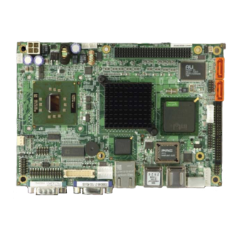
intel celeron m/pentium m based epic nano motherboard with lvds, vga, sata, ide, usb 2.0, pc-104 expansion slot and ethernet
Brand:
IEI Technology
| Category:
Motherboard
| Size: 12.3 MB
Table of Contents
Packing List
6
Table of Contents
7
1 Introduction
21
Overview
22
NANO-8522 Features
22
Nano-8522 Overview
23
NANO-8522 Overview Photo
23
Figure 1-2: NANO-8522 Overview
23
NANO-8522 Peripheral Connectors and Jumpers
24
Figure 1-3: NANO-8522 Overview
24
Technical Specifications
25
Table 1-1: Technical Specifications
27
2 Detailed Specifications
28
Overview
29
Dimensions
29
Board Dimensions
29
Figure 2-1: NANO-8522 Dimensions (MM)
29
External Interface Panel Dimensions
30
Figure 2-2: External Interface Panel Dimensions (MM)
30
Data Flow
31
Figure 2-3: Data Flow Block Diagram
31
Compatible Processors
32
CPU Overview
32
Supported Intel® Pentium® M Processors
32
Figure 1-1: NANO-8522
32
Figure 2-4: CPU
32
Table 2-1: Supported Intel® Pentium® M Processors
32
Supported Intel® Celeron® M Processors
33
Intel 852Gm Graphics Memory Controller Hub
33
Figure 2-5: Intel® 852GM
33
Table 2-2: Supported Intel® Celeron M Processors
33
Intel 852GM Memory Support
34
Intel ® 852GM Display and Graphics Support
35
Analog CRT
35
Figure 2-6: 200-Pin DDR SO-DIMM Socket
35
Figure 2-7: Display and Graphics Support
35
LVDS Display Support
36
Intel 852GM Internal Graphics Controller
36
Intel ® 82801Db I/O Controller Hub (Ich4)
38
Figure 2-8: Intel® ICH4
38
AC'97 Controller
39
Figure 2-9: IDE Interface
39
IDE Interface
39
Table 2-3: Supported HDD Specifications
39
Figure 2-10:Realtek ALC655 Codec
40
USB Controller
41
Figure 2-11: USB
42
PCI Interface
42
LPC Interface
43
Lpc Bus Components
43
LPC Bus Overview
43
Fintek F81216DG LPC Serial Port Chipset
44
BIOS Chipset
44
Figure 2-12: Serial Port Chipset
44
Super I/O Chipset
45
Figure 2-13: BIOS Chipset
45
Figure 2-14: Super I/O Chipset
46
Infrared
46
LPC Interface
46
Figure 2-15: Infrared
47
Hardware Monitor Functions
47
Parallel Port
47
Figure 2-16: Parallel Port
48
Keyboard and Mouse Controller
48
DIO Ports
49
Fan Speed and Fan Control
49
Figure 2-17: Keyboard and Mouse
49
Figure 2-18: Intel® 852GM
49
Pci Bus Components
50
Intel® 82551ER PCI Ethernet Controller
50
Figure 2-19: PCI Interface
50
Intel® 82541PI PCI Gigabit Ethernet Controller
51
Figure 2-20: Ethernet Controller
51
VIA® VT6421 SATA Drive Controller
52
Figure 2-21: SATA Drive Controller
52
Expansion Port
53
Environmental and Power Specifications
53
System Monitoring
53
Figure 2-22: PCI-104 Expansion Port
53
Operating Temperature and Temperature Control
54
Power Consumption
54
Embedded Systems
54
NANO-8522 Embedded Systems
54
Table 2-4: Power Consumption
54
Table 2-5: NANO-8522 Embedded Systems
55
3 Unpacking
56
Anti-Static Precautions
57
Unpacking
57
Unpacking Precautions
57
Unpacking Checklist
58
Package Contents
58
Table 3-1: Package List Contents
59
Optional Components
60
Table 3-2: Optional Components
60
4 Connector Pinouts
61
Peripheral Interface Connectors
62
NANO-8522 Layout
62
Figure 4-1: Connector and Jumper Locations
62
Peripheral Interface Connectors
63
Figure 4-2: Solder Side Connector and Jumper Locations
63
External Peripheral Interface Panel Connectors
64
Table 4-1: Peripheral Interface Connectors
64
Internal Peripheral Connectors
65
ATX Power Supply Connector
65
Figure 4-3: +12 V ATX Power Connector Location
65
Table 4-2: External Peripheral Interface Panel Connectors
65
ATX Power Supply Enable Connector
66
Figure 4-4: ATX Power Supply Enable Connector Location
66
Table 4-3: +12 V ATX Power Connector Pinouts
66
Table 4-4: ATX Power Supply Enable Connector Pinouts
66
Audio Connector (10-Pin)
67
Figure 4-5: Audio Connector Pinouts (10-Pin)
67
Table 4-5: Audio Connector Pinouts (10-Pin)
67
Backlight Inverter Connector
68
Battery Connector
68
Figure 4-6: Panel Backlight Connector Pinout Locations
68
Table 4-6: Panel Backlight Connector Pinouts
68
Compactflash® Socket
69
Figure 4-7: Battery Connector Location
69
Table 4-7: Battery Connector Pinouts
69
Figure 4-8: CF Card Socket Location
70
Digital Input/Output (DIO) Connector
71
Table 4-8: CF Card Socket Pinouts
71
Fan Connectors
72
Figure 4-9: DIO Connector Locations
72
Table 4-9: DIO Connector Pinouts
72
IDE Connector(44-Pin)
73
Figure 4-10: Fan Connectors Locations
73
Table 4-10: Fan Connectors Pinouts
73
Figure 4-11: Secondary IDE Device Connector Locations
74
Infrared Interface Connector (5-Pin)
75
Table 4-11: Secondary IDE Connector Pinouts
75
Keyboard/Mouse Connector
76
Figure 4-12: Infrared Connector Pinout Locations
76
Table 4-12: Infrared Connector Pinouts
76
LED Connector
77
Figure 4-13: Keyboard/Mouse Connector Location
77
Table 4-13: Keyboard/Mouse Connector Pinouts
77
LVDS LCD Connector
78
Figure 4-14: LED Connector Locations
78
Table 4-14: LED Connector Pinouts
78
Figure 4-15: LVDS LCD Connector Pinout Locations
79
Parallel Port Connector
80
Table 4-15: LVDS LCD Port Connector Pinouts
80
Figure 4-16: Parallel Port Connector Location
81
Slot
82
Table 4-16: Parallel Port Connector Pinouts
82
Figure 4-17: PCI-104 Slot Location
83
Table 4-17: PCI-104 Slot Connector Pinouts
84
Power Button Connector
85
Reset Button Connector
85
Figure 4-18: Power Button Connector Location
85
Table 4-18: Power Button Connector Pinouts
85
SATA Drive Connectors
86
Figure 4-19: Reset Button Connector Locations
86
Table 4-19: Reset Button Connector Pinouts
86
SATA Drive Power Connector
87
Figure 4-20: SATA Drive Connector Locations
87
Table 4-20: SATA Drive Connector Pinouts
87
Serial Port Connector (COM2)(RS-232, RS-422 or RS-485)
88
Figure 4-21: SATA Power Connector
88
Table 4-21: SATA Power Connector
88
Serial Port Connector (COM3, COM4)
89
Figure 4-22: RS-232/422/485 Serial Port Connector Location
89
Table 4-22: RS-232/RS-485 Serial Port Connector Pinouts
89
USB Connector (Internal)
90
Figure 4-23: Serial Port Connector Pinout Locations
90
Table 4-23: Serial Connector Pinouts
90
Figure 4-24: USB Connector Pinout Locations
91
Table 4-24: USB Port Connector Pinouts
91
External Peripheral Interface Connectors
92
Keyboard/Mouse Connector
92
Figure 4-25: NANO-8522 External Peripheral Connector Panel
92
Ethernet Connector
93
Figure 4-26: PS/2 Pinout and Configuration
93
Table 4-25: Keyboard Connector Pinouts
93
Serial Port Connectors
94
Figure 4-27: Ethernet Connector
94
Table 4-26: Ethernet Connector Pinouts
94
Table 4-27: Ethernet Connector Leds
94
USB Connectors
95
Figure 4-28: COM1 Pinout Locations
95
Table 4-28: RS-232 Serial Port (COM 1) Pinouts
95
Table 4-29: USB Connector Pinouts
95
VGA Connector
96
On-Board Jumpers
96
Figure 4-29: VGA Connector
96
Table 4-30: VGA Connector Pinouts
96
5 Installation
97
Anti-Static Precautions
98
Installation Considerations
98
Installation Notices
99
Installation Checklist
99
Cpu, Cpu Cooling Kit and DIMM Installation
101
Socket 479 CPU Installation
101
Figure 5-1: Make Sure the CPU Socket Retention Screw Is Unlocked
102
Socket 479 Cooling Kit Installation
103
Figure 5-2: Lock the CPU Socket Retention Screw
103
Figure 5-3: IEI Cooling Kits
103
Figure 5-4: Cooling Kit Support Bracket
104
Figure 5-5: Securing the Cooling Kit
105
Figure 5-6: Connect the Cooling Fan Cable
105
SO-DIMM Installation
106
Figure 5-7: SO-DIMM Installation
106
CF Card Installation
107
Jumper Settings
108
Figure 5-8: CF Card Installation
108
Figure 5-9: Jumper Locations
108
CF Card Setup
109
Table 5-1: Jumpers
109
Table 5-2: CF Card Setup Jumper Settings
109
Clear CMOS Jumper
110
Figure 5-10: CF Card Setup Jumper Location
110
COM 2 Function Select Jumper
111
Figure 5-11: Clear CMOS Jumper
111
Table 5-3: Clear CMOS Jumper Settings
111
Figure 5-12: COM 2 Function Select Jumper Location
112
LVDS Voltage Selection
112
Table 5-4: COM 2 Function Select Jumper Settings
112
Figure 5-13: LVDS Voltage Selection Jumper Pinout Locations
113
Serial IRQ Selector
113
Table 5-5: LVDS Voltage Selection Jumper Settings
113
Table 5-6: PCI-104 Voltage Setup Jumper Settings
113
Chassis Installation
114
Airflow
114
Figure 5-14: PCI-104 Voltage Setup Jumper Pinout Locations
114
Motherboard Installation
115
Internal Peripheral Device Connections
115
Peripheral Device Cables
115
Audio Kit Installation
115
Table 5-7: IEI Provided Cables
115
IDE Cable Connection
116
Figure 5-15: Audio Kit Cable Connection
116
LVDS LCD Installation
117
Figure 5-16: IDE Cable Connection
117
Figure 5-17: LVDS Connector
118
Single RS-232 Cable (W/O Bracket)
119
Figure 5-18: Backlight Inverter Connection
119
SATA Drive Connection
120
Figure 5-19: Single RS-232 Cable Installation
120
Figure 5-20: SATA Drive Cable Connection
121
External Peripheral Interface Connection
122
PS/2 Y-Cable Connection
122
Figure 5-21: SATA Power Drive Connection
122
Figure 5-22: PS/2 Keyboard/Mouse Connector
123
Ethernet Connection
124
Serial Device Connection
124
Figure 5-23: RJ-45 Connector
124
USB Connection (Dual Connector)
125
Figure 5-24: Serial Device Connector
125
VGA Monitor Connection
126
Figure 5-25: USB Connector
126
Figure 5-26: VGA Connector
127
6 Bios Setup
128
Introduction
129
Starting Setup
129
Using Setup
129
Getting Help
130
Unable to Reboot after Configuration Changes
130
BIOS Menu Bar
130
Table 6-1: BIOS Navigation Keys
130
Main
131
BIOS Menu 1: Main
131
Advanced
132
BIOS Menu 2: Advanced
133
CPU Configuration
134
BIOS Menu 3: CPU Configuration
134
IDE Configuration
135
BIOS Menu 4: IDE Configuration
135
IDE Master, IDE Slave
137
BIOS Menu 5: IDE Master and IDE Slave Configuration
137
Super IO Configuration
142
BIOS Menu 6: Super IO Configuration
142
Hardware Health Configuration
146
BIOS Menu 7: Hardware Health Configuration
146
Remote Access Configuration
147
BIOS Menu 8: Remote Access Configuration
147
USB Configuration
150
BIOS Menu 9: USB Configuration
150
Pci/Pnp
151
BIOS Menu 10: Pci/Pnp Configuration
152
Boot
154
BIOS Menu 11: Boot
154
Boot Settings Configuration
155
BIOS Menu 12: Boot Settings Configuration
155
Boot Device Priority
157
Removable Drives
157
BIOS Menu 13: Boot Device Priority Settings
157
BIOS Menu 14: Removable Drives
158
Security
159
BIOS Menu 15: Security
159
Chipset
160
BIOS Menu 16: Chipset
161
Northbridge Configuration
162
BIOS Menu 17:Northbridge Chipset Configuration
162
Southbridge Chipset Configuration
165
BIOS Menu 18: Southbridge Chipset Configuration
165
Power
166
BIOS Menu 19:Power
166
Exit
169
BIOS Menu 20:Exit
169
7 Raid Setup
171
Via® Raid Utility
172
Accessing the Raid Utility
172
Figure 7-1: RAID Utility
172
Creating Araid Array
173
Figure 7-2: RAID Setup Main Screen
173
Figure 7-3: Create Array
173
Automatic Setup
174
Figure 7-4: RAID Type
174
Figure 7-5: Automatic Setup
174
Figure 7-6: Confirm Data Deletion
175
Figure 7-7: RAID Array Setup Complete
175
Figure 7-8: Select Drives
176
Figure 7-9: Select First Drive
176
Manual Setup
176
Figure 7-10: Select Second Drive
177
Figure 7-11: Disk Drives Selected
177
Figure 7-12: Stripe Size
178
Figure 7-13: Select Stripe Size
178
Figure 7-14: Start RAID Creation
179
Figure 7-15: Confirm RAID Creation
179
Delete Araid Array
180
Figure 7-16: RAID Array Created
180
Figure 7-17: Delete RAID Array
180
Figure 7-18: Select Array to Delete
181
Figure 7-19: Confirm Array Deletion
181
Selecting a Boot Array
182
Figure 7-20: Array Deleted
182
Figure 7-21: Select Boot Array
182
Viewing Disk Drive Serial Numbers
183
Figure 7-22: Select Boot Array
183
Figure 7-23: Set Array as Boot Array
183
Figure 7-24: Serial Number View
184
Figure 7-25: Serial Number
184
Exiting the Raid Utility
185
Figure 7-26: Exit RAID Utility
185
8 Software Drivers
186
Available Software Drivers
187
Driver CD Auto-Run
187
Figure 8-1: Introduction Screen
188
Figure 8-2: Available Drivers
188
Chipset Driver Installation
189
Figure 8-3: Chipset Driver Icon
189
Figure 8-4: Installshield Wizard Preparation Screen
190
Figure 8-5: Welcome Screen
190
Figure 8-6: License Agreement
191
Figure 8-7: Readme Information
191
Realtek Audio Driver Installation
192
Figure 8-8: Restart the Computer
192
Figure 8-9: ALC655 Directory Icon
193
Figure 8-10: Audio Driver Operating System
194
Figure 8-11: Audio Driver Setup Icon
194
Figure 8-12: Audio Driver Install Shield Wizard Starting
195
Figure 8-13: Audio Driver Setup Preparation
195
Figure 8-14: Audio Driver Welcome Screen
196
Figure 8-15: Audio Driver Software Configuration
196
Figure 8-16: Audio Driver Digital Signal
197
Figure 8-17: Audio Driver Installation Begins
197
Intel Graphics Media Accelerator Driver
198
Figure 8-18: Audio Driver Installation Complete
198
Figure 8-19: Operating Systems
198
Figure 8-20: VGA Setup Icon
199
Figure 8-21: GMA Driver Installation Welcome Screen
199
Figure 8-22: GMA Driver License Agreement
200
Figure 8-23: GMA Driver Installing Notice
200
Intel ® Network Adapter Installation
201
Figure 8-24: GMA Driver Installation Complete
201
Figure 8-25: Select the Driver Folder
201
Figure 8-26: Select the Driver
202
Figure 8-27: Network Adapter License Agreement
202
Figure 8-28: Location to Save Files
203
Figure 8-29: Installshield Wizard Extracting Files
203
Figure 8-30: Overwrite Protection
204
Figure 8-31: File Extraction Continues
204
Intel ® Usb 2.0 Installation
205
Figure 8-32: Intel® Pro Network Connections
205
Figure 8-33: Intel® Pro Network Connections Driver Installation Notice
205
Figure 8-34: USB2.0 Window
206
Figure 8-35: USB2.0 os Options
206
Figure 8-36: Windows XP USB 2.0 Program Icon
207
Figure 8-37: USB 2.0 Installshield Wizard
207
Figure 8-38: USB 2.0 Installshield Wizard Continues
208
Figure 8-39: USB 2.0 Installshield Wizard Welcome Screen
208
Figure 8-40: USB 2.0 License Agreement
209
Figure 8-41: USB 2.0 Driver Installed
209
Sata/Raid Driver
210
Figure 8-42: USB 2.0 Driver Installation Complete
210
Figure 8-43: Locate the Setup Program Icon
211
Figure 8-44: Preparing Setup Screen
211
Figure 8-45: Install Wizard Welcome Screen
212
Figure 8-46: Software License Agreement
212
Figure 8-47: Select Driver Packages
213
Figure 8-48: Review Installation Items
213
Figure 8-49: Installation Status
214
Figure 8-50: Installshield Wizard Complete Screen
214
ABIOS Options
215
B Terminology
218
C Digital I/O Interface
222
Introduction
223
Dio Connector Pinouts
223
Assembly Language Samples
224
Enable the DIO Input Function
224
Enable the DIO Output Function
224
D Watchdog Timer
225
E Address Mapping
228
Direct Memory Access (Dma)
229
Emory a Ccess (Dma)
229
Input/Output (IO)
230
Interrupt Request (Irq)
232
R Equest (Irq)
232
Memory
233
F Hazardous Materials Disclosure
234
Hazardous Materials Disclosure Table for IPB Products Certified as Rohs Compliant under 2002/95/EC Without Mercury
235
GRAID Levels
238
Raid 0
240
Figure G-1: RAID 0
240
Raid 1
241
Figure G-2: RAID 1
241
Jbod
242
Advertisement
IEI Technology NANO-8522 User Manual (204 pages)
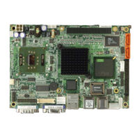
EPIC SBC With Intel Celeron M 1GHz Zero Cache Processor On Board With VGA/LVDS, Lan, Sata And Audio
Brand:
IEI Technology
| Category:
Single board computers
| Size: 3.89 MB
Table of Contents
Table of Contents
3
1 Introduction
15
NANO-8522Board Overview
16
NANO-8522 Board Benefits
16
NANO-8522 Board Features
16
NANO-8522 Board Variations
16
Table 1-1: NANO-8522 Board Variations
16
Nano-8522 Board Overview
18
Figure 1-1: NANO-8522 Board Overview (Top View)
18
Figure 1-2: NANO-8522 Board Overview (Bottom View)
18
NANO-8522 Board Connectors
19
Technical Specifications
20
Table 1-2: Technical Specifications
21
2 Detailed Specifications
23
Cpu Support
24
Intel ® Celeron ® M
24
Intel ® Pentium ® M
24
Table-2-1: Supported Cpus
24
Intel® 852GM Northbridge Chipset
25
Intel® ICH4 Southbridge Chipset
25
Northbridge and Southbridge Chipsets
25
Onboard Chipsets
25
Data Flow
27
Figure 2-1: Data Flow Block Diagram
27
Graphics Support
28
Memory Support
29
Pci Bus Interface Support
29
10/100/1000 Base-T Internet
30
Ide Device Support
30
Bios
31
Operating Temperature and Temperature Control
31
Real Time Clock
31
Sata Drive Support
31
System Monitoring
31
Usb Interfaces
31
Audio Codec
32
Power Consumption
33
Package Contents
34
Packaged Contents and Optional Accessory Items
34
Table 2-2: Power Consumption
34
Table 2-3: Power Consumption
34
3 Connectors and Jumpers
37
Peripheral Interface Connectors
38
Figure 3-1: Connector and Jumper Locations (Top Side)
38
NANO-8522 Board Layout
38
Figure 3-2: Connector and Jumper Locations (Solder Side)
39
Peripheral Interface Connectors
39
Rear Panel Connectors
40
Table 3-1: Peripheral Interface Connectors
40
Onboard Jumpers
41
Internal Peripheral Connectors
41
4-Bit GPIO Connector
41
Table 3-2: Peripheral Interface Connectors
41
Table 3-3: Onboard Jumpers
41
ATX Power Button Connector
42
Figure 3-3: 4-Bit GPIO Connector Location
42
Table 3-4: 4-Bit GPIO Connector Pinouts
42
ATX Power Connector
43
Figure 3-4: Power Button Connector Location
43
Table 3-5: Power Button Connector Pinouts
43
Audio Connector
44
Figure 3-5: Power Connector Location
44
Table 3-6: Power Connector Pinouts
44
Battery Connector
45
Figure 3-6: Audio Connector Location
45
Table 3-7: Audio Connector Pinouts
45
Figure 3-7: Battery Connector Location
46
Power Connector
46
Table 3-8: 12V Power Connector Pinouts
46
Compact Flash Type 2 Socket
47
Figure 3-8: 12V Power Connector Location
47
Figure 3-9: CFII Socket Location (Solder Side)
48
Table 3-9: CFII Socket Pinouts
48
DDR SODIMM Socket
49
Fan Connector
49
Figure 3-10: SODIMM Socket Location (Solder Side)
49
Figure 3-11: Fan Connector Location
50
IDE Interface Connector
50
Table 3-10: Fan Connector Pinouts
50
Table 3-11: IDE Connector Pinouts
51
Figure 3-12: IDE Connector Location
52
Inverter Connector
52
Table 3-12: Inverter Connector Pinouts
52
Figure 3-13: Inverter Connector Location
53
IR Interface Connector
53
Table 3-13: IR Interface Connector Pinouts
53
Figure 3-14: IR Interface Connector Location
54
Keyboard/Mouse Connector
54
Table 3-14: Keyboard/Mouse Connector Pinouts
54
Figure 3-15: Keyboard/Mouse Connector Location
55
LED Connector
55
Table 3-15: LED Connector Pinouts
55
Figure 3-16: LED Connector Location
56
LVDS Connector
56
Figure 3-17: LVDS Connector
57
Parallel Port Connector
57
Table 3-16: LVDS Connector Pinouts
57
Figure 3-18: Parallel Port Connector Location
58
Table 3-17: Parallel Port Connector Pinouts
58
PC/104+ Connector
59
Figure 3-19: PC/104+ Connector Location
60
Reset Connector
60
Table 3-18: PC104+ Connector Pinouts
60
Figure 3-20: Reset Connector Location
61
SATA Connectors
61
Table 3-19: Reset Connector Pinouts
61
Figure 3-21: SATA Connector Location
62
Serial Port2 Connector
62
Table 3-20: SATA Connector Pinouts
62
Figure 3-22: COM2 Connector Location
63
Serial Port3 Connector
63
Table 3-21: COM2 Connector Pinouts
63
Figure 3-23: COM3 Connector Location
64
Serial Port4 Connector
64
Table 3-22: COM3 Connector Pinouts
64
Figure 3-24: COM4 Connector Location
65
Table 3-23: COM4 Connector Pinouts
65
USB Connector
65
External (Rear Panel) Connectors
66
Figure 3-25: USB Connector Location
66
Table 3-24: USB Connector Pinouts
66
Ethernet Connector
67
Figure 3-26: NANO-8522 Board Rear Panel
67
Table 3-25: RJ-45 Ethernet Connector Pinouts
67
Figure 3-27: RJ-45 Ethernet Connector
68
Keyboard/Mouse Connector
68
Serial Port Connectors
68
Table 3-26: RJ-45 Ethernet Connector Leds
68
Table 3-27: Serial Port Pinouts
69
Table 3-28: USB1 Connector Pinouts
69
Table 3-29: USB2 Connector Pinouts
69
USB Connectors
69
VGA Connector
69
Onboard Jumpers
70
Figure 3-28 Jumper
70
Table 3-30: VGA Connector Pinouts
70
CF Card Setup
71
Figure 3-29: Jumper Locations
71
Clear CMOS Jumper
72
Table 3-31: JP1 Jumper Settings
72
Table 3-32: JP4 Jumper Settings
72
COM2 Selector
73
LCD Voltage Selector
73
Table 3-33: JP2 Jumper Settings
73
Table 3-34: JP6 Jumper Settings
73
PC/104+ Selector
74
Table 3-35: JP5 Jumper Settings
74
4 Installation and Configuration
75
Installation Considerations
76
Installation Notices
76
Unpacking
77
Checklist
77
Unpacking Precautions
77
Nano-8522 Board Installation
78
Preinstalled Components
78
Components to Install
79
CPU Installation
79
Figure 4-1: Make Sure the CPU Socket Retention Screw Is Unlocked
80
Cooling Kit (CF-479B-RS) Installation
81
Figure 4-2: Lock the CPU Socket Retention Screw
81
Figure 4-3: IEI CF-479B-RS Cooling Kit
81
Figure 4-4: Securing the Cooling Kit
82
DIMM Module Installation
83
Figure 4-5: Connect the Cooling Fan Cable
83
Purchasing the Memory Module
83
IDE Disk Drive Connector (IDE1)
84
Peripheral Device Connection
84
Table 4-1: IEI Provided Cables
84
Keyboard/Mouse Connection
85
Chassis Installation
85
Rear Panel Connectors
85
LCD Panel Connection
85
Ethernet Connection
86
Keyboard and Mouse Connection
86
USB Connection
86
5 Ami Bios Setup
87
Introduction
88
Starting Setup
88
Using Setup
88
BIOS Menu Bar
89
Getting Help
89
Table 5-1: BIOS Navigation Keys
89
Unable to Reboot after Configuration Changes
89
Main
90
System Overview
90
Advanced
91
System Date [XX/XX/XX]
91
System Time [XX:XX:XX]
91
CPU Configuration
92
Hyper Threading Technology [Enabled]
93
IDE Configuration
94
Onboard PCI IDE Controller [Both]
94
Hard Disk Write Protect [Disabled]
95
Onboard PCI IDE Mode [Legacy Mode]
95
IDE Detect Time out (Sec) [35]
95
ATA (PI) 80Pin Cable Detection [Host & Device]
96
IDE Master and IDE Slave
96
IDE Master, IDE Slave
97
Auto-Detected Drive Parameters
98
Type [Auto]
98
Zip
99
Block (Multi Sector Transfer) [Auto]
99
Lba/Large Mode [Auto]
99
Auto]
100
DMA Mode [Auto]
100
PIO Mode [Auto]
100
32Bit Data Transfer [Disabled]
101
Floppy Configuration
101
Super IO Configuration
102
Floppy a [Disabled]
102
Floppy B [Disabled]
102
On Board Floppy Controller [Enabled]
103
Serial Port1 Address [3F8/IRQ4]
103
Serial Port2 Address [2F8/IRQ3]
104
Serial Port2 Mode [Normal]
104
Parallel Port Address [378]
104
Parallel Port Mode [Normal]
105
Parallel Port IRQ [IRQ7]
106
Serial Port3 Address [3E8]
106
Serial Port3 IRQ [11]
106
Serial Port4 Address [2E8]
106
Hardware Health Configuration
107
Serial Port4 IRQ [10]
107
ACPI Configuration
109
General ACPI Configuration
109
Suspend Mode [Auto]
110
Advanced ACPI Configuration
111
Repost Video on S3 Resume [No]
111
ACPI 2.0 Features [No]
112
ACPI APIC Support [Enabled]
112
AMI OEMB Table [Enabled]
112
Chipset ACPI Configuration
113
Headless Mode [Disabled]
113
MPS Configuration
114
APIC ACPI SCI IRQ [Disabled]
114
USB Device Wakeup from S3/S4 [Disabled]
114
MPS Revision [1.4]
115
Smbios Configuration
115
Smbios Smi Support [Enabled]
116
USB Configuration
116
USB Configuration
117
USB Devices Enabled
117
USB Function [6 USB Ports]
117
Legacy USB Support [Enabled]
118
USB 2.0 Controller [Enabled]
118
USB2.0 Controller Mode [Hispeed]
118
Pci/Pnp
119
BIOS EHCI Handoff [Enable]
119
USB Mass Storage Device Configuration
119
Clear NVRAM [No]
120
Plug & Play O/S [No]
120
PCI Latency Timer [64]
121
Allocate IRQ to PCI VGA [Yes]
121
Palette Snooping [Disabled]
121
Offboard PCI/ISA IDE Card [Auto]
122
PCI IDE Busmaster [Disabled]
122
IRQ# [Available]
123
Boot
124
DMA Channel# [Available]
124
Reserved Memory Size [Disabled]
124
Boot Settings Configuration
125
Quick Boot [Enabled]
126
Quiet Boot [Disabled]
126
Addon ROM Display Mode [Force BIOS]
127
Bootup Num-Lock [On]
127
PS/2 Mouse Support [Auto]
127
Wait for 'F1' if Error [Enabled]
128
Hit 'DEL' Message Display [Enable]
128
Interrupt 19 Capture [Disabled]
128
Security
129
Change Supervisor Password
129
Chipset
130
Change User Password
130
Clear User Password
130
Boot Sector Virus Protection [Disabled]
130
Northbridge Configuration
131
DRAM Frequency [Auto]
132
Configure DRAM Timing by SPD [Enabled]
133
Memory Hole [Disabled]
133
Graphics Aperture Size [64MB]
134
Init. Graphic Adapter Priority [Internal VGA]
134
Internal Graphics Mode Select [Enable, 8MB]
134
Boot Display Device [Auto]
134
Flat Panel Type [640X480 18Bit LVDS]
135
Southbridge Configuration
136
Local Flat Panel Scaling [Auto]
136
Onboard AC97 Audio DEVICE
137
Restore on AC Power Loss [Last State]
137
Power Key
138
Power Management/Apm [Enabled]
138
Video Power down Mode [Suspend]
139
Hard Disk Power down Mode [Suspend]
139
Standby Time out [Disabled]
139
Suspend Time out [Disabled]
140
Throttle Slow Clock Ratio [50%]
140
FDC/LPT/COM Ports [MONITOR]
141
Keyboard & PS/2 Mouse [MONITOR]
141
Primary Master IDE [MONITOR]
142
Primary Slave IDE [MONITOR]
142
Secondary Master IDE [MONITOR]
142
Secondary Slave IDE [MONITOR]
143
System Thermal [Disabled]
143
Power Button Mode [On/Off]
143
Resume on Ring [Disabled]
144
Resume on Lan [Disabled]
144
Resume on PME# [Disabled]
144
Resume on RTC Alarm [Disabled]
144
Exit
145
RTC Alarm Date (Days)
145
System Time
145
Save Changes and Exit
146
Discard Changes
146
Discard Changes and Exit
146
Load Optimal Defaults
146
Load Failsafe Defaults
147
6 Software Drivers
149
Available Software Drivers
150
Chipset Driver Installation
150
Figure 6-1: Installshield Wizard Preparation Screen
151
Figure 6-2: Welcome Screen
151
Figure 6-3: License Agreement
152
Figure 6-4: Readme Information
152
Realtek Audio Driver Installation
153
Figure 6-5: Restart the Computer
153
Figure 6-6: Audio Driver Install Shield Wizard Starting
154
Figure 6-7: Audio Driver Setup Preparation
154
Figure 6-8: Audio Driver Welcome Screen
155
Figure 6-9: Audio Driver Software Configuration
155
Figure 6-10: Audio Driver Digital Signal
156
Figure 6-11: Audio Driver Installation Begins
157
Intel Graphics Media Accelerator Driver
158
Figure 6-12: Audio Driver Installation Complete
158
Figure 6-13: GMA Driver Installation Welcome Screen
159
Figure 6-14: GMA Driver License Agreement
160
Figure 6-15: GMA Driver Installing Notice
160
Lan Driver Installation
161
Figure 6-16: GMA Driver Installation Complete
161
Figure 6-17: LAN License Agreement
162
Figure 6-18: Select the Driver Directory
162
Figure 6-19: LAN Driver Configuration
163
Sata - al Iraid Driver Installation
164
Installation Steps During Windows XP Installation
164
Installation Steps under Existing Windows XP
165
Bios Configuration Options
167
A.1 BIOS Configuration Options
168
Bios Configuration Options
168
Bwatchdog Timer
173
AH - 6FH Sub-Function
174
Caddress Mapping
177
Io Address Map
178
St Mb Memory Address Map
178
Irq Mapping Table
179
Dma Channel Assignments
179
Dexternal Ac'97 Audio Codec
181
Introduction
182
Accessing the AC '97 CODEC
182
Driver Installation
182
Sound Effect Configuration
183
Accessing the Sound Effects Manager
183
Figure 6-20: Sound Effect Manager con
183
Figure 6-21: Sound Effect Manager Icon [Task Bar]
183
Figure 6-22: Sound Effect Manager Icon [Control Panel]
184
Figure 6-23: Sound Effects Manager (ALC655)
184
Sound Effect Manager Configuration Options
185
Eali® Raid for Sata
187
Introduction
188
Features and Benefits
189
Accessing the al Iraid Utility
189
Raid Bios Setup Utility
190
Raid Options
191
Create RAID0 Striping for Performance
191
Create RAID1 Mirroring for Reliability
192
Create JBOD for Integrated Capacity
194
Stripe Size
195
Delete All RAID Setting & Partition
196
Delete RAID Setting & Partition
196
Rebuild RAID Array
197
Select Boot Drive
197
Fdigital I/O Port Programming Guide
199
IEI Technology NANO-8522 Quick Installation Manual (10 pages)
EPIC Intel Pentium M/Celeron M CPU with VGA/LVDS, SATA, LAN and Audio
Brand:
IEI Technology
| Category:
Motherboard
| Size: 0.3 MB
Table of Contents
Quick Installation Guide
1
Specifications
2
Ordering Information
3
Jumpers Setting and Connectors
3
Board Layout: Jumper and Connector Locations
9
Advertisement
IEI Technology NANO-8522 Quick Installation Manual (9 pages)
single board computer
Brand:
IEI Technology
| Category:
Desktop
| Size: 0.13 MB
Table of Contents
Quick Installation Guide
1
Ordering Information
3
Jumpers Setting and Connectors
3
Board Layout: Jumper and Connector Locations
9
Advertisement
Related Products
IEI Technology NANO-PV-D510A
IEI Technology NANO-HM551
IEI Technology NANO-CV-N26001
IEI Technology NANO-945GSE2
IEI Technology NANO-LX2
IEI Technology NANO-PV-D4252-R10
IEI Technology NANO-HM650-R11
IEI Technology NANO-CV-D25501-R10
IEI Technology NANO-QM871-i1-i5
IEI Technology NANO-QM871-i1-i3
IEI Technology Categories
Motherboard
Touch Panel
Computer Hardware
Single board computers
Desktop
More IEI Technology Manuals
Login
Sign In
OR
Sign in with Facebook
Sign in with Google
Upload manual
Upload from disk
Upload from URL