IEI Technology NANO-8522 Quick Installation Manual
Single board computer
Hide thumbs
Also See for NANO-8522:
- User manual (249 pages) ,
- Quick installation manual (10 pages) ,
- User manual (204 pages)
Advertisement
EPIC Intel® Pentium® M/Celeron® M CPU with
Quick Installation Guide
Package Contents
NANO-8522 package includes the following items:
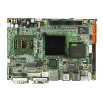
1 x NANO-8522 Single Board Computer
1 x IDE flat cable 44p/44p
1 x KB/MS Y cable
1 x Audio cable
2 x SATA cable
1 x SATA Power cable
1 x Power cable
2 x RS-232 cable
1 x Mini Jumper Pack
1 x Utility CD
1 x QIG (Quick Installation Guide)
VGA/LVDS, SATA, LAN and Audio
NANO-8522
Version 1.3
Jun. 23, 2008
©2006 Copyright by IEI Technology corp.
All rights reserved.
1
Advertisement
Table of Contents

Related Manuals for IEI Technology NANO-8522


Summary of Contents for IEI Technology NANO-8522
-
Page 1: Quick Installation Guide
NANO-8522 Quick Installation Guide Version 1.3 Jun. 23, 2008 Package Contents NANO-8522 package includes the following items: 1 x NANO-8522 Single Board Computer 1 x IDE flat cable 44p/44p 1 x KB/MS Y cable 1 x Audio cable 2 x SATA cable... - Page 2 Specifications CPU: Socket 479 Intel® Pentium® M, Celeron® M processor with a 400MHz FSB On board Intel® Celeron® M 600MHz 512KB or 1GHz zero cache processor System Chipset: Intel 852GM+ICH4 BIOS: AMI BIOS System memory: 1x 200-Pin SO-DIMM DDR 266MHz up to 1GB Ethernet Intel®...
-
Page 3: Ordering Information
Power Consumption: 12V@0.96A (ULV Intel® Celeron® M 800MHz zero cache with DDR 266 MHZ, 256 MB RAM) 12V@1.99A (Pentium M 1.7GHz/L2-2M withDDR266MHz, 512MB RAM) Humidity: Operation: 5% ~ 95%, non-condensing Temperature: 0 ~ 60°C(32 ~ 140°F) Dimension: 165 mm x 115 mm Weight: GW: 1100g;... - Page 4 JP4: Clear CMOS Setup JP5: PCI-104 SERIRQ net to (Reserve Function) CN3 pin B1 Selector DESCRIPTION DESCRIPTION Normal Operation Open Disconnect Clear CMOS Setup Connect JP6: LCD Voltage Selector BT1: Battery Connector (LVDS1 pin27~30) DESCRIPTION DESCRIPTION BAT+ LCDVCC = +3.3V LCDVCC = +5V AUDIO1: Audio connector (Box-header 5x2 2.0mm) Description...
- Page 5 CN5: LED Connector CN7: 2.5" SATA HDD power connector Description DESCRIPTION Power LED+ Power LED- HDD LED+ HDD LED- CN6: Compact Flash Connector (Secondary IDE) Description Description GROUND VCC-IN CHECK1 DATA3 DATA11 DATA4 DATA12 DATA5 DATA13 DATA6 DATA14 DATA7 DATA15 HDC_CS0# HDC_CS1 GROUND...
- Page 6 COM2: Serial Port2 connector (Pin-header 7x2 2.0mm) Description Description DCD# DSR# RTS# CTS# DTR# TxD485+ TxD485- RxD485+ RxD485- COM3: Serial Port3 Connector (Pin-header 5x2 2.0mm) Description Description DCD# DSR# RTS# CTS# DTR# COM4: Serial Port4 Connector (Pin-header 5x2 2.0mm) Description Description DCD# DSR#...
- Page 7 LPT1: Parallel Port Connector Description Description STROBE# AUTO FORM FEED # DATA 0 ERROR# DATA 1 INITIALIZE DATA 2 PRINTER SELECT LN# DATA 3 GROUND DATA 4 GROUND DATA 5 GROUND DATA 6 GROUND DATA 7 GROUND ACKNOWLEDGE GROUND BUSY GROUND PAPER EMPTY GROUND...
- Page 8 LVDS1: LCD Interface Connector – support LVDS 18 BIT 2 CH Description Description AY0- AY0+ AY1- AY1+ AY2- AY2+ AYCLK- AYCLK+ AY3- AY3+ BY0- BY0+ BY1- BY1+ BY2- BY2+ BYCLK- BYCLK+ BY3- BY3+ LCDVCC LCDVCC LCDVCC LCDVCC USB1, 2: External USB Connector PIN NO.
-
Page 9: Board Layout: Jumper And Connector Locations
Board Layout: Jumper and Connector Locations...
Need help?
Do you have a question about the NANO-8522 and is the answer not in the manual?
Questions and answers