
Related Manuals for Festo SPC200-MMI-DIAG


Summary of Contents for Festo SPC200-MMI-DIAG
- Page 1 Kurzbeschreibung Brief description Diagnose-Baugruppe Diagnostic module type SPC200-MMI-DIAG SPC200-MMI-DIAG 9804NH...
- Page 2 English ........11 © (Festo AG & Co., D-73726 Esslingen, 1998) 9804NH...
- Page 3 SPC200-MMI-DIAG Benutzerhinweise Die Diagnose-Baugruppe Typ SPC200-MMI-DIAG dient bestim- mungsgemäß Diagnose-Baugruppe für Smart Positioning Controller SPC200. Die Diagnose-Baugruppe stellt 2 serielle Schnittstellen zur Verfügung. Eine dient zum Anschluß des Bedienfeldes Typ SPC-MMI-1 und eine zum Anschluß eines PC. Die serielle Schnittstelle für den PC ist auf einen 9poligen Stecker Submin-D herausgeführt und entspricht der Norm...
- Page 4 SPC200-MMI-DIAG Aus- und Einbau von Baugruppen VORSICHT: Unsachgemäße Handhabung kann zur Beschädigung der Baugruppen führen. • Berühren Sie keine Bauelemente. • Beachten Sie die Handhabungsvorschriften für elektro- statisch gefährdete Bauelemente. • Entladen Sie sich vor dem Ein- oder Ausbau von Bau- gruppen elektrostatisch, zum Schutz der Baugruppen vor Entladung statischer Elektrizität.
- Page 5 SPC200-MMI-DIAG Baugruppen einbauen 1. Druckluftversorgung und Betriebsspannungsversorgung ab- schalten. 2. Ggf. Sicherungshebel entriegeln und Blindplatte entfernen. 3. Baugruppe an der Frontplatte fassen und in die Führungs- schiene einschieben. Achten Sie darauf, daß Sie die Bau- gruppe beim Einschieben nicht verkanten und keine Bauteile auf der Leiterplatte beschädigt werden.
-
Page 6: Installation
– 1 Stop Bit – kein Handshake Zum Anschließen eines PCs benötigen Sie: – ein geschirmtes Verbindungskabel (z. B. Festo Diagnoseka- bel Typ KDI-PPA-3-BU9) – einen PC mit serieller Schnittstelle (RS-232) und installierter Programmier- und Inbetriebnahme-Sortware WinPISA Typ P.SW-WINPISA-..HINWEIS: Wenn Sie das Verbindungskabel eines anderen Herstellers nutzen möchten, beachten Sie die folgende Pin-Belegung. - Page 7 SPC200-MMI-DIAG Pin-Belegung der seriellen Schnittstelle (X4) Pin 2: Received Data (RxD) Pin 3: Transmitted Data (TxD) Pin 5: Signal Ground (SGND) Schließen Sie das Diagnosekabel wie folgt an: – 9poliger Stecker an die 9polige Buchse der Diagnosebau- gruppe – 25polige oder 9polige Buchse an die serielle Schnittstelle Ih- res PCs.
- Page 8 SPC200-MMI-DIAG Anschluß für Bedienfeld (X3) Das Bedienfeld Typ SPC200-MMI-... läßt sich bei abgeschalte- ter Versorgungsspannung direkt auf die obere Schnittstelle auf- stecken. VORSICHT: Das Aufstecken des Bedienfeldes unter Spannung kann zu Beschädigungen am Bedienfeld führen. Schalten Sie vor dem Aufstecken des Bedienfeldes die Betriebsspannungsversorgung ab.
-
Page 9: Technische Daten
SPC200-MMI-DIAG Technische Daten SPC200-MMI-DIAG Temperaturbereich: - Betrieb C ... + 50 - Lagerung/Transport C ... + 70 Gewicht 68 g Relative Luftfeuchtigkeit 95 % nicht kondensierend Serielle Schnittstelle (RS232C) - Baudraten 9600, 19200, 38400, 57600, 115200 Baud - Datenbits 8 Bit - Stop Bits - Parität... - Page 10 SPC200-MMI-DIAG 9804NH...
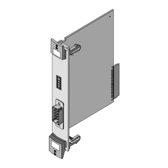
- Page 11 SPC200-MMI-DIAG User instructions The diagnostic module type SPC200-MMI-DIAG is designed for diagnosing the SPC200 Smart Positioning Controller. The diagnostic module has 2 serial interfaces. One interface is for connection to a type SPC-MMI-1 control panel and the other is for connection to a PC. The serial interface for the PC is in the form of a 9-pin Submin-D connector and complies with standard RS-232.
- Page 12 SPC200-MMI-DIAG Fitting and removing the modules CAUTION Modules can be damaged by incorrect handling. • Do not touch any of the components. • Follow the instructions for handling components which are affected by electrostatic charges. • Discharge yourself electrostatically before inserting or removing modules in order to protect the components from discharges of static electricity.
- Page 13 SPC200-MMI-DIAG Fitting the modules 1. Switch off the compressed air supply and operating voltage supply. 2. If necessary unlock the safety catches and remove any blank panels. 3. Take hold of the front plate of the module and slide it into the guide rail.
- Page 14 – no handshake For connection to a PC you will need: – a screened connecting cable (e.g. a Festo diagnostic cable type KDI-PPA-3-BU9) – a PC with a serial interface (RS-232) with WinPISA pro- gramming and commissioning sortware type P.SW-WIN- PISA-..
- Page 15 SPC200-MMI-DIAG Pin assignment of the (X4) serial interface Pin 2: Received Data (RxD) Pin 3: Transmitted Data (TxD) Pin 5: Signal Ground (SGND) Connect the diagnostic cable as follows: – 9-pin connector to the 9-pin socket on the module –...
- Page 16 SPC200-MMI-DIAG Connection to the control panel (X3) The type SPC200-MMI-... control panel can be plugged directly to the upper interface with the power switched off. CAUTION Connecting the control panel with the power on can damage the control panel. Switch off the operating voltage supply before you plug in the control panel.
-
Page 17: Technical Specifications
SPC200-MMI-DIAG Technical specifications Type SPC200-MMI- DIAG Temperature range: - operating C ... + 50 - storage/transport C ... + 70 Weight 68 g Relative humidity 95 % non-condensing Serial interface (RS232C) - baud rates 9600, 19200, 38400, 57600, 115200 baud... - Page 18 SPC200-MMI-DIAG 9804NH...
Need help?
Do you have a question about the SPC200-MMI-DIAG and is the answer not in the manual?
Questions and answers