Table of Contents
Advertisement
Available languages
Available languages
Quick Links
Advertisement
Table of Contents

Related Manuals for Festo SLG-Z Series


Summary of Contents for Festo SLG-Z Series
- Page 1 Zwischenpositionsmodul Intermediate position module SLG−Z−... (de) Bedienungs− anleitung (en) Operating instructions (es) Instrucciones de utilización (fr) Notice d’utilisation (it) Istruzioni per l’uso (sv) Bruksanvisning 700 544 0512a...
- Page 2 ..............Festo SLG−Z−... 0512a...
-
Page 3: Bedienteile Und Anschlüsse
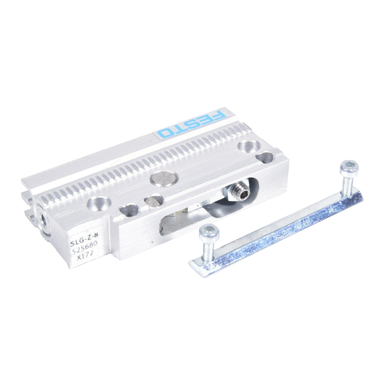
Anschlaghebel mit Anschlagelement Nuten für Näherungsschalter Zahnprofil zur groben Positionierung Zentrierbohrungen (zur Positionierung ohne Befestigungsschiene Typ SLG−...−S−...) Anschlagelement mit Anschlagteller Gewinde zur Feinjustierung des Anschlagelements (mit Kontermutter gesichert) Befestigungsbohrungen (Nutensteine und Befestigungsschrauben im Lieferumfang enthalten) Bild 1 Festo SLG−Z−... 0512a Deutsch... -
Page 4: Funktion Und Anwendung
Abfangen von Massekräf Bild 3 ten in einer Stellung zwischen den Endlagen von Linearantrieben (z. B. in Verbindung mit dem Zwischenpositionsbaukasten bei einer Schlitteneinheit Typ SLG−...). Innerhalb der zugelassenen Belastungsgrenzen wirkt das Zwischenpositionsmodul auch als Anschlag. Festo SLG−Z−... 0512a Deutsch... -
Page 5: Voraussetzungen Für Den Produkteinsatz
Durch unlösbaren Schmutz schwenkt un ter Umständen der Hebel schwergängig. Bild 5 Belüften Sie die Anlage insgesamt lang sam. Dazu dient das Einschaltventil Typ HEL−..Verwenden Sie das Produkt im Originalzu stand ohne jegliche eigenmächtige Verän derung. Bild 6 Festo SLG−Z−... 0512a Deutsch... -
Page 6: Einbau
Gummipuffer) in den Dämpferhalter ein schieben. Bild 8 Beim Nachrüsten einer vorhandenen Schlitteneinheit Typ SLG−... können die Stoßdämpfer der Schlitteneinheit verwen det werden. Diese mit einem Schrauben dreher heraushebeln und in den Dämpfer Bild 9 halter schieben (siehe Bild 9). Festo SLG−Z−... 0512a Deutsch... - Page 7 Profilkante (C) anlegen, mit Pass−Stiften (D) positionieren und an allen Befesti− gungsbohrungen mit Schrauben befesti gen. Die Auflagefläche muss eben sein (siehe Bedienungsanleitung SLG−...). Die Anziehdrehmomente sind in nachfol SLG−S−... gender Tabelle zusammengefasst: Bild 12 Bild 13 Festo SLG−Z−... 0512a Deutsch...
- Page 8 Anschlüsse X einzuhalten (siehe Bild 17). Bild 16 SLG−Z−... 8−... 12−... 18−... Mindestabstand zum Einschwenken des Anschlaghebels X 23 mm 23 mm 31 mm für die Verschraubung X 16 mm 16 mm 16 mm Bild 17 Festo SLG−Z−... 0512a Deutsch...
- Page 9 S Stellen Sie sicher, dass sich der Schlitten des Linearantriebs beim Einfahren des Anschlaghebels außerhalb des Schwenkbereichs befindet (z. B. durch eine schaltungstechnische Ansteuerungsverzögerung). Die Einschwenkgeschwindigkeit des Anschlaghebels übersteigt die Schlitten geschwindigkeit der Schlitteneinheit SLG−..Festo SLG−Z−... 0512a Deutsch...
- Page 10 Schlitten des Linearantriebs außerhalb des Schwenkbereichs des Anschlaghebels. Hinweis Beim Einfahren des Anschlaghebels können Gliedmaßen eingeklemmt wer den. S Stellen Sie sicher, dass im Verfahr− bereich des Anschlaghebels: niemand hineinfasst, sich keine Fremdgegenstände befinden. Bild 22 Festo SLG−Z−... 0512a Deutsch...
- Page 11 Taktfrequenz und geringer Auftreffgeschwindigkeit. 6. Beschleunigen Sie die Nutzlast schrittweise, bis zur späteren Betriebs− geschwindigkeit. Diese entnehmen Sie bitte der Berechnung zu Ihrem Einsatzfall. Der Schlitten des Linearantriebs darf dabei nicht hart am Zwischenpositions modul SLG−Z−... anschlagen. Festo SLG−Z−... 0512a Deutsch...
-
Page 12: Bedienung Und Betrieb
Beim Einsatz des Zwischenstellungsmoduls mit Gummipuffer: Berücksichtigen Sie, dass sich bei längerem Betrieb die Endlagenposition durch die dauerhafte Verformung des Gummipuffers ändert. Bei schrägen oder senkrechten Einbaufällen: Verwenden Sie die Dämpfungsvariante mit Stoßdämpfer vom Typ YSRG−..Festo SLG−Z−... 0512a Deutsch... -
Page 13: Wartung Und Pflege
Teile des Baukasten mit einem weichen Lappen. Zulässige Reinigungsmedien sind: Seifenlauge (max. 60 °C) Alle werkstoffschonenden Medien. Ausbau und Reparatur Zum Ausbau: Entlüften Sie die Anlage und das Gerät. Bei Bedarf: Schicken Sie die SLG−Z−... an unseren Reparaturservice. Festo SLG−Z−... 0512a Deutsch... - Page 14 Position der Näherungs− Position der Näherungsschalter Positionsabfrage schalter falsch korrigieren Falscher Näherungsschalter− Nur Näherungsschalter vom Typ eingesetzt Typ SME/SMT−10−... verwenden Näherungsschalter defekt Näherungsschalter tauschen Ferritische Teile in der Nähe Teile aus nichtmagnetischen des Näherungsschalters Werkstoffen einsetzen Bild 27 Festo SLG−Z−... 0512a Deutsch...
-
Page 15: Technische Daten
− 10 °C ... max. + 60 °C Werkstoffe Gehäuse: Al (eloxiert) Zahnstange Ritzel: Schrauben, Nutenstein: Dichtungen: Gummipuffer: Gewicht (SLG−...−Z..) 33,5 g 33,5 g 75 g Bild 28 Bei 6 bar und T = 20 °C Festo SLG−Z−... 0512a Deutsch... - Page 16 SLG−Z−... Festo SLG−Z−... 0512a Deutsch...
-
Page 17: Operating Parts And Connections
Centring holes (for positioning without fastening rail type SLG−...−S−...) Stop with stop plate Thread for accurate adjustment of the stop (secured with locking nuts) Fastening holes (sliding blocks and fastening screws included in delivery) Fig. 1 Festo SLG−Z−... 0512a English... - Page 18 (e.g. in conjunction with the intermedi ate position sets with a slide unit type SLG−...). Within the permitted loading limits, the intermediate position module also func tions as a stop. Festo SLG−Z−... 0512a English...
-
Page 19: Conditions Of Use
If dirt is not removed, the lever may only swivel with difficulty. Fig. 5 Slowly pressurize the complete system. To do this use start−up valve type HEL−..Use the product in its original state. Un authorized modification is not permitted. Fig. 6 Festo SLG−Z−... 0512a English... - Page 20 When retrofitting an existing slide unit type SLG−... , you can use the shock ab sorbers of the slide unit. Lift these out with a screwdriver and push them into the cushioning support (see Fig. 9). Fig. 9 Festo SLG−Z−... 0512a English...
- Page 21 (D) and tighten with screws in all the fastening holes. The supporting surface must be level (see operating in structions for type SLG−...). The tightening torques are shown in the SLG−S−... table below: Fig. 12 Fig. 13 Festo SLG−Z−... 0512a English...
- Page 22 (see Fig. 17). Fig. 16 SLG−Z−... 8−... 12−... 18−... Minimum distance for swivelling the stop lever X 23 mm 23 mm 31 mm for thescrew connection X 16 mm 16 mm 16 mm Fig. 17 Festo SLG−Z−... 0512a English...
- Page 23 S Make sure that the slide of the linear drive is outside the swivel range when the stop lever moves in (e.g. by means of a control delay circuit). The swivel−in speed of the stop lever exceeds the slide speed of the slide unit type SLG−..Festo SLG−Z−... 0512a English...
- Page 24 S Make sure that: nobody can place his/her hand in the positioning range of the stop lever. there are no objects in the position− ing range of the stop lever. Fig. 22 Festo SLG−Z−... 0512a English...
- Page 25 6. Accelerate the work load in steps until the operating speed is reached. Please refer to your application for these speeds. The slide of the linear drive must not strike hard against the intermediate posi tion module type SLG−Z−..Festo SLG−Z−... 0512a English...
-
Page 26: Operation
Take into account the fact that the end position will change after long periods of operation due to the continuous deformation of the rubber buffer. With diagonal or vertical fitting of the module. Use the cushioning variant with shock absorber type YSRG−..Festo SLG−Z−... 0512a English... -
Page 27: Care And Maintenance
Permitted cleaning agents are: soap suds (max. 60 °C) all non−abrasive agents. Dismantling and repairs Dismantling Exhaust the complete system and the module. If required: Return the SLG−Z−... to our repair service for overhaul. Festo SLG−Z−... 0512a English... -
Page 28: Eliminating Faults
Incorrect type of proximity Use only proximity switches of switched used type SME/SMT−10−... Proximity switch defective Replace proximity switch Ferritic parts in vicinity of Use parts made of non− proximity switch magnetic materials Fig. 27 Festo SLG−Z−... 0512a English... -
Page 29: Technical Specifications
− 10 ... max. + 60 °C Materials Housing: Al (anodized) Toothed rod: Pinion: Screws, sliding block: Seals: Rubber buffer: Weight (SLG−...−Z..) 33.5 g 33.5 g 75 g Fig. 28 At 6 bar and T = 20 °C Festo SLG−Z−... 0512a English... - Page 30 SLG−Z−... Festo SLG−Z−... 0512a English...
- Page 31 Agujeros de centraje (para posicionamiento sin raíl de fijación tipo SLG−...−S−...) Tope con placa de detención Rosca para ajuste preciso del tope (asegurado con contratuercas) Agujeros de fijación (bloques deslizantes y tornillos de fijación incluidos en el suministro) Fig. 1 Festo SLG−Z−... 0512a Español...
- Page 32 (p. ej. en combinación con los conjuntos de posiciones intermedias con una corredera tipo SLG−...). Dentro de los límites de carga permisibles, el módulo de posición intermedia también funciona como tope. Festo SLG−Z−... 0512a Español...
-
Page 33: Condiciones De Utilización
Aplicar presión lentamente a todo el sis tema. Para ello, utilice la válvula de arran que tipo HEL−..Utilice el producto en su estado original. No se permiten modificaciones no autori Fig. 6 zadas. Festo SLG−Z−... 0512a Español... -
Page 34: Montaje
Cuando se aplique posteriormente a una unidad de corredera tipo SLG−... , puede utilizar los amortiguadores de la unidad de corredera. Levántelos con un destorni llador y colóquelos en el soporte de amor Fig. 9 tiguación (véase Fig. 9). Festo SLG−Z−... 0512a Español... - Page 35 La superfi cie de soporte debe estar nivelada (vé anse las instrucciones de funcionamiento para el tipo SLG−...). SLG−S−... Los pares de apriete se muestran en la Fig. 12 tabla inferior: Fig. 13 Festo SLG−Z−... 0512a Español...
- Page 36 Fig. 16 SLG−Z−... 8−... 12−... 18−... Distancia mínima para el basculamiento de la palanca de tope X 23 mm 23 mm 31 mm para la conexión atornillada X 16 mm 16 mm 16 mm Fig. 17 Festo SLG−Z−... 0512a Español...
- Page 37 (p. ej. por medio de un circuito temporizador). La velocidad de basculamiento de la palanca de tope sobrepasa la velocidad de la corredera de la unidad tipo SLG−..Festo SLG−Z−... 0512a Español...
-
Page 38: Puesta A Punto
S Asegúrese de que: nadie pueda poner sus manos en el margen de posicionado de la palanca de tope no haya objetos en el margen de posicionado de la palanca de tope. Fig. 22 Festo SLG−Z−... 0512a Español... - Page 39 6. Acelerar la carga de trabajo en etapas hasta alcanzar la velocidad de funciona miento. Estas velocidades dependerán de cada aplicación. La corredera del actuador lineal no debe golpear duro contra el módulo de posición intermedia tipo SLG−Z−..Festo SLG−Z−... 0512a Español...
- Page 40 Tener en cuenta el hecho que la posición final cambiará tras largos períodos de funcionamiento, debido a la continua deformación del tope de goma. Con el montaje vertical o en diagonal del módulo: Utilice la variante de amortiguación con amortiguador tipo YSRG−..Festo SLG−Z−... 0512a Español...
-
Page 41: Cuidados Y Mantenimiento
( máx. 60 °C) cualquier agente no abrasivo. Desmontaje y reparaciones Desmontaje: Descargar el aire de todo el sistema y del módulo. Si es necesario: Devolver el SLG−Z−... a nuestro servicio técnico para su reparación. Festo SLG−Z−... 0512a Español... -
Page 42: Eliminación De Fallos
Tipo incorrecto de detectores Usar sólo detectores de proxi de proximidad midad del tipo SME/SMT−10−... Detector de proximidad Reemplazar el detector de defectuoso proximidad Piezas ferríticas cerca del Usar piezas de materiales no detector de proximidad ferríticos Fig. 27 Festo SLG−Z−... 0512a Español... -
Page 43: Especificaciones Técnicas
− 10 °C ... máx. + 60 °C Materiales Cuerpo: Al (anodizado) Barra dentada: Piñón: Acero Tornillos, bloque deslizante: Acero Juntas: Tope de goma: Peso (SLG−...−Z..) 33,5 g 33,5 g 75 g Fig. 28 A 6 bar y T = 20 °C Festo SLG−Z−... 0512a Español... - Page 44 SLG−Z−... Festo SLG−Z−... 0512a Español...
- Page 45 Trou de centrage (pour le positionnement sans rail de fixation type SLG−...−S_...) Elément de butée avec disque de butée Filetage pour ajuster avec précision l’élément de butée (fixé à l’aide d’un contre−écrou) Trous de fixation (tasseaux et vis de fixation compris dans les fournitures) Fig. 1 Festo SLG−Z−... 0512a Français...
-
Page 46: Fonctionnement Et Application
SLG−...). Si l’on respecte les limites de charge admissi bles, le module de positionnement intermé diaire peut également servir de butée pour d’autres applications. Festo SLG−Z−... 0512a Français... -
Page 47: Conditions De Mise En Uvre Du Produit
à actionner. Mettre l’installation lentement sous pres sion. Utiliser pour cela le distributeur de type HEL−..démarrage Utiliser le produit dans son état d’origine sans apporter de modifications. Fig. 6 Festo SLG−Z−... 0512a Français... -
Page 48: Montage
SLG−... existant, il est possible d’utili ser les amortisseurs du chariot. Il suffit alors de les retirer en faisant levier à l’aide d’un tournevis et de les placer dans le support d’amortisseur (voir Fig. 9). Fig. 9 Festo SLG−Z−... 0512a Français... - Page 49 La surface d’appui doit être plane (voir notice d’utilisation SLG−...). Les couples de serrage sont indiqués dans SLG−S−... Fig. 12 le tableau ci−dessous : Fig. 13 Festo SLG−Z−... 0512a Français...
- Page 50 (voir Fig. 17). Fig. 16 SLG−Z−... 8−... 12−... 18−... Ecart minimum pour pouvoir actionner le levier de butée X 23 mm 23 mm 31 mm pour le raccord X 16 mm 16 mm 16 mm Fig. 17 Festo SLG−Z−... 0512a Français...
- Page 51 (p. ex. grâce à une temporisation de pilotage par commutation). La vitesse d’actionnement du levier de butée est supérieure à la vitesse de déplacement du chariot SLG−..Festo SLG−Z−... 0512a Français...
-
Page 52: Mise En Service
S S’assurer que dans la zone d’action nement du levier de butée : personne n’entre en contact avec cette zone, aucun corps étranger ne se trouve dans cette zone. Fig. 22 Festo SLG−Z−... 0512a Français... - Page 53 Pour connaître celle−ci, la calculer pour chaque cas réel. Il faut de plus veiller à ce que le chariot de l’entraînement linéaire ne bute pas de manière brutale contre le module de positionnement intermédiaire SLG−Z−..Festo SLG−Z−... 0512a Français...
-
Page 54: Conditions D'utilisation
Noter que lors d’un fonctionnement prolongé la position de fin de course est modifiée par la déformation durable du tampon en caoutchouc. En cas de montage incliné ou vertical : Utiliser la variante avec amortisseur de type YSRG−..Festo SLG−Z−... 0512a Français... -
Page 55: Maintenance Et Entretien
Les produits de nettoyage autorisés sont les suivants : eau savonneuse (max. 60 °C), tous les produits d’entretien des matériaux. Démontage et réparation Pour le démontage : Mettre l’installation et l’appareil à l’échappement. Si nécessaire : Envoyer le SLG−Z−... à notre service après−vente. Festo SLG−Z−... 0512a Français... -
Page 56: Dépannage
SME/SMT−10−... Capteur de proximité Remplacer le capteur de défectueux proximité Pièces ferritiques près du Utiliser des pièces fabriquées capteur de proximité avec des matériaux non magnétiques Fig. 27 Festo SLG−Z−... 0512a Français... -
Page 57: Caractéristiques Techniques
Al (anodisé) Crémaillère : Pignon : Acier Vis, tasseau : Acier Joints d’étanchéité : Tampon en caoutchouc : Poids (SLG−...−Z..) 33,5 g 33,5 g 75 g Fig. 28 Pour 6 bar et T = 20 °C Festo SLG−Z−... 0512a Français... - Page 58 SLG−Z−... Festo SLG−Z−... 0512a Français...
- Page 59 Elemento di riscontro con superficie di battuta Filetto per la regolazione di precisione dell’elemento di riscontro (provvisto di dado di bloccaggio) Fori di fissaggio (i tasselli scorrevoli e le viti di fissaggio sono comprese nella fornitura) Fig. 1 Festo SLG−Z−... 0512a Italiano...
-
Page 60: Funzionamento E Utilizzo
(ad es. in combinazione con il sistema modu lare di posizionamento intermedio di un at tuatore lineare senza stelo tipo SLG−...). Quando il carico rientra nei limiti consentiti, il modulo di posizionamento intermedio svolge anche la funzione di arresto meccanico. Festo SLG−Z−... 0512a Italiano... -
Page 61: Condizioni Di Utilizzo
Fig. 5 compromettendone il funzionamento. Alimentare gradualmente l’impianto. Utilizzare a tal scopo la valvola di avvia mento tipo HEL−..Utilizzare il prodotto nel suo stato originale, senza apportare modifiche non autorizzate. Fig. 6 Festo SLG−Z−... 0512a Italiano... - Page 62 Per il potenziamento di un attuatore li neare senza stelo SLG−... già installato è possibile utilizzare gli ammortizzatori dell’attuatore. Tali ammortizzatori vanno sfilati con l’ausilio di un cacciavite e inse Fig. 9 riti nel supporto (v. Fig. 9). Festo SLG−Z−... 0512a Italiano...
- Page 63 La superficie di fissaggio deve essere piana (vedere le istruzioni SLG−S−... d’uso dell’SLG−...). Fig. 12 Nella seguente tabella sono riportati i valori di coppia di serraggio da applicare: Fig. 13 Festo SLG−Z−... 0512a Italiano...
- Page 64 X (v. Fig. 17). SLG−Z−... 8−... 12−... 18−... Distanza minima per l’abbassamento della leva di arresto X 23 mm 23 mm 31 mm per il raccordo filettato X 16 mm 16 mm 16 mm Fig. 17 Festo SLG−Z−... 0512a Italiano...
- Page 65 (ad es. impostando un ritardo di azionamento). La velocità di abbassamento della leva di arresto è maggiore della velocità di traslazione del cursore dell’attuatore lineare senza stelo SLG−..Festo SLG−Z−... 0512a Italiano...
-
Page 66: Messa In Servizio
La leva di arresto abbassandosi può causare lo schiacciamento di arti. S Predisporre adeguate misure per im pedire che nell’area di traslazione della leva di arresto: si possano inserire le mani possano penetrare dei corpi estranei. Fig. 22 Festo SLG−Z−... 0512a Italiano... - Page 67 6. Accelerare gradualmente il carico, fino a raggiungere la velocità di regime prevista. Quest’ultima va calcolata in relazione all’applicazione specifica. Il cursore dell’attuatore lineare non raggiungere il modulo di posizionamento intermedio SLG−Z−... con una forza di impatto ecccessiva. Festo SLG−Z−... 0512a Italiano...
-
Page 68: Uso E Funzionamento
In caso di utilizzo prolungato, la posizione di fine corsa può modificarsi a causa della continua deformazione del tampone in gomma. In caso di montaggio in posizione inclinata o verticale: Per ottenere la decelerazione, utilizzare l’ammortizzatore tipo YSRG−..Festo SLG−Z−... 0512a Italiano... -
Page 69: Cura E Manutenzione
Detergenti ammissibili sono: acqua saponata (max. 60 °C) tutti i detergenti non aggressivi. Smontaggio e riparazione Prima di procedere allo smontaggio: Scaricare la pressione dall’impianto e dal dispositivo. All’occorrenza: Inviare l’SLG−Z−... al nostro servizio di assistenza tecnica. Festo SLG−Z−... 0512a Italiano... -
Page 70: Eliminazione Dei Guasti
Non sono stati utilizzati i Utilizzare esclusivamente i finecorsa corretti finecorsa magnetici tipo SME/SMT−10−..Finecorsa magnetico Sostituire il finecorsa magne difettoso tico. Presenza di componenti ferri Installare componenti in tici in prossimità del finecorsa materiale antimagnetico. magnetico Fig. 27 Festo SLG−Z−... 0512a Italiano... -
Page 71: Dati Tecnici
Materiali Corpo : Alluminio (anodizzato) Cremagliera: Pignoni: Acciaio Viti, tassello scorrevole: Acciaio Guarnizioni: Tampone in gomma: Peso (SLG−...−Z..) 33,5 g 33,5 g 75 g Fig. 28 A 6 bar e con una temperatura di 20 °C. Festo SLG−Z−... 0512a Italiano... - Page 72 SLG−Z−... Festo SLG−Z−... 0512a Italiano...
- Page 73 Tryckluftanslutning Anslagsarm med dämpningselement Spår för cylindergivare Kuggprofil för grovinställning Centreringshål (för positionering utan fästskena SLG−...−S−...) Dämpningselement med dämpskiva Gänga för finjustering av dämpningselementet (säkrad med kontramutter) Fästhål (spårmuttrar och fästskruvar ingår i leveransen) Bild 1 Festo SLG−Z−... 0512a Svenska...
- Page 74 3. Mellanlägesmodulen är avsedd för att fånga upp massakrafter i ett läge mellan linjärenhe ternas ändlägen (t ex i kombination med mel lanlägesbyggsatsen och linjärenhet SLG−...). Bild 3 Inom godkända belastningsgränser fungerar mellanlägesmodulen även som anslag. Festo SLG−Z−... 0512a Svenska...
- Page 75 Använd SLG−Z−... i en ren omgivning. Bild 5 Smutsig omgivning kan leda till att anslagsarmen går trögt. Pålufta hela anläggningen långsamt. Mjukstartventil HEL−... är avsedd för detta. Använd produkten i originalskick utan egna modifieringar. Bild 6 Festo SLG−Z−... 0512a Svenska...
- Page 76 1. Skjut in dämpelementen (stötdämpare eller gummianslag) i dämparfästet. Bild 8 Vid eftermontering av en befintlig linjär− enhet SLG−... kan enhetens stötdämpare användas. Avlägsna stötdämparna med en skruvmejsel och skjut in dem i dämpar fästet (se Bild 9). Bild 9 Festo SLG−Z−... 0512a Svenska...
- Page 77 Lägg fästskena SLG−S−... mot profilkanten (C), positionera med passtift (D) och fixera i alla fästhål med skruvar. Anligg ningsytan måste vara jämn (se bruks− anvisning för SLG−...). Åtdragningsmomenten är sammanfattade i följande tabell: SLG−S−... Bild 12 Bild 13 Festo SLG−Z−... 0512a Svenska...
- Page 78 X (se Bild 17). Bild 16 SLG−Z−... 8−... 12−... 18−... Minimiavstånd för insvängning av anslagsarm X 23 mm 23 mm 31 mm för instickskoppling X 16 mm 16 mm 16 mm Bild 17 Festo SLG−Z−... 0512a Svenska...
- Page 79 Styrteknisk montering Notera Anslagsarmen kan förstöra stötdämparen vid inkörning. S Se till att linjärenhetens åkvagn befinner sig utanför svängområdet när anslagsarmen svängs in (t ex genom en kopplingsteknisk styrfördröjning). Anslagsarmens insvängningshastighet överstiger vagnhastigheten på linjärenhet SLG−..Festo SLG−Z−... 0512a Svenska...
- Page 80 Anslagsarmen körs ut i rätt tid. Linjärenhetens åkvagn befinner sig utanför anslagsarmens svängom− råde. Notera När anslagsarmen svängs in finns risk för klämskador. S Säkerställ inom anslagsarmens svängområde att: Inga fingrar är i vägen Inga främmande föremål före− kommer Bild 22 Festo SLG−Z−... 0512a Svenska...
- Page 81 5. Gör en provkörning enligt linjärenhetens bruksanvisning med låg taktfrekvens och låg anslagshastighet. 6. Accelerera arbetslasten stegvis, tills driftshastigheten nås. Driftshastigheten framgår av beräkningen för din applikation. Linjärenhetens åkvagn får därvid inte slå an hårt mot mellanlägesmodul SLG−Z−..Festo SLG−Z−... 0512a Svenska...
-
Page 82: Manövrering Och Drift
8. Avsluta provkörningen. Manövrering och drift Vid användning av mellanlägesmodulen med gummianslag: Ta hänsyn till att ändläget förändras vid längre drift pga. kontinuerligt slitage av gummianslaget. Vid sned eller vertikal montering: Använd dämpningsvarianten med stötdämpare YSRG−..Festo SLG−Z−... 0512a Svenska... -
Page 83: Underhåll Och Skötsel
Rengör mellanlägesmodulen och andra delar av byggsatsen med ett mjukt tygstycke vid nedsmutsning. Tillåtna rengöringsmedel är: Tvållösning (max 60 °C) Alla materialskonande medel Demontering och reparation För demontering: Avlufta anläggningen och modulen. Vid behov: Skicka SLG−Z−... till vår reparationsservice. Festo SLG−Z−... 0512a Svenska... -
Page 84: Åtgärdande Av Störningar
Störningar vid Cylindergivarnas position Korrigera cylindergivarnas positionsavläsning felaktig position Fel cylindergivartyp används Använd endast cylindergivare SME/SMT−10−... Cylindergivare defekt Byt cylindergivare Ferritiska delar i närheten av Använd endast komponenter cylindergivare av tillverkningsmaterial som inte är magnetiskt Bild 27 Festo SLG−Z−... 0512a Svenska... -
Page 85: Tekniska Data
− 10 °C ... max + 60 °C Material Hus: Al (anodoxiderad) Kuggstång: Kuggdrev: Skruvar, spårmutter: Tätningar: Gummianslag: Vikt (SLG−...−Z..) 33,5 g 33,5 g 75 g Bild 28 Vid 6 bar och T = 20 °C Festo SLG−Z−... 0512a Svenska... - Page 86 SLG−Z−... Festo SLG−Z−... 0512a Svenska...
- Page 87 SLG−Z−... Festo SLG−Z−... 0512a...
- Page 88 Copyright: autorisation écrite expresse. Tout manquement à cette règle Festo AG & Co., est illicite et expose son auteur au versement de dommages Postfach 6040 et intérêts. Tous droits réservés pour le cas de la délivrance D−73726 Esslingen...
Need help?
Do you have a question about the SLG-Z Series and is the answer not in the manual?
Questions and answers