
Related Manuals for Festo Soft Stop SPC11 Series


Summary of Contents for Festo Soft Stop SPC11 Series
- Page 1 Soft Stop SPC11 Manual Electronics/ pneumatics System manual Soft Stop Type SPC11-...-...-ASI Manual 529 065 en 0203NH [657 851]...
- Page 3 ....... . . 529 065 E (Festo AG & Co., D-73726 Esslingen, Federal Republic of Germany, 2002) Internet: http://www.festo.com...
- Page 4 Contents and general instructions Trademarks ® Temposonics is a registered trademark of MTS Sensortechnologie GmbH & Co ® AS-Interface is a registered trademark of AS-International Association. Festo P.BE-SPC11-SYS-ASI-EN en 0203NH...
-
Page 5: Table Of Contents
......... . . 3-31 Festo P.BE-SPC11-SYS-ASI-EN en 0203NH... - Page 6 ............Festo P.BE-SPC11-SYS-ASI-EN en 0203NH...
-
Page 7: Designated Use
When used together with commercially available compo- nents, such as sensors and actuators, the specified limits for pressures, temperatures, electrical data, torques etc. must be observed. National and local safety regulations must also be observed. Festo P.BE-SPC11-SYS-ASI-EN en 0203NH... -
Page 8: Service
Contents and general instructions Service Please consult your local Festo repair service if you have any technical problems. Target group This manual is directed exclusively at technicians trained in control and automation technology. Festo P.BE-SPC11-SYS-ASI-EN en 0203NH... -
Page 9: Important User Instructions
This means that failure to observe this instruction may result in damage to property. The following pictogram marks passages in the text which describe activities with electrostatically sensitive compo- nents. Electrostatically sensitive components may be damaged if they are not handled correctly. Festo P.BE-SPC11-SYS-ASI-EN en 0203NH... - Page 10 Accessories: Information on necessary or sensible accessories for the Festo product. Environment: Information on environment-friendly use of Festo products. Text markings The bullet indicates activities which may be carried out in any order. 1. Figures denote activities which must be carried out in the numerical order specified.
-
Page 11: Product-Specific Terms And Abbreviations
The I/O code defines how the four data bits from the AS-Interface protocol are to be used. Together with the ID code an AS-Interface slave can therefore be identified clearly. Nibble An information unit consisting of four bits is called a nibble. Digital output Festo P.BE-SPC11-SYS-ASI-EN en 0203NH... - Page 12 Teach procedure During the teach procedure the SPC11 checks the set parameters, learns the position of the mechanical fixed stops as well as various characteristic system values and saves these in the integrated EEPROM. Festo P.BE-SPC11-SYS-ASI-EN en 0203NH...
-
Page 13: Notes On The Use Of This Manual
SPC11. Please note For installation and commissioning you will require the system manual as well as the manual “Drive-specific sup- plement” for the drive used. Festo P.BE-SPC11-SYS-ASI-EN en 0203NH... - Page 14 Contents and general instructions Festo P.BE-SPC11-SYS-ASI-EN en 0203NH...
-
Page 15: Summary Of Components
Summary of components Chapter 1 Festo P.BE-SPC11-SYS-ASI-EN en 0203NH... - Page 16 ..... . Method of working as an AS-Interface slave ......1-10 Festo P.BE-SPC11-SYS-ASI-EN en 0203NH...
-
Page 17: Structure
Enables connection to the connecting rod potentiometer type MLO-POT-...-LWG and the rotary drive with integrated measuring system type DSMI-..SPC11-MTS-AIF-ASI Enables connection of the linear drive with integrated digital measuring system type DGPI(L)-...-...-...-AIF or the digital measuring system type MME-MTS-...-AIF. Festo P.BE-SPC11-SYS-ASI-EN en 0203NH... - Page 18 With the SPC11, positioning is made with closed-loop control. During commissioning, the end positions (cylinder end posi- tions or position of the fixed stops) as well as the desired intermediate positions are “learnt” by the SPC11. Festo P.BE-SPC11-SYS-ASI-EN en 0203NH...
- Page 19 (shock absorbers) – the maintenance of fixed stops. Compared with pneumatic-impact drives with double-sole- noid control, the SPC11 permits: – higher machine cycle times – less vibration of the system – lower maintenance costs. Festo P.BE-SPC11-SYS-ASI-EN en 0203NH...
- Page 20 – a drive, if possible with mechanical guide – if possible, two fixed stops (depending on the drive used) – a 24 V DC power supply – if possible, components for a pneumatic emergency stop circuit. Festo P.BE-SPC11-SYS-ASI-EN en 0203NH...
-
Page 21: Method Of Operation
In the following text, the term “moveable mass” also repre- sents the terms piston, slide and flange shaft. The following diagram shows the basic layout of a positioning control circuit with the SPC11. Festo P.BE-SPC11-SYS-ASI-EN en 0203NH... - Page 22 The proportional directional control valve controls the drive by pressurizing one cylinder chamber and exhausting the other. The flow is blocked in the valve slide mid-position. Festo P.BE-SPC11-SYS-ASI-EN en 0203NH...
-
Page 23: Display And Connecting Elements On The Spc11
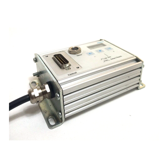
PLC/IPC (type IBS 6x10) Valve: Valve connection ASI LED (bus status, green), Fault LED (fault, red) Display Measuring system connection Operating buttons Earth/ground connection Fig. 1/3: Display and connecting elements of the SPC11 Festo P.BE-SPC11-SYS-ASI-EN en 0203NH... -
Page 24: Method Of Working As An As-Interface Slave
SPC11 via the AS-Interface bus. If you wish to use slave profile 7.4, you will require an AS-In- terface master which supports this profile. 1-10 Festo P.BE-SPC11-SYS-ASI-EN en 0203NH... -
Page 25: Fitting
Fitting Chapter 2 Festo P.BE-SPC11-SYS-ASI-EN en 0203NH... - Page 26 ..........Festo P.BE-SPC11-SYS-ASI-EN en 0203NH...
-
Page 27: Fitting The Spc11
M4. Fasten the SPC11 with at least 3 screws. 118.4 mm approx. 91.8 mm 78 mm 63 mm 109.4 mm 42 mm Plug in fitted state Fig. 2/1: Fitting dimensions of the SPC11 Festo P.BE-SPC11-SYS-ASI-EN en 0203NH... - Page 28 2. Fitting Festo P.BE-SPC11-SYS-ASI-EN en 0203NH...
-
Page 29: Installation
Installation Chapter 3 Festo P.BE-SPC11-SYS-ASI-EN en 0203NH... - Page 30 ......... . . 3-31 Festo P.BE-SPC11-SYS-ASI-EN en 0203NH...
-
Page 31: General Instructions On Installation
2. the operating voltage. Caution The use of components which have not been passed for operation with the SPC11 may lead to malfunctioning. Use only the special matching components from Festo for setting up and wiring the system. Festo P.BE-SPC11-SYS-ASI-EN en 0203NH... -
Page 32: Notes On Installing The Pneumatic Components
Notes on installing the pneumatic components Please note Observe the following instructions on installing the pneu- matic components. Only then can you guarantee faultless operation. 1 ... 9 Notes on installation see the following pages Fig. 3/1: Overview of pneumatic installation Festo P.BE-SPC11-SYS-ASI-EN en 0203NH... - Page 33 (type MPYE-5-...), e.g.: Valve type Service unit MPYE-5-1/8-LF-010B LFR-M1-G1/8-C10RG or LFR-1/8-D-5M-MINI MPYE-5-1/8-HF-010B LFR-M1-G1/4-C10RG or LFR-1/4-D-5M-MINI MPYE-5-1/4-010B LFR-M2-G1/4-C10RG or LFR-3/8-D-5M-MIDI MPYE-5-3/8-010B LFR-M2-G3/8-C10RG or LFR-3/4-D-5M-MAXI Use a microfilter if you cannot avoid slight oil mist from the compressed air supply. Festo P.BE-SPC11-SYS-ASI-EN en 0203NH...
- Page 34 Reservoir volume: The reservoir volume should be at least four times as large as the volume of the drive used. = 4 * V buffer volume cylinder volume (linear drive: V * ð* L cylinder stroke length Festo P.BE-SPC11-SYS-ASI-EN en 0203NH...
- Page 35 1 bar are permitted in front of the proportional direc- tional control valve during positioning. In order to check the stability of the supply pressure, you can fit a pressure measuring point directly in front of the proportional direc- tional control valve. Festo P.BE-SPC11-SYS-ASI-EN en 0203NH...
- Page 36 MPYE-5-... when an SPC11 is used without an emergency stop circuit. Proportional directional control valve type MPYE-5-...-... Service unit with 5 µm filter without lubricator Fig. 3/2: Pneumatic circuit diagram Fit the valve in accordance with the operating instructions supplied with the valve. Festo P.BE-SPC11-SYS-ASI-EN en 0203NH...
- Page 37 Fitting at right angles to the direction of movement Not permitted Proportional directional control valve type MPYE-5-...-...- Fig. 3/3: Fitting to moving parts Use silencers with a large flow rate UC-M5, U-1/8, U-1/4 or U-3/8. Festo P.BE-SPC11-SYS-ASI-EN en 0203NH...
- Page 38 Make sure that there is sufficient flow through the screw connectors and tubing (with PUN-8 tubing length max. 1 m). Ducted exhaust Compressed air reservoir Silencer Fig. 3/4: Ducted exhaust 3-10 Festo P.BE-SPC11-SYS-ASI-EN en 0203NH...
- Page 39 3. Installation Drive ( 6 ) Use only the permitted combinations of drives and measuring systems approved of by Festo for the SPC11. The drive-valve combinations, cylinder diameters, cylinder lengths and mass loads permitted for the drive used can be found in the manual “Drive-specific supplement...
- Page 40 The remaining slide path of the measuring system must be identical in the cylinder end positions on both sides and can be calculated as follows: Calculation formula Description Measuring system length Cylinder length Remaining slide path 3-12 Festo P.BE-SPC11-SYS-ASI-EN en 0203NH...
- Page 41 (see type designation MME-MTS-...-AIF) of the measuring system is symmetrical to the complete cylinder stroke. Remaining slide path Electrical work path (usable stroke length) Mechanical work path (possible slide path) Fig. 3/6: Usable stroke length with type MME-MTS-...-AIF 3-13 Festo P.BE-SPC11-SYS-ASI-EN en 0203NH...
- Page 42 Fixed stops ( 8 ) Fixed stops may be necessary, depending on the drive used. See also “Drive-specific supplement.” Mass load ( 9 ) Fit the mass load free of play. Possible moveable mass loads see “Drive-specific supple- ment.” 3-14 Festo P.BE-SPC11-SYS-ASI-EN en 0203NH...
-
Page 43: Pneumatic Emergency Stop Circuit
Due to the asym- metrical voltage-pressure curve of the proportional direc- tional control valve when the supply pressure is switched on, the slide can move slowly into one of the end positions. 3-15 Festo P.BE-SPC11-SYS-ASI-EN en 0203NH... - Page 44 An emergency stop situ- ation is represented. Switching valve for emergency stop Emergency stop actuated Fig. 3/7: Switching off the operating pressure 3-16 Festo P.BE-SPC11-SYS-ASI-EN en 0203NH...
- Page 45 A in the event of an emergency stop.The emergency stop situation is represented here. Emergency stop actuated Fig. 3/8: Universal emergency stop circuit using the example of a linear drive 3-17 Festo P.BE-SPC11-SYS-ASI-EN en 0203NH...
- Page 46 Right-hand end position Connect compressed air Connect restrictor valve with silencer Left-hand end position Connect restrictor valve with Connect compressed air silencer Restrictor valves reduce impact forces in the event of failure of an emergency stop valve. 3-18 Festo P.BE-SPC11-SYS-ASI-EN en 0203NH...
-
Page 47: Installing The Electronic Components
Incorrect or missing earthing can cause interference. When using the DGP(L): Connect the cylinder type DGP(L)-... with low impedance (short cable with large cross-sectional area) to the earth potential, if the cylinder is not mounted on an earthed machine stand. 3-19 Festo P.BE-SPC11-SYS-ASI-EN en 0203NH... -
Page 48: Connecting Elements Of The Spc11
SPC11, using the SPC11-POT-TLF as an example. Measuring sys- tem connection (here for type MLO-POT-...-TLF) Earth/ground connection 24 V DC: Operating voltage connection Valve: Valve connection Bus: AS-Interface bus connection Fig. 3/9: Connecting elements of the SPC11 3-20 Festo P.BE-SPC11-SYS-ASI-EN en 0203NH... -
Page 49: Assigning The As-Interface Slave Addresses
The voltage required for the addressing is supplied by the addressing device. Recommendation: Use addressing device type ASI-PRG-ADR from Festo with adapter cable. Before connecting the SPC11 to the AS-Interface bus and the power supply, assign an unused AS-interface address to each slave. - Page 50 I/O code 7 input data (I1...I4) and output data (O1...O4) are transmitted bi-directionally via these 4 bits. Example of address assignment with control unit SF3 with AS-Interface master from Festo – I/O code: 7 – Slave address: #4...
- Page 51 .... Slave #31 Slave #30 Slave #30 Slave #31 Input byte Assigned addresses with I/O code 7 Output byte Fig. 3/11: Example of address assignment with AS-Interface master type CP 343-2 from Siemens 3-23 Festo P.BE-SPC11-SYS-ASI-EN en 0203NH...
-
Page 52: Selecting The Power Unit
Special power packs for AS-Interface bus systems enable energy and signals to be transmitted simultaneously on one cable. When selecting the devices, pay attention to the AS-In- terface logo. Recommendation: Use the Festo AS-interface combi power unit type ASI-CNT-115/230 VAC. 3-24 Festo P.BE-SPC11-SYS-ASI-EN en 0203NH... -
Page 53: Connecting The Operating Voltage And The As-Interface Bus
(short cable with large cross-sectional area) to the earth potential. S Connect a protective conductor with sufficient cross sectional area to the drive, if this is not mounted on an earthed machine stand. 3-25 Festo P.BE-SPC11-SYS-ASI-EN en 0203NH... - Page 54 EMERGENCY STOP (e.g. switching off the operating volt- age, switching off the compressed air). Seal open cable ends, e.g. with cable cap type ASI-KK-FK from Festo. In this way you will avoid leakage currents and comply with protection class IP65. Please note with branch lines: –...
- Page 55 The diagram below shows the pin assignment of the AS-Inter- face bus connection marked with “Bus” and of the operating voltage connection marked with “24 V DC.” 3-27 Festo P.BE-SPC11-SYS-ASI-EN en 0203NH...
- Page 56 3. Installation 24 V DC 0 V DC AS-i + (brown) AS-i - (light blue) Fig. 3/12: Pin assignment of the AS-Interface bus connection and of the load voltage connection 3-28 Festo P.BE-SPC11-SYS-ASI-EN en 0203NH...
- Page 57 3. Installation Connect a cable socket from Festo Recommendation: Use cable sockets type ASI-SD-FK or ASI- SD-FK180 from Festo. You will then comply with protection class IP65. Stick on identifi- cation labels type ISB6x10 Open the cable ISB6x10 socket (here...
- Page 58 AS-Interface bus (yellow cable) Operating voltage (black cable) AS-Interface combi power pack With linear drives, end position 1 lies on the side with the electrical connections to the measuring system Fig. 3/14: Connection example type SPC11-...-...-ASI 3-30 Festo P.BE-SPC11-SYS-ASI-EN en 0203NH...
-
Page 59: Connecting The Proportional Directional Control Valve And The Measuring System
3.3.5 Connecting the proportional directional control valve and the measuring system Connecting the measuring system Use only the permitted combinations of drives and measuring systems approved of by Festo for the SPC11. The connecting cable for the measuring system is firmly connected to the SPC11. Please note Interference due to electromagnetic influences can be avoided if a short cable is used. - Page 60 24 V supply for the valves (white) Fig. 3/15: Valve connection, pin assignment and core colours Fasten the plugs with the aid of the union nut in order to pre- vent unintentional loosening, e.g. due to shock. 3-32 Festo P.BE-SPC11-SYS-ASI-EN en 0203NH...
-
Page 61: Commissioning
Commissioning Chapter 4 Festo P.BE-SPC11-SYS-ASI-EN en 0203NH... -
Page 62: General Instructions On Commissioning
......... . . 4-32 4.4.4 Use the taught intermediate position as the sensor position ... . 4-37 Festo P.BE-SPC11-SYS-ASI-EN en 0203NH... -
Page 63: Commissioning
– the complete positioning range is free of any objects. Warning Incorrectly set parameters can damage the fixed stops and the drive. Be very careful when setting the parameters. Festo P.BE-SPC11-SYS-ASI-EN en 0203NH... - Page 64 System parameter Characteristic value for the structure of the drive. The parameters can be entered: – Before commissioning (pre-parametrizing without drive in the office). – When commissioning. Festo P.BE-SPC11-SYS-ASI-EN en 0203NH...
- Page 65 When the AS-Interface bus cable is connected and power is applied, the buttons of the SPC11 are blocked. If you use slave profile 7.4, you can carry out commissioning via the AS-Interface bus. Detailed information on this can be found in Appendix A. Festo P.BE-SPC11-SYS-ASI-EN en 0203NH...
- Page 66 The last two positions show the appropriate value, the stage or the number. Identifying letter for parameters (A, C, S) or status type Value, stage or status information Point for separation Fig. 4/1: Composition of the display on the SPC11 Festo P.BE-SPC11-SYS-ASI-EN en 0203NH...
- Page 67 The moveable mass stands in end position P.02 (opposite end position). The moveable mass stands in end position P.03 (taught intermediate position). The moveable mass stands in end position P.04 (taught intermediate position). Fault number (Error; value range: 01...14); see Chapter 5 Festo P.BE-SPC11-SYS-ASI-EN en 0203NH...
-
Page 68: Pre-Parametrizing In The Office
The SPC11 then expects the amplification stage to be entered. The display shows the letter A (Amplification stage). The figures indicate the stage (here 0). (A.00) 3. Now set the desired amplification stage with the buttons +/- (see axis-specific supplement), e.g. 02. (A.02) Festo P.BE-SPC11-SYS-ASI-EN en 0203NH... - Page 69 When all prerequisites for carrying out the teach procedure have been made (see sections 4.3.1), the teach procedure can be started (see sections 4.3.2). 9. If you wish to conclude pre-commissioning, switch off the operating voltage. Festo P.BE-SPC11-SYS-ASI-EN en 0203NH...
- Page 70 Wait approx. 1 second The t flashes The SPC11 waits for the teach task Fig. 4/2: Switch-on behaviour of the SPC11 after pre-commissioning (in the office) The teach procedure can be started (see section 4.3.1). 4-10 Festo P.BE-SPC11-SYS-ASI-EN en 0203NH...
-
Page 71: Modifying Parameters
Use the buttons as follows to activate the modification mode: 1. Make sure that the drive is standing still. 2. Press all three buttons on the SPC11 at the same time. 4-11 Festo P.BE-SPC11-SYS-ASI-EN en 0203NH... - Page 72 1. If necessary, switch off the compressed air and the power supplies. 2. Disconnect the measuring system cable from the measur- ing system. 3. Switch on the power supply. The SPC11 will then show fault E01 (measuring system not connected...). (E.01) 4-12 Festo P.BE-SPC11-SYS-ASI-EN en 0203NH...
- Page 73 With the buttons +/- you can set the value again and transfer it with Enter. The cushioning stage and the system parameter can then be set again in the same way and transferred (see section 4.2). 4-13 Festo P.BE-SPC11-SYS-ASI-EN en 0203NH...
-
Page 74: Procedure For Commissioning
– Make sure that the maximum permitted mass load is observed during operation. Recommendation: Place appropriate warning signs on your system. 4-14 Festo P.BE-SPC11-SYS-ASI-EN en 0203NH... -
Page 75: Preparations For The Teach Procedure
4. Check whether the parameters (amplification stage, cushioning stage and system parameter) have already been set correctly during pre-commissioning in accord- ance with the components used and the mass load to be moved. 4-15 Festo P.BE-SPC11-SYS-ASI-EN en 0203NH... - Page 76 The SPC11 then indicates readiness to carry out the teach procedure (t flashes). (The t flashes.) The teach procedure can now be started (see sections 4.3.2). 4-16 Festo P.BE-SPC11-SYS-ASI-EN en 0203NH...
-
Page 77: Starting The Teach Procedure
3. Now switch on the compressed air supply (5 to 7 bar). As the valve slide assumes the electrical mid-position, the moveable load can move slowly into one of the end posi- tions due to the asymmetrical voltage-pressure curve of the proportional directional control valve. 4-17 Festo P.BE-SPC11-SYS-ASI-EN en 0203NH... - Page 78 The dots flash at the same rate The teach procedure can last several minutes, depending on the drive used. It is concluded when the drive is at end posi- tion P.01. The display shows the following: 4-18 Festo P.BE-SPC11-SYS-ASI-EN en 0203NH...
- Page 79 When the teach procedure is concluded, the SPC11 knows the locations of the mechanical end positions (P.01...P.02). You can now teach manually the intermediate positions (P.03...P.04) or trigger a positioning task to the end positions (P.01...P.02). 4-19 Festo P.BE-SPC11-SYS-ASI-EN en 0203NH...
-
Page 80: Teaching The Intermediate Positions
However, the mass will not start moving automati- cally when the button is pressed { or }, but must be brought into the desired intermediate position by hand. The button { or } must still be pressed at the appropriate posi- tion. 4-20 Festo P.BE-SPC11-SYS-ASI-EN en 0203NH... - Page 81 Enter (> 2 s), in order to save the posi- tion. The current postion will then be saved as the inter- mediate position. The relevant output bit (O3 or O4) supplies a 1-signal. 4-21 Festo P.BE-SPC11-SYS-ASI-EN en 0203NH...
- Page 82 (e.g. O3) will be set when the intermediate position is reached. The output bit of the other intermedi- ate position will be set for 50 ms only if the position is exceeded (overswing) (sensor function). 4-22 Festo P.BE-SPC11-SYS-ASI-EN en 0203NH...
- Page 83 The teach task is concluded successfully. The mass will be pressed against the end position. O1 supplies a 1-signal. P.03 and P.04 can be taught (see next page). Fig. 4/3: Set the parameters and start the teach procedure 4-23 Festo P.BE-SPC11-SYS-ASI-EN en 0203NH...
- Page 84 The position is saved. stands closed-loop The mass stands controlled in the closed-loop controlled, current position. e.g. P.03; O... supplies a 1-signal. Save the position? Enter/Teach Fig. 4/4: Teaching the intermediate positions (P.03 and P.04) 4-24 Festo P.BE-SPC11-SYS-ASI-EN en 0203NH...
-
Page 85: Conclude The Teach Procedure
I14. As soon as the intermediate positions lie again in the permitted positioning range by adjustment of the end stops and teaching again of the end positions, positioning commands to move to the intermediate positions will be carried out again. 4-25 Festo P.BE-SPC11-SYS-ASI-EN en 0203NH... -
Page 86: Instructions On Operation
Due to the asymmetrical voltage-pressure curve of the proportional directional control valve, the slide can now move slowly into one of the end positions. Switching on Always switch on first the operating voltage supply and then the compressed air supply. 4-26 Festo P.BE-SPC11-SYS-ASI-EN en 0203NH... - Page 87 4. Commissioning Switching off Switch off the operating voltage supply and the com- pressed air supply at the same time or in the following sequence: 1. the compressed air supply 2. the operating voltage. 4-27 Festo P.BE-SPC11-SYS-ASI-EN en 0203NH...
-
Page 88: Switch-On Behaviour After Successful Commissioning
SPC11 is ready to operate. The axis is pressed actively The axis stands uncontrolled into the end position and waits and waits for the positioning for the positioning task. task. Fig. 4/5: Switching-on behaviour of the SPC11 after commissioning 4-28 Festo P.BE-SPC11-SYS-ASI-EN en 0203NH... - Page 89 (P.03...P.04). The relevant output bit (O3 or O4) supplies a 0-signal. The SPC11 waits for the next position- ing task. Outside of positions P... The moveable mass remains uncontrolled in the taught position (P...). The SPC11 waits for the first positioning task. 4-29 Festo P.BE-SPC11-SYS-ASI-EN en 0203NH...
-
Page 90: The First Positioning Task
(e.g. when fitted in a vertical position). – The drive moves briefly out of the end position because the system has been pressurized too quickly (asymmetri- cal pressure build-up in the cylinder chambers). 4-30 Festo P.BE-SPC11-SYS-ASI-EN en 0203NH... - Page 91 Make sure that the moveable mass cannot move itself or be moved manually (e.g. by means of a clamping unit) out of the end position when the operating voltage is switched on. 4-31 Festo P.BE-SPC11-SYS-ASI-EN en 0203NH...
-
Page 92: Controlling The Spc11
Siemens type CP 343-2). Explanations on this can be found in the documentation for your AS-Interface master. Information on operating in accordance with slave profile 7.4 can be found in Appendix A. 4-32 Festo P.BE-SPC11-SYS-ASI-EN en 0203NH... - Page 93 2) End position 2 Output bits of the SPC11 D3 (O4) D2 (O3) D1 (O2) D0 (O1) Position P.04 Position P.03 Position P.02 Position P.01 reached reached reached reached 1) Intermediate position 2) End position 2 4-33 Festo P.BE-SPC11-SYS-ASI-EN en 0203NH...
- Page 94 P.04 will be sent by a 1-signal at these input bits. 1) A change of direction is possible at any time. Positioning tasks must be clear. If 2, 3 or all 4 bits are set, there will be no reaction. 4-34 Festo P.BE-SPC11-SYS-ASI-EN en 0203NH...
- Page 95 P.03. D3: P.04 This output bit supplies a 1-signal if the moveable mass is in the taught inter- mediate position P.04. The output supplies a 1-signal for 50 ms if intermediate position P.04 is overrun. 4-35 Festo P.BE-SPC11-SYS-ASI-EN en 0203NH...
-
Page 96: Manual Movement
Release the button in order to stop the mass. The position number flashes to indicate that the current posi- tion can be saved as the intermediate position if the Enter button is pressed (see section 4.3.3). 4-36 Festo P.BE-SPC11-SYS-ASI-EN en 0203NH... -
Page 97: Use The Taught Intermediate Position As The Sensor Position
(O3...O4) of the SPC11 supplies a 1-signal for 50 ms when the moveable mass has traversed the relevant path. The move- able mass is then moved back to the end position by means of an input signal. 4-37 Festo P.BE-SPC11-SYS-ASI-EN en 0203NH... - Page 98 Fig. 4/6: Premature change of direction (example with linear drive) The output bit, which indicates that the intermediate position has been reached, can be linked in the higher-order PLC/IPC if required with the corresponding input bit (here D0, for P.01). 4-38 Festo P.BE-SPC11-SYS-ASI-EN en 0203NH...
- Page 99 Fig. 4/7: Time-optimized moving around The second drive begins with positioning to position 300, when the drive controlled by the SPC11 overruns the taught intermediate position P.03 and has not yet completed the positioning task. 4-39 Festo P.BE-SPC11-SYS-ASI-EN en 0203NH...
- Page 100 4. Commissioning 4-40 Festo P.BE-SPC11-SYS-ASI-EN en 0203NH...
-
Page 101: Diagnosis And Error Treatment
Diagnosis and error treatment Chapter 5 Festo P.BE-SPC11-SYS-ASI-EN en 0203NH... - Page 102 ......... . Optimizing the positioning behaviour ....... Festo P.BE-SPC11-SYS-ASI-EN en 0203NH...
-
Page 103: On-The-Spot Diagnosis
(black AS-Interface cable). With communication profile “Slave profile 7.4:” Switch the operating voltage off and then on again (black AS-Interface cable) or quit the fault with the aid of the bit “Quit Error” in the order byte. Festo P.BE-SPC11-SYS-ASI-EN en 0203NH... -
Page 104: Fault Display On The Spc11
S Check the compressed air supply and the tubing. Overswing fault during dynamic identifica- S Check and correct the amplifica- tion due to incorrect amplification stage, tion stage, cushioning stage and cushioning stage or system parameter. system parameter. Festo P.BE-SPC11-SYS-ASI-EN en 0203NH... - Page 105 S Increase the positioning range outside the permitted positioning range. and teach the end positions again, in order that the intermedi- ate positions lie within the per- mitted positioning range. S Teach the intermediate positions again. Festo P.BE-SPC11-SYS-ASI-EN en 0203NH...
-
Page 106: Diagnosis Via The As-Interface Bus
If the operating voltage is switched off, the SPC11 will enter the reset status (AS-Interface communication reset). The SPC11 no longer participates in the AS-Interface communica- tion until the operating voltage is switched on again. Festo P.BE-SPC11-SYS-ASI-EN en 0203NH... -
Page 107: Faults During Operation
> 0.5 bar) Non-permitted mass load Check mass load and If necessary, place a basic load in parameters position, in order that the maximum permitted value range is not ex- ceeded during positioning with different masses. Festo P.BE-SPC11-SYS-ASI-EN en 0203NH... - Page 108 Proportional directional control Check and, if necess- You can check through the viewing valve is defective ary, replace propor- window to see if the valve slide tional directional jams. control valve 1) See operating instructions for valve MPYE-5-... Festo P.BE-SPC11-SYS-ASI-EN en 0203NH...
-
Page 109: Optimizing The Positioning Behaviour
Control parameter stage Display on the SPC11 Amplification stage Cushioning stage Festo P.BE-SPC11-SYS-ASI-EN en 0203NH... - Page 110 The braking phase (counter pressurization) is started early enough. Less shaking when moving to end positions. Amplification stage The amplification stage should not normally be modified (lower stage = less amplification). 5-10 Festo P.BE-SPC11-SYS-ASI-EN en 0203NH...
- Page 111 3. In order to activate the modification mode, press all three buttons on the SPC11 at the same time. The modification mode will then be activated. The SPC11 shows the ampli- fication stage set, e.g.: 5-11 Festo P.BE-SPC11-SYS-ASI-EN en 0203NH...
- Page 112 Make sure that: – nobody can place his/her hand in the positioning range of the moveable mass, unless the compressed air supply is switched off. – the complete positioning range is free of any objects. 5-12 Festo P.BE-SPC11-SYS-ASI-EN en 0203NH...
- Page 113 If fluctuations in pressure of over 1 bar occur in front of the proportional directional control valve, install a compressed air reservoir (see chapter 3). Please observe the general in- stallation instructions. 5-13 Festo P.BE-SPC11-SYS-ASI-EN en 0203NH...
- Page 114 5. Diagnosis and error treatment 5-14 Festo P.BE-SPC11-SYS-ASI-EN en 0203NH...
-
Page 115: Operating The Spc11 In Accordance With Slave Profile 7.4
Operating the SPC11 in accordance with slave pro- file 7.4 Appendix A Festo P.BE-SPC11-SYS-ASI-EN en 0203NH... -
Page 116: Commands And Parameters Of The Spc11 In Accordance With Slave Profile
Sequence plans for the programmer ....... Festo P.BE-SPC11-SYS-ASI-EN en 0203NH... -
Page 117: A.1 Commands And Parameters Of The Spc11 In Accordance With Slave Profile 7.4
(actual position) can be read out of the SPC11. Read diagnosis Various status information, the current fault number and the firm- (Read diagnostic string) ware version number can be read out. Read ID string An identification string can be read out. Festo P.BE-SPC11-SYS-ASI-EN en 0203NH... - Page 118 0...FF (hex) *) Position specifications in increments related to the max. measur- ing system length (max. 65536 increments). Order byte Positioning tasks must be clear. If more than one bit is set, no order will be processed. Festo P.BE-SPC11-SYS-ASI-EN en 0203NH...
- Page 119 Start the teach procedure When this bit is set (transition from 0 to 1) the teach procedure will be started. Quit faults When this bit is set (transition from 0 to 1) the current fault will be quitted. Festo P.BE-SPC11-SYS-ASI-EN en 0203NH...
- Page 120 If, when an intermediate position has been reached, a new position value for the same intermediate position is loaded and a positioning order to move to this position is issued, the drive will remain in the current position. Festo P.BE-SPC11-SYS-ASI-EN en 0203NH...
- Page 121 Position P.01 high byte *) Position P.01 low byte *) Actual position high byte *) Actual position low byte *) *) Position specifications in increments related to the max. measur- ing system length (max. 65536 increments). Festo P.BE-SPC11-SYS-ASI-EN en 0203NH...
- Page 122 Number of parameter bytes (write) Number of parameter bytes which can be written Reserved Manufacturer code Manufacturer identifier 8...14 Device Identifier ASCII Device designation “SPC11” 0x53 “S” 0x03 0x50 “P” 0x43 “C” 0x03 0x31 “1” 0x31 “1” Festo P.BE-SPC11-SYS-ASI-EN en 0203NH...
-
Page 123: Sequence Plans For The Programmer
– load the intermediate positions. Fault quitting Read diagnosis, byte 2 Read out fault number Reaction to faults (eliminate faults) Order byte, bit 5 Quit faults Set and reset Fig. A/1: Fault quitting Festo P.BE-SPC11-SYS-ASI-EN en 0203NH... - Page 124 Order byte = 0 (amplification stage, cushioning stage and system parameter) Parameters Read diagnosis, bit 0 = 1? Order byte, bit 4 = 1 Start the teach procedure positions Read diagnosis, bit 1 = 1? Fig. A/2: Commissioning A-10 Festo P.BE-SPC11-SYS-ASI-EN en 0203NH...
- Page 125 Bit 0 Bit 1 Stop? Order byte = 0 Write parameter Position Accept the actual position Order byte, as the intermediate position bit 2 or bit 3 (P.03 or P.04) Fig. A/3: Teach the intermediate position A-11 Festo P.BE-SPC11-SYS-ASI-EN en 0203NH...
- Page 126 A. Operating the SPC11 in accordance with slave profile 7.4 Write the intermediate position Write parameter Write position Byte 5/6 (P.04) Byte 7/8 (P.03) Fig. A/4: Write the intermediate position A-12 Festo P.BE-SPC11-SYS-ASI-EN en 0203NH...
-
Page 127: Technical Appendix
Technical appendix Appendix B Festo P.BE-SPC11-SYS-ASI-EN en 0203NH... -
Page 128: B. Technical Appendix
............Festo P.BE-SPC11-SYS-ASI-EN en 0203NH... -
Page 129: Technical Specifications
- 10 ... + 25 % voltage – Residual ripple Max. 6 % – Current consumption incl. Valve Type SPC11-POT-... 1.2 A Type SPC11-AIF-MTS 1.3 A – Current consumption without valve Type SPC11-POT-... Approx. 70 mA Type SPC11-AIF-MTS Approx. 170 mA Festo P.BE-SPC11-SYS-ASI-EN en 0203NH... - Page 130 – Resistance to interference Tested as per EN 61000-6-2 Vibration and shock – Vibration Tested as per EN 60068 part 2-6; severity grade 1 – Shock Tested as per EN 60068 part 2-27; severity grade 2 Festo P.BE-SPC11-SYS-ASI-EN en 0203NH...
-
Page 131: Index
........IX, 3-11 Festo P.BE-SPC11-SYS-ASI-EN en 0203NH... - Page 132 ........Festo P.BE-SPC11-SYS-ASI-EN en 0203NH...
- Page 133 ......Repetition accuracy ......4-22 Festo P.BE-SPC11-SYS-ASI-EN en 0203NH...
- Page 134 ......Write position values ......Festo P.BE-SPC11-SYS-ASI-EN en 0203NH...
Need help?
Do you have a question about the Soft Stop SPC11 Series and is the answer not in the manual?
Questions and answers