
Related Manuals for Festo SPC200-COM-PDP


Summary of Contents for Festo SPC200-COM-PDP
- Page 1 Kurzbeschreibung Brief description Feldbus-Baugruppe Field bus module PROFIBUS-DP PROFIBUS-DP type SPC200-COM-PDP SPC200-COM-PDP 9903NH...
- Page 2 English ........11 © (Festo AG & Co., D-73726 Esslingen, 1999) 9903NH...
- Page 3 SPC200-COM-PDP Benutzerhinweise Die Feldbus-Baugruppe Typ SPC200-COM-PDP dient bestim- mungsgemäß zur Ankopplung des SPC200 an den PROFIBUS- DP (nach EN 50170 Teil 2). Mit dieser Feldbus-Baugruppe kann der SPC200 als Slave am PROFIBUS-DP betrieben werden. Ausführliche Informationen zur Feldbus-Baugruppe finden Sie in der Beschreibung P.BE-SPC200-COM-PDP-..
- Page 4 SPC200-COM-PDP Aus- und Einbau von Baugruppen VORSICHT: Unsachgemäße Handhabung kann zur Beschädigung der Baugruppen führen. • Berühren Sie keine Bauelemente. • Beachten Sie die Handhabungsvorschriften für elektro- statisch gefährdete Bauelemente. • Entladen Sie sich vor dem Ein- oder Ausbau von Bau- gruppen elektrostatisch, zum Schutz der Baugruppen vor Entladung statischer Elektrizität.
- Page 5 SPC200-COM-PDP Baugruppen einbauen 1. Druckluftversorgung und Betriebsspannungsversorgung ab- schalten. 2. Ggf. Sicherungshebel entriegeln und Blindplatte entfernen. 3. Baugruppe an der Frontplatte fassen und in die Führungs- schiene einschieben. Achten Sie darauf, daß Sie die Bau- gruppe beim Einschieben nicht verkanten und keine Bautei- le auf der Leiterplatte beschädigt werden.
-
Page 6: Installation
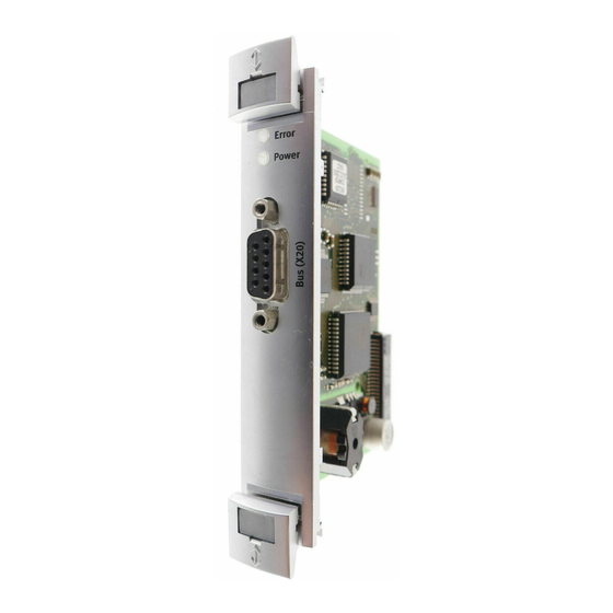
SPC200-COM-PDP Installation Belegung der Buchse der PROFIBUS-DP-Schnittstelle (X20) Pin 1 Pin 6 Pin 5 Pin 9 Signal Beschreibung Erde direkte Verbindung zum Gehäuse n.c. nicht angeschlossen RxD/TxD-P Empfang-/Sende-Daten-P CNTR-P *) Repeater Steuersignal DGND Datenbezugspotential (M5V) Versorgungsspannung-Plus (P5V) n.c. nicht angeschlossen... - Page 7 SPC200-COM-PDP Kabelspezifikation Empfehlung: Setzen Sie ein Kabel gemäß den Kabelspezifikati- on nach EN 50170 Teil 2 ein (Leitung A). - Wellenwiderstand: 135-165 Ohm (3-20 MHz) - Kapazitätsbelag: < 30 pF/m - Schleifenwiderstand: < 110 Ohm/km - Aderquerschnitt: > 0,34 mm Verwenden Sie spezielle Busanschlußstecker für PROFIBUS,...
- Page 8 SPC200-COM-PDP Inbetriebnahmehinweise Einstellen der PROFIBUS-Adresse Die PROFIBUS-Adresse (DP-Slave-Adresse) des SPC200 kön- nen Sie mit dem Software-Paket WinPISA oder dem Bedienfeld einstellen. Eine Änderung durch einen DP-Master ist nicht mög- lich. Anzahl der konfigurierbaren Ein - und Ausgänge Der SPC200 kommuniziert mit dem PROFIBUS-Master über ein E/A-Feld (interne Ein-/Ausgänge).
- Page 9 SPC200-COM-PDP Diagnose Die folgenden zwei Leuchtdioden (LEDs) auf der Feldbusbau- gruppe ermöglichen eine Schnell-Diagnose über den Be- triebszustand vor Ort: – POWER-LED (grün) – ERROR-LED (rot). POWER-LED ERROR-LED Betriebszustand (grün) (rot) ist aus ist aus Betriebsspannung fehlt leuchtet ist aus Betriebszustand normal, Verbindung zum Feldbusmaster vorhanden.
-
Page 10: Technische Daten
SPC200-COM-PDP Technische Daten SPC200-COM-PDP Temperaturbereich: - Betrieb C ... + 50 - Lagerung/Transport C ... + 70 Gewicht 80 g Relative Luftfeuchtigkeit 95 % nicht kondensierend Feldbus - Ausführung RS 485, potentialfrei - Übertragungsart seriell asynchron, halb-duplex - Protokolle PROFIBUS-DP (Norm-Slave) zertifiziert nach DIN 19245, Teil 1 bis 4;... - Page 11 SPC200-COM-PDP User instructions Field bus module type SPC200-COM-PDP has been designed for interfacing the SPC200 to the PROFIBUS-DP (as per EN 50170 part 2). With this field bus module the SPC200 can be operated as a slave on the PROFIBUS-DP.
- Page 12 SPC200-COM-PDP Fitting and removing the modules CAUTION Modules can be damaged by incorrect handling. • Do not touch any of the components. • Observe the regulations for handling components which are affected by electrostatic charges. • Discharge yourself electrostatically before fitting or removing modules, in order to protect the components against discharges of static electricity.
- Page 13 SPC200-COM-PDP Fitting the modules 1. Switch off the compressed air supply and the operating volt- age. 2. Unlock the safety lever (if fitted) and remove the blind plate. 3. Grasp the module by the front plate and push it into the guide rail.
- Page 14 SPC200-COM-PDP Installation Pin assignment of the PROFIBUS-DP interface (X20) Pin 1 Pin 6 Pin 5 Pin 9 Signal Description Earth/ground Direct connection to housing n.c. Not connected RxD/TxD-P Receive/send data - positive CNTR-P *) Repeater control signal DGND Data reference potential (M5V) Supply voltage - positive (P5V) n.c.
- Page 15 SPC200-COM-PDP Cable specification Recommendation: Use a cable in accordance with cable specifi- cation as per EN 50170 part 2 (cable A). - surge impedance: 135-165 Ohm (3-20 MHz) - capacitance per unit length: < 30 pF/m - loop resistance: < 110 Ohm/km - cross-sectional area: >...
-
Page 16: Commissioning Instructions
SPC200-COM-PDP Commissioning instructions Setting the PROFIBUS address You can set the PROFIBUS address (DP slave address) of the SPC200 with the software package WinPISA or with the opera- ting panel. Modification by a DP master is not possible. Number of configurable inputs and outputs The SPC200 communicates with the PROFIBUS master via an I/O field (internal inputs/outputs). - Page 17 SPC200-COM-PDP Diagnosis The two following LEDs on the field bus module enable the user to make a quick on-the-spot diagnosis of the operating status: – POWER LED (green) – ERROR LED (red). POWER LED ERROR LED Operating status (green) (red)
-
Page 18: Technical Specifications
SPC200-COM-PDP Technical specifications Type SPC200-COM-PDP Temperature range: - operation C ... + 50 - storage/transport C ... + 70 Weight 80 g Relative humidity 95 % non condensing Field bus - design RS 485, floating - transmission type serial asynchronous, half-duplex...
Need help?
Do you have a question about the SPC200-COM-PDP and is the answer not in the manual?
Questions and answers