Table of Contents
Advertisement
Advertisement
Table of Contents

Related Manuals for Manusa VECTOR

Summary of Contents for Manusa VECTOR
- Page 1 Installation Manual VECTOR Operator...
-
Page 2: Table Of Contents
2.2 Transport Conditions 6.2.3 Program Switch Connector 2.3 Storage Conditions 6.2.4 External Peripherals Connectors (15 VDC) 3. TECHNICAL DATA 6.2.5 Double Vector Connection and Use 3.1 General Dimensions 6.2.6 Interlocking Connection and Use 3.2 Technical Specifications 6.2.7 Connection to a PC 3.3 Low Energy... -
Page 3: Product Identification
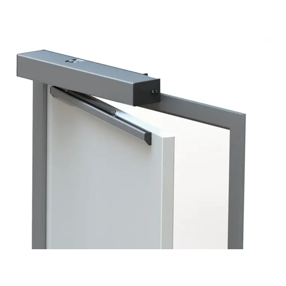
Bi-parting + Push arm VECTOR is an advanced electromechanical operator used for the automation of any type of new or existing swing door. It is a highly-efficient, high-performance operator, especially designed for intensive use, as it can automate both light and very heavy doors. - Page 4 D00619EN - v0 SWING OPERATOR - INSTALLATION MANUAL VECTOR Swing Operator 10 11 13 14 9. Navigation buttons 1. Blind side cover 10. Operator control display 2. Cover screws 11. Transformer 3. Main chassis profile 12. Installation screws 4. Re-send mechanism 5.
-
Page 5: Symbol Description
D00619EN - v0 SWING OPERATOR - INSTALLATION MANUAL 1.2 Symbol Description The symbols that appear in this manual and/or in the machine are listed below: ELECTRICAL HAZARD. The inside of the machine must IMPORTANT WARNING. Strictly adhere to the not be manipulated unless it has been previously indications provided with this symbol. -
Page 6: Product Ec Marking
D00619EN - v0 SWING OPERATOR - INSTALLATION MANUAL 1.4 Product EC Marking La máquina debe disponer de una etiqueta de marcado similar a la de la imagen. De no ser así, informar de la incidencia al Servicio Asistencia Técnica (ver dorso del manual). 1.5 Noise Statement The weighted acoustic pressure level of emissions A is below 70 dB. -
Page 7: Machine Delivery Conditions
D00619EN - v0 SWING OPERATOR - INSTALLATION MANUAL OTHER - Intermediate cover kit - Cover to measure 2 TRANSPORT, STORAGE AND MAINTENANCE CARACTERÍSTICAS MECÁNICAS 2.1 Machine Delivery Conditions is in charge of the initial delivery of the machine. Please make sure that all the parts and components arrive in good condition: that they have not been tampered with, that there is no item missing from the list on the delivery note, that it did not get wet or suffer from damage caused by the environment. -
Page 8: Technical Specifications
D00619EN - v0 SWING OPERATOR - INSTALLATION MANUAL 3.2 Technical Specifications manusa VECTOR swing operator offers high-end kinematic performance in the industry: MECHANICAL FEATURES 89x130x675mm (1 leaf) 89x130x2800mm (Fig.1) Dimensions (Height x Width x Length) (max. 2 leaves) Maximum leaf weight 250 Kg (See fig.2) -
Page 9: Low Energy
The installer should check the Low-Energy installation conformity with applicable standards. Protection of the closing edge should be evaluated individually. 3.4 Operation manusa doors are designed to operate automatically. Manual operation is only intended in the case of an emergency and to carry out cleaning, maintenance and adjustment tasks. -
Page 10: Decommissioning, Dismantling And Removal
Proceed to dismantle the unit removing the different elements, and discard and recycle waste accordingly. 3.7 Intended Use and Uses that Should be Avoided The intended use for the VECTOR operator is to automate swing doors designed for pedestrian access. Prohibited uses that should be avoided are listed below: •... -
Page 11: Pre-Installation
• Know the reference and application standards for products and services. 4.2 Physical and Environmental Requirements The VECTOR swing operator should be installed in places that meet the following requirements: • Smooth, flat, level floor. • Smooth, flat, level wall with sufficient load capacity. Capable of anchoring a suitable frame. -
Page 12: Electrical Pre-Installation Requirements
D00619EN - v0 SWING OPERATOR - INSTALLATION MANUAL 4.3 Electrical Pre-Installation Requirements Assembling a automatic door requires an electrical pre-installation with a 6A double-pole magneto-thermal switch, and it must comply with the cable sections specified below: The diagram shows the standard wiring for the elements that the operator includes as standard. Current Input: - 16mm corrugated tube. -
Page 13: Installation
D00619EN - v0 SWING OPERATOR - INSTALLATION MANUAL 5 INSTALLATION 5.1 Type of Arm that Can Be Installed • RIGID ARM: (Used when the operator is installed on the same side that the door opens). • STANDARD ARTICULATED ARM: The standard articulated arm can be mounted to PUSH. (It is used when the operator is installed on the opposite side from where the door opens). -
Page 14: Positioning Levels For The Fixing Holes
D00619EN - v0 SWING OPERATOR - INSTALLATION MANUAL 5.3 Positioning Levels for the Fixing Holes Make suitable holes for the type of fixing screw to be used, only after checking the ‘Positioning Levels’ indicated in the sections corresponding to the type of arm used. In the case of a double operator, prepare the connections (cable routes) between the two individual operators. - Page 15 D00619EN - v0 SWING OPERATOR - INSTALLATION MANUAL Fig. 4. Fig. 5.
- Page 16 D00619EN - v0 SWING OPERATOR - INSTALLATION MANUAL Fig. 6. Fig. 7.
- Page 17 D00619EN - v0 SWING OPERATOR - INSTALLATION MANUAL Fig. 8. Fig. 9. Fig. 10.
-
Page 18: Installing The Pushing Articulated Arm
D00619EN - v0 SWING OPERATOR - INSTALLATION MANUAL Before tightening the arm connection to the operator axis, check that the distance between the guide and the upper side of the arm is about 17mm. WARNING: After installing the rigid arm and the guide, ALWAYS check that the Switch position is to the right, as shown in Fig. - Page 19 D00619EN - v0 SWING OPERATOR - INSTALLATION MANUAL Fig. 12. Fig. 13.
- Page 20 D00619EN - v0 SWING OPERATOR - INSTALLATION MANUAL Fig. 14. Fig. 15. Fig. 16.
- Page 21 D00619EN - v0 SWING OPERATOR - INSTALLATION MANUAL WARNING: Attach the door’s leaf-joining point to the arm correctly, using reinforcements where necessary. • Turn the nut (Fig. 8 part A) to preload the spring, until the plate ends (Fig. 8 part. B) coincide with the line indicating the start point of the EN4 range (level L=0).
-
Page 22: Spring Adjustment
D00619EN - v0 SWING OPERATOR - INSTALLATION MANUAL 5.6 Spring Adjustment The strength of the spring should be adjusted according to the leaf width, and taking into account standard EN 1154 within the range EN 4 to EN 6. The adjustment range can be seen in the graph curve in Fig. 18, depending on the weight and width of the swing leaf, and regardless of the type of arm installed. -
Page 23: Connecting To The Power Supply
D00619EN - v0 SWING OPERATOR - INSTALLATION MANUAL 5.9 Connecting to the Power Supply WARNING: All the connection operations on the card terminal plates or the peripheral devices should be made with the power disconnected to avoid irreversible electrical damage. WARNING: Before continuing further operations, ensure that it is disconnected from the mains. -
Page 24: Vector Electronic Card
D00619EN - v0 SWING OPERATOR - INSTALLATION MANUAL 5.10 VECTOR Electronic Card Fig. 22 shows the main components of the electronic card: A - Jumper to display viewing I - Controls/inputs connectors B - Display and buttons J - Power supply for the sensors/accessories... -
Page 25: Arm-Type Selection
D00619EN - v0 SWING OPERATOR - INSTALLATION MANUAL 5.12 Arm-Type Selection Rigid arm (Left or right-opening leaf) → Configure the right program switch as shown in Fig. 11. Articulated arm (Left and right-opening leaf) → Configure the left program switch as shown in Fig. 11. 5.13 Connecting the Controls/Inputs SIGNAL DEFAULT... -
Page 26: Connector To Auxiliary Outputs
D00619EN - v0 SWING OPERATOR - INSTALLATION MANUAL When the contact is closed, the door enters stand-by mode (unlocked 7 - Stand-by state and deactivated). This logic setting only operates with the door in the closed position. 8 - Activate again from When the contact is closed, the door activates again after being in Stand-by stand-by. -
Page 27: Installing And Acquiring The Sensors
D00619EN - v0 SWING OPERATOR - INSTALLATION MANUAL 5.15 Installing and Acquiring the Sensors CARACTERÍSTICAS MECÁNICAS The operator is prepared to manage: • Safety sensors (see Fig. 21 A and B): they are mounted on the leaf and control the nearby area to detect possible obstacles, and stop movement or invert it to prevent blows, crushing or other sources of danger;... - Page 28 WARNING: The automatic acquisition procedure of supervised sensors should be repeated every time the configuration of the sensors connected to the operator is changed. WARNING: In the case of the Double Vector (2 leaves) operator, THE AUTOMATIC ACQUISITION PROCEDURE OF SUPERVISED SENSORS SHOULD BE CARRIED OUT ON BOTH ELECTRONIC CARDS (MASTER AND SLAVE).
-
Page 29: Dip-Switch Management
D00619EN - v0 SWING OPERATOR - INSTALLATION MANUAL 5.16 Dip-Switch Management CARACTERÍSTICAS MECÁNICAS There is a dip-switch on the electronic card with 8 positions for configuring the functionality and ON-OFF type basic operations. These settings are detected and memorised after a reset, and the possible dip-switch variations during operation are not taken into account: PARAMETER VALUE... - Page 30 D00619EN - v0 SWING OPERATOR - INSTALLATION MANUAL DESCRIPTION SETTINGS DEFAULT Return closing speed with spring RANGE: 1 ÷ 9 (VECTORM) (1 = minimum speed, 9 = maximum speed) Wind protection function with the RANGE: 0 ÷ 9 door closed (VECTORM) (0 = wind protection deactivated, 9 = maximum wind protection) RANGE: 1 ÷...
- Page 31 D00619EN - v0 SWING OPERATOR - INSTALLATION MANUAL DESCRIPTION SETTING DEFAULT 0 = Multimaster not managed MultiMaster address 1÷ 15 = Unique address for MultiMaster connections Angle of safety sensor exclusion during opening Exclusion of opening safety RANGE: 0 ÷ 40% of the entire course RANGE: 0 ÷...
-
Page 32: Commissioning
D00619EN - v0 SWING OPERATOR - INSTALLATION MANUAL WARNING: During the parameters modification phase, all motor movements will be disabled. When not using programming, the [ENT] key is an opening control (only for logic settings One Radar or two Radars). 5.17 Fig. -
Page 33: Management And Use
D00619EN - v0 SWING OPERATOR - INSTALLATION MANUAL 6.2 Management and Use CARACTERÍSTICAS MECÁNICAS 6.2.1 Operational Logic Settings LOGIC SETTING DESCRIPTION In all operating modes (excluding Stop Closed) a motorised reduced -speed opening (velocity Low Energy) and an augmented stop period (disabled per- sons stop time) can be achieved using the disabled persons opening con- LOW-ENERGY trols (in the configuration input [AUX IN 1 configuring the parameter 15=0,... -
Page 34: Management Of Electronic Locks
D00619EN - v0 SWING OPERATOR - INSTALLATION MANUAL 6.2.2 Management of Electronic Locks DESCRIPTION SETTING DEFAULT 0 = 12 VDC Electronic lock control voltage 1 = 24 VDC 0 = Not used 1 = Electronic lock with mechanical reset when closed again 2 = Electromagnetic (maglock) (24VDC only) Types of electronic lock 3 = Electronic lock... - Page 35 D00619EN - v0 SWING OPERATOR - INSTALLATION MANUAL VALUE OPERATION TYPE See Fig. 32 - Electronic lock which, when powered, frees the leaf to move. ELECTRONIC It resets by cutting power to the lock when the leaf opens more than 10°. LOCK WITH AU- It requires a door jolt freeing device in order to make it easier to unlock RANGE: 0÷9...
-
Page 36: Program Switch Connector
6.2.5 Double Vector Connection and Use The Double VECTOR is a connection between two operators for a double swing leaf. It can be connected in two ways: 1. With two individual VECTORs, each installed in one leaf, but making the connection between the two;... - Page 37 D00619EN - v0 SWING OPERATOR - INSTALLATION MANUAL To install the Double VECTOR with two individual Vectors, follow the steps below: 1. Disassemble all of the components attached to the bases of each operator. 2. Attach the bases of each operator to the wall making the necessary holes for each type of screw used in mounting the operator;...
- Page 38 D00619EN - v0 SWING OPERATOR - INSTALLATION MANUAL 2. For double leaf with a central stop, it is necessary to configure a delay in the movement of the leaves. During opening, normally a lesser delay is sufficient, mainly for ‘aesthetic’ reasons (as a maximum, one leaf ‘pushes’...
-
Page 39: Interlocking Connection And Use
6.2.6 Interlocking Connection and Use The VECTOR operator central control is set to be able to operate in interlocking mode through a connection to an electronic central control of the same class. With the interlocking function, the opening of a door can be done independently, if the other is not moving, that is, if it is not in a movement phase. -
Page 40: Safety
D00619EN - v0 SWING OPERATOR - INSTALLATION MANUAL 7 SAFETY 7.1 General Safety Instructions • Before performing any type of task on the machine, the work area must be checked : • Keep the area clean and tidy. • Ensure there is sufficient light. •... - Page 41 D00619EN - v0 SWING OPERATOR - INSTALLATION MANUAL 7.4 Risk Assessment Below, there is an outline of the different hazardous situations that may arise with our machines after leaving the factory, either during the installation process, commissioning, maintenance, adjustment or disassembly. There is also reference to the risk minimisation measures that must be taken during the aforementioned phases of the machine’s life: MECHANICAL HAZARDS Risk...
-
Page 42: Safety Regulations
In the majority of cases, to resume door operation it will be enough to select the door open mode and then the automatic door mode. If after this operation the anomaly persists, it will be necessary to resort to a manusa authorised service technician. -
Page 43: Appendixes
SWING OPERATOR - INSTALLATION MANUAL 10 APPENDIXES CARACTERÍSTICAS MECÁNICAS 10.1 CE Declaration of Conformity CARACTERÍSTICAS MECÁNICAS DECLARATION OF CONFORMITY Manufacturer: MANUSA DOOR SYSTEMS Address: Av. Vía Augusta, 85-87, 6ª planta 08174 – Sant Cugat del Vallès Barcelona, Spain 902 321 400 902 321 450 www.manusa.com... -
Page 44: Installation Checklist
D00619EN - v0 SWING OPERATOR - INSTALLATION MANUAL 10.2 Installation Checklist Compliance with safety requirements is a primary manusa objective for , given that hundreds of thou- sands of people in more than 70 countries pass through our doors daily. -
Page 45: Maintenance Book
D00619EN - v0 SWING OPERATOR - INSTALLATION MANUAL 10.3 Maintenance Book CARACTERÍSTICAS MECÁNICAS 10.3.1 Action Frequency Frequency for swing doors: 12 months Without power (neither electric nor batteries, if present) Clean and grease turning pieces, hinges, etc. Check the strength of support points Adjust screws With power Check the correct operation of the safety elements... -
Page 46: Actions Log
SWING OPERATOR - INSTALLATION MANUAL 10.3.2 Actions Log Date …… / ..… / .…... PSV No.……………………… Date …… / ..… / .…... PSV No.……………………… Signed Manusa Signed Customer Signed Manusa Signed Customer Date …… / ..… / .…... PSV No.………………………... -
Page 47: Notes
D00619EN - v0 SWING OPERATOR - INSTALLATION MANUAL 10.4 Notes CARACTERÍSTICAS MECÁNICAS... - Page 48 HEAD OFFICE Av. Vía Augusta, 85-87, 6ª 08174 Sant Cugat del Vallés Barcelona - Spain The characteristics detailed in this document are for information only and do not represent any contractual Tel. +34 902 321 400 obligation. The manufacturer reserves the right to make modifications without prior warning Fax +34 902 321 450...
Need help?
Do you have a question about the VECTOR and is the answer not in the manual?
Questions and answers