Table of Contents
Advertisement
Tel +1 (717) 767-6511
Fax +1 (717) 764-0839
www.redlion-controls.com
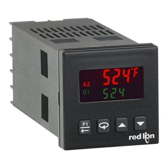
MODELS T16 & P16 - TEMPERATURE/PROCESS CONTROLLERS
FAX/WEB
DOC #
05019
DIMENSIONS In inches (mm)
EMC
NEMA 4X
COMPLIANT
IP65
Product F
eatures
Product F
eatures
GENERAL DESCRIPTION
The Model T16 Controller accepts signals from a variety of
temperature sensors (thermocouple or RTD), while the Model
P16 Controller accepts either a 0 to 10 VDC or 0/4 to 20 mA DC
input signal. Both controllers can provide an accurate output
control signal (time proportional or DC Analog Output) to
maintain a process at a setpoint value. Dual 4-digit displays allow
viewing of the process/temperature and setpoint simultaneously.
Front panel indicators inform the operator of the controller and
output status. The comprehensive programming allows these
controllers to meet a wide variety of application requirements.
MAIN CONTROL
The controller operates in the PID Control Mode for both
heating and cooling, with on-demand auto-tune, that establishes
the tuning constants. The PID tuning constants may be fine-
tuned through the front panel and then locked out from further
modification. The controller employs a unique overshoot
suppression feature, that allows the quickest response without
excessive overshoot. Switching to Manual Mode provides the
operator direct control of the output. The controller may also be
programmed to operate in On/Off mode with adjustable
hysteresis.
ALARMS
Optional alarm(s) can be configured independently for
absolute high or low acting with balanced or unbalanced
hysteresis. They can also be configured for deviation and band
alarm. In these modes, the alarm trigger values track the setpoint
value. Adjustable alarm trip delays can be used for delaying
!
!
!
!
!
!
!
!
PROGRAMMING
FRONT PANEL
PARAMETER
SOFTWARE
PROGRAMMABLE
LOCKOUT
output response. The alarms can be programmed for Automatic
or Latching operation. A selectable standby feature suppresses
the alarm during power-up until the temperature stabilizes
outside the alarm region.
ANALOG OUTPUT OPTION
configured and scaled for control or re-transmission purposes.
The programmable output update time reduces valve or actuator
activity.
PC PROGRAMMING KIT
9 pin RS232 connector, cable and Windows
configuration software. The software allows downloading,
uploading and storage of T16 and P16 program files. All
controllers have a communications port that allows configuration
by PC even without controller power connected. Controller
calibration is also possible using the software when the proper
calibration equipment and controller power is connected.
CONSTRUCTION
black plastic textured case and bezel with a clear display window.
The front panel meets NEMA 4X/IP65 specifications when
properly installed. In applications that do not require protection to
NEMA 4X, multiple controllers can be stacked horizontally or
vertically. Modern surface-mount technology, extensive testing,
plus high immunity to noise interference makes the controller
extremely reliable in industrial environments.
1
PID CONTROL WITH REDUCED OVERSHOOT
T16 ACCEPTS TC AND RTD
P16 ACCEPTS 0-10 V AND 0/4-20 mA SIGNALS
ON DEMAND AUTO-TUNING OF PID SETTINGS
DC ANALOG OUTPUT (OPTIONAL)
USER PROGRAMMABLE FUNCTION BUTTON
PC OR FRONT PANEL PROGRAMMING
PC CONFIGURABLE WITH TP16KIT
UL Recognized Component,
File #E156876
y
ALARMS
ANALOG
OUTPUT
The optional DC Analog Output (10 V or 20 mA) can be
The optional TP16KIT contains a programming module with a
The controller is constructed of a lightweight, high impact,
Bulletin No. T&P16-E
Drawing No. LP0486
Released 12/02
x
PC
CONFIGURABLE
®
based
PANEL CUT-OUT
Advertisement
Table of Contents

Related Manuals for red lion T16


Summary of Contents for red lion T16
- Page 1 GENERAL DESCRIPTION output response. The alarms can be programmed for Automatic FAX/WEB or Latching operation. A selectable standby feature suppresses The Model T16 Controller accepts signals from a variety of DOC # 05019 the alarm during power-up until the temperature stabilizes temperature sensors (thermocouple or RTD), while the Model outside the alarm region.
-
Page 2: Safety Summary
10 V/m: !%#%#$ - Measurement exceeds - sensor range Measurement input signal may deviate during EMI !"&'($ - Open sensor is detected (T16 only) disturbance. !)*+,$ - Shorted sensor is detected (RTD only) For operation without loss of performance: !)'()$... -
Page 3: Input Specifications
Ohms Linear Resistance Input Impedance: 20 MΩ for all types Lead Resistance Effect: 0.25 µV/Ω 4. TEMPERATURE INDICATION ACCURACY: (T16 only) Cold Junction Compensation: Less than ±1°C typical (1.5°C ± (0.3% of span, +1°C) at 23 °C ambient after 20 minute warm max) error over ambient temperature range. -
Page 4: Ordering Information
Ordering Information Ordering Information PART NUMBERS MODEL NO. MAIN CONTROL 2 ALARMS & USER INPUT 18-36 VDC/24 VAC 85 to 250 VAC Relay — T1610010 T1610000 Relay T1611110 T1611100 Logic/SSR — T1620010 T1620000 Logic/SSR T1621110 T1621100 Analog Out * T1641110 T1641100 Relay —... -
Page 5: Emc Installation Guidelines
2. Use shielded (screened) cables for all Signal and Control inputs. Ferrite Suppression Cores for Signal and Control cables: The shield (screen) pigtail connection should be made as short Fair-Rite # 0443167251 (Red Lion Controls # FCOR0000) as possible. The connection point for the shield depends TDK # ZCAT3035-1330A somewhat upon the application. -
Page 6: Step 2 Installing The Controller
STEP 2 INSTALLING THE CONTROLLER The T16 and P16 controllers meet NEMA 4X/IP65 requirements for indoor use to provide a watertight seal in steel panels with a minimum thickness of 0.09", or aluminum panels with a minimum thickness of 0.12". The controllers are designed to be mounted into an enclosed panel. -
Page 7: Step 3 Wiring The Controller
STEP 3 WIRING THE CONTROLLER WIRING CONNECTIONS All wiring connections are made to the rear screw terminals. When wiring the controller, use the numbers on the label and those embossed on the back of the case, to identify the position number with the proper function. All conductors should meet voltage and current ratings for each terminal. -
Page 8: Step 4 Reviewing The Front Keys And Display
STEP 4 REVIEWING THE FRONT KEYS AND DISPLAY FRONT PANEL KEYS The Arrow keys are used to scroll through The F1 key is pressed to exit (or escape) directly to the parameter selections/values and in the Configuration start of the Display Loop. While in the Display Loop, the F1 Loop they are used to scroll to the appropriate key can be pressed to activate its programmed function. - Page 9 The values shown for the displays are the factory settings. SETPOINT VALUE (SP1) * INTEGRAL TIME " )& 12,, 5555 seconds .555 5555 67 6 Integral action shifts the center point position of the proportional band to eliminate error in the steady state. The higher the integral time, the slower the response.
- Page 10 Control Mode Explanations. The setpoint ramp rate can reduce sudden shock to the process and reduce overshoot on startup or after setpoint changes, by ramping the setpoint at a controlled rate. R annunciator flashes while ramping. With the T16, the ramp rate...
- Page 11 AUTO-TUNE START ACCESS CODE " " ,%(' 4;-' (" .08= (" The Auto-Tune procedure of the controller sets the If the Access Code is set from -1 to -125, in Lockout Module Proportional Band, Integral Time, Derivative Time, Digital Filter, , Access Code will appear here.
- Page 12 STEP 7.1 MODULE 1 - Input Parameters ( ) T16 Only 0.1( PARAMETER MENU INPUT TYPE SETPOINT LOW LIMIT ,?&' )&#" SELECTION TYPE SELECTION TYPE .555 5555 tc-t tc-N T TC N TC ,@.A tc-E tc-C E TC C TC...
- Page 13 F1 KEY FUNCTION The controller performs the selected F1 Key Function, when ! is pressed while in the Display Loop. In any other loop or /012 module location, pressing ! will perform an escape to the Display Loop. ("(' No Function: No function is performed. Auto/Manual Select: This function toggles (momentary action) the controller between Automatic and Manual Control.
- Page 14 DISPLAY VALUE SCALING POINT 2 USER INPUT FUNCTION (OPTIONAL) -)&8 12&, .555 5555 0667 6 &#"4 Enter the second coordinate Display Value by using the arrow SELECTION FUNCTION SELECTION FUNCTION keys. NONE No Function Setpoint 1 or 2 Select PLOC SPrP Program Lock Setpoint Ramp Disable...
- Page 15 STEP 7.2 MODULE 2 - Output Parameters ( 8."& PARAMETER MENU SENSOR FAIL POWER LEVEL CYCLE TIME "&/# 4?4, percent O1 seconds 67 6 8=67 6 .066 percent O1/O2 87 6 This parameter sets the power level for the control outputs in The Cycle Time is entered in seconds with one tenth of a the event of a sensor failure.
- Page 16 ANALOG OUTPUT RANGE (OPTIONAL) ANALOG LOW SCALING (OPTIONAL) :(,& :(#" 6.06 6.86 .555 5555 <.86 <.86 67 6 Select the type of output and range. The Analog output The Analog Output assignment value that corresponds to 0 V, jumpers are factory set to current. They must be changed if 0 mA or 4 mA output as selected.
- Page 17 STEP 7.4 MODULE 4 - Alarm Parameters ( ) (OPTIONAL) <.:# PARAMETER MENU AVAILABLE ALARM ACTIONS No action, the remaining Alarm Alarm 1 and 2 value tracks the NONE d-HI None Deviation High parameters are not available. Setpoint value Alarm 1 and 2 value tracks the The alarm energizes when the Process d-LO Deviation Low...
- Page 18 ALARM ACTION ALARM 2 ALARM ACTION ALARM 1 :4,8 :4,0 NONE AbHI AbLO AuHI AuLO NONE AbHI AbLO AuHI AuLO :>*1 :>*1 d-HI d-LO b-IN b-ot CooL d-HI d-LO b-IN b-ot HEAt Select the action for the alarms. See Alarm Action Figures for Select the action for the alarms.
- Page 19 STEP 7.5 MODULE 5 - Cooling (Secondary) Parameters ( =."8 PARAMETER MENU To enable Cooling in Heat/Cool applications, the Alarm 2 Action must first be set for Cooling. (For P16 Controllers, the cooling output is sometimes referred to as secondary output.) When set to cooling, the output no longer operates as an alarm but operates as a cooling output.
- Page 20 They should be shielded from air movement [CAL] Press ". and allowed sufficient time to equalize in temperature. (As an alternative, the T16 thermocouple may be placed in a calibration [CJC] Press ". (T16 only) bath of known temperature.) If performing the millivolt calibration...
-
Page 21: Troubleshooting
2. Perform cold junction calibration. 3. Loss of setup parameters. 3. Check setup parameters. 4. Internal malfunction. 4. Perform Input calibration. "&'( IN DISPLAY (T16) 1. Probe disconnected. 1. Connect probe. 2. Broken or burned-out probe. 2. Replace probe. 3. Corroded or broken terminations. -
Page 22: Control Mode Explanations
CONTROL MODE EXPLANATIONS ON/OFF CONTROL ON/OFF CONTROL - HEAT/COOL OUTPUT FIGURES The controller operates in On/Off Control when the Proportional Band is set to 0.0%. In this control mode, the process will constantly oscillate around the setpoint value. The On/Off Control Hysteresis (balanced around the setpoint) can be used to eliminate output chatter. -
Page 23: Pid Tuning Explanations
TIME PROPORTIONAL PID CONTROL MANUAL CONTROL MODE In Time Proportional applications, the output power is converted into In Manual Control Mode, the controller operates as an open loop output On time using the Cycle Time. For example, with a four second system (does not use the setpoint and process feedback). -
Page 24: Manual Tuning
) to 10.0% for temperature the Hidden Loop. If the process will not stabilize and starts to models (T16) and 100.0% for process models (P16). oscillate, set the Proportional Band two times higher and go 2. Set both the Integral Time (... - Page 25 -1)& OUTPUT POWER ACCESS tUNE (" AUTO-TUNE START HIdE PID VALUE ACCESS HIdE ALARM VALUE ACCESS CodE 0.1( INPUT MODULE ( ) T16 ONLY ACCESS CODE SPSL #"4 SETPOINT SELECT ACCESS DISPLAY PARAMETER FACTORY SETTING USER SETTING SPrP *1-' tYPE...
- Page 26 T16 & P16 PROGRAMMING QUICK OVERVIEW...
- Page 27 This page intentionally left blank.
-
Page 28: Limited Warranty
The Company disclaims all liability for any affirmation, promise or representation with respect to the products. The customer agrees to hold Red Lion Controls harmless from, defend, and indemnify RLC against damages, claims, and expenses arising out of subsequent sales of RLC products or products...
Need help?
Do you have a question about the T16 and is the answer not in the manual?
Questions and answers