Advertisement
Table of Contents
- 1 Table of Contents
- 2 General Specifications
- 3 Ordering Information
- 4 EMC Installation Guidelines
- 5 Setting the Current Input Jumper
- 6 Installing the Controller
- 7 Wiring the Controller
- 8 Reviewing the Front Keys and Display
- 9 Programming Loops
- 10 Troubleshooting
- 11 Control Mode Explanations
- 12 PID Tuning Explanations
- 13 Parameter Value Chart
- 14 Programming Overview
- Download this manual
MODEL PXU - TEMPERATURE/PROCESS CONTROLLERS
U L
C
US LISTED
R
13RW
PROCESS CONTROL EQUIPMENT
GENERAL DESCRIPTION
The PXU controller accepts signals from a variety of temperature sensors
including thermocouple or RTD. The controller can also be configured for
process inputs including 0 to 5/10 VDC, 0/4 to 20 mA DC, or 0 to 50 mV DC.
The PXU can provide an accurate output control signal (time proportional or DC
Analog Output) to maintain a process at a determined setpoint value. Dual
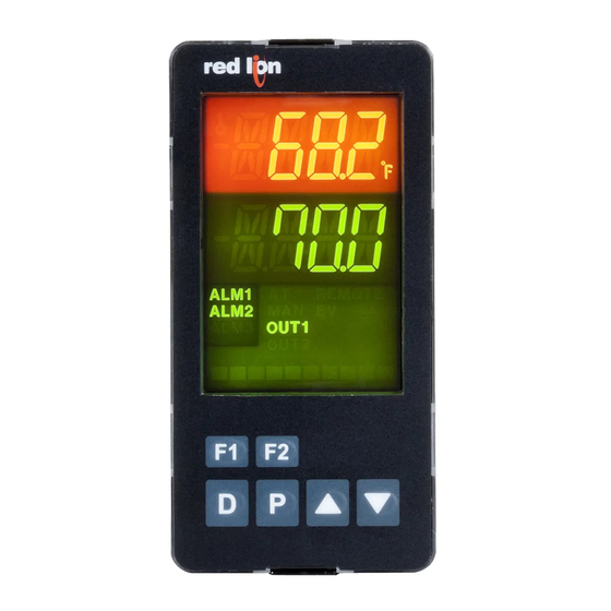
4-digit display readings allow viewing of the temperature/process and setpoint
value simultaneously. Front panel indicators inform the operator of alarm and
control output status. Comprehensive programming features allow this controller
to meet a wide variety of application requirements.
MAIN CONTROL
The PXU allows the user to select between PID, On/Off and Manual control
mode. The PXU has the ability to provide 2 control outputs. The control outputs
can be individually configured for Reverse or Direct (heating or cooling)
applications. The PID tuning constants can be established via on-demand auto-
tune. The PID constants can also be programmed, or fine-tuned, through the
front panel or a PC and then locked out from further modification.
ALARMS
Alarm(s) can be configured independently for absolute high or low acting
with balanced or unbalanced hysteresis. They can also be configured for
deviation and band alarm. In these modes, the alarm trigger values track the
setpoint value. Adjustable alarm hysteresis can be used for delaying output
response. The alarms can be programmed for Automatic or Latching operation.
A selectable standby feature suppresses the alarm during power-up until the
temperature stabilizes outside the alarm region.
CONSTRUCTION
DIMENSIONS In inches (mm) - 1/16 DIN
1.89
(48.0)
1.89
(48.0)
0.26
3.14 (79.70)
(6.70)
z PID CONTROL
z ACCEPTS TC and RTD
z ACCEPTS 0-10 V, 0/4-20 mA or 0-50 mV SIGNALS
z FUNCTIONS AS A DIGITAL POT
z ON DEMAND AUTO-TUNING OF PID SETTINGS
z DC ANALOG CONTROL OUTPUT (OPTIONAL)
z 2 USER PROGRAMMABLE FUNCTION BUTTONS
z PC (MODELS WITH RS 485) OR FRONT PANEL PROGRAMMING
z 1/16, 1/8 or 1/4 DIN
z CONTROLLERS MEET IP65 REQUIREMENTS
The PXU is constructed of a lightweight, high impact, black plastic textured
case with a clear display window. Modern surface-mount technology, extensive
testing, plus high immunity to noise interference makes the controller extremely
reliable in industrial environments.
SAFETY SUMMARY
All safety related regulations, local codes and instructions that appear in the
manual or on equipment must be observed to ensure personal safety and to
prevent damage to either the instrument or equipment connected to it. If
equipment is used in a manner not specified by the manufacturer, the protection
provided by the equipment may be impaired.
Do not use this unit to directly command motors, valves, or other actuators not
equipped with safeguards. To do so can be potentially harmful to persons or
equipment in the event of a fault to the controller. If redundant safeguards are not
in place, an independent and redundant temperature limit indicator with alarm
outputs is strongly recommended.
CAUTION: Risk of Danger.
Read complete instructions prior to
installation and operation of the unit.
CAUTION: Risk of electric shock.
When the power is on, DO NOT touch the AC terminals, an electric shock may
occur. Make sure the power is disconnected when you check the input power
supply.
1. Prevent dust or metallic debris from falling into the controller and causing malfunctions. DO
NOT modify the controller.
2. The PXU is an open-type device. Make sure it is installed in an enclosure free of dust and
humidity in case of an electric shock.
3. Wait for one minute after the power is switched off to allow the unit to discharge. DO NOT
touch the internal wiring within this period of time.
0.31
(7.80)
0.47 (11.88)
0.83 (21.0)
1
Bulletin No. PXU-D
Drawing No. LP0932
Released 09/15
PANEL CUT-OUT
1.77
(45.0)
1
7
2
8
13
14
1.77
3
9
15
(45.0)
16
4
10
17
18
5
11
6
12
Advertisement
Table of Contents

Related Manuals for red lion PXU


Summary of Contents for red lion PXU
- Page 1 1. Prevent dust or metallic debris from falling into the controller and causing malfunctions. DO NOT modify the controller. temperature stabilizes outside the alarm region. 2. The PXU is an open-type device. Make sure it is installed in an enclosure free of dust and CONSTRUCTION humidity in case of an electric shock.
-
Page 2: Table Of Contents
DIMENSIONS In inches (mm) - 1/8 DIN PANEL CUT-OUT 1.89 0.45 1.76 2.82 (71.5) (48.0) (11.4) (44.5) 3.77 3.60 3.60 (95.8) (91.5) (91.5) DIMENSIONS In inches (mm) - 1/4 DIN PANEL CUT-OUT 0.45 3.58 (91.0) 3.77 (95.8) 2.82 (71.5) (11.4) 3.58 3.58 (91.0) -
Page 3: General Specifications
GENERAL SPECIFICATIONS RTD INPUTS: Type: 2 or 3 wire 1. DISPLAY: LCD negative image transmissive with backlighting. Top Excitation: 180 µA typical (process) display with orange backlighting, bottom (parameter) display with Resolution: 1° or 0.1° for all types green backlighting. Line 1 and 2: 4 digits each line TYPE INPUT TYPE... -
Page 4: Ordering Information
10. ISOLATION LEVEL: 12. ENVIRONMENTAL CONDITIONS: AC power with respect to all other I/O: 250 V working (2300 V for 1 min.) Operating Temperature Range: 0 to 50°C Sensor input to analog output: 50 V working (500 V for 1 minute) Storage Temperature Range: -20 to 65°C Relay contacts to all other I/O: 250 V working (2300 V for 1 minute) Operating and Storage Humidity: 80% max relative humidity (non-... -
Page 5: Emc Installation Guidelines
Visit RLC’s web site at http://www.redlion.net/emi for more information on 4. Long cable runs are more susceptible to EMI pickup than short cable runs. EMI guidelines, Safety and CE issues as they relate to Red Lion Controls 5. In extremely high EMI environments, the use of external EMI suppression products. -
Page 6: Installing The Controller
2.0 i nsTalling The OnTrOller 1/16 DIN Installation The controller is designed to be mounted into an enclosed panel. The unit must be inserted in the case during installation of the controller. Instructions: 1. Prepare the panel cutout to the proper dimensions. 2. -
Page 7: Wiring The Controller
3.0 W iring The OnTrOller WIRING CONNECTIONS AC 100~240V All wiring connections are made to the rear screw terminals. 50/60 Hz RS-485 2 14 When wiring the controller, use the numbers on the label and those embossed on the back of the case, to identify the position 3 15 AL 1 number with the proper function. -
Page 8: Reviewing The Front Keys And Display
4.0 r evieWing The rOnT eys and isplay FRONT PANEL KEYS The Arrow keys are used to scroll through parameter selections/ In the Display Loop, the D key is pressed to identify the display values and in the Configuration Loop they are used to scroll to the parameter and to advance to the next enabled display item. - Page 9 DISPLAY LOOP At power up, all display segments light, and then the programmed input type MAIN and the controller’s software version will flash. Then the Temperature/Process Value is shown in the top display, and the bottom display will show the first DISPLAY LOOP Display Loop parameter configured as in Configuration Module 3.
- Page 10 . The Integration Default is the default integration value of integral control. When the process value enters the proportional band, the PXU will take the Integration Default as the default control output of integral control. The value is determined at Auto-Tune.
- Page 11 ALARM RESET AUTO CONTROL MODE s C OnOF I Select the desired control mode. When OnOF is selected, the PID parameters This parameter provides for the ability to individually reset active alarms are not available. from the front panel, without using 1 or 2 function keys.
- Page 12 7.1 mOdule 1 - i npuT arameTers 1-IN PARAMETER MENU CNFP 1-INP tYPE SCAL dCPt FLtr bANd SHFt dSP1 dSP2 SPLO SPHI FILTER INPUT TEMP DECIMAL DIGITAL SHIFT/ DISPLAY DISPLAY SETPOINT SETPOINT TYPE SCALE RESOLUTION FILTERING BAND OFFSET VALUE 1 VALUE 2 LOW LIMIT HIGH LIMIT...
- Page 13 SETPOINT HIGH LIMIT F KEY FUNCTION I I I input range dependent The controller has a programmable high setpoint limit value to restrict the The controller performs the selected F1 Key Function, when 1 is pressed. range of the setpoint.
- Page 14 7.2 mOdule 2 - O uTpuT arameTers 2-OP PARAMETER MENU 2-OP CNFP OPAC CtrL CYC1 OP1L OP1H 1F01 An1L An1H CYC2 OP2L CONTROL CONTROL OP1 CYCLE OUTPUT 1 OUTPUT 1 INPUT OUTPUT 1 OUTPUT 1 OP2 CYCLE OUTPUT 2 MODE ACTION TIME POWER...
- Page 15 RELATIVE GAIN OUTPUT 2 POWER LOWER LIMIT . . . . . . This parameter may be used to limit controller power at the lower end due to This defines the gain of relative to .
- Page 16 7.3 mOdule 3 - l OCKOuT arameTers 3-LC PARAMETER MENU 3-LC CNFP SPrP PId OPOF ProP Intt dErt dInt SETPOINT OUTPUT 1 OUTPUT 2 SETPOINT CONTROLLER OUTPUT PROPORTIONAL DERIVATIVE INTEGRATION INTEGRAL POWER POWER RAMP RATE GROUP STATUS POWER BAND TIME TIME DEFAULT OFFSET...
- Page 17 7.4 mOdule 4 - a ) (O larm arameTers pTiOnal 4-AL PARAMETER MENU 4-AL CNFP ACt1 Lit1 rSt1 Stb1 AL-1 1FA1 Act2 Lit2 rSt2 Stb2 AL-2 ALARM 1 ALARM 1 ALARM 1 ALARM 1 ALARM 1 INPUT FAIL ALARM 2 ALARM 2 ALARM 2 ALARM 2...
- Page 18 ALARM 1 ACTION ALARM 2 ANNUNCIATOR C Normal NONE AbHI AbLO AuHI AuLO Reverse v d-HI d-LO b-IN b-ot With normal selection, the alarm annunciator indicates an “on” alarm output Select the action for the alarm. See Alarm Action Figures at the beginning of 2.
- Page 19 INPUT FAIL ALARM 3 ACTION ALARM 3 RESET MODE 3 Automatic I3 Latched In Automatic mode, an energized alarm turns off automatically after the Select the Alarm action in the event of a detected input failure (open TC/RTD Temperature/Process value leaves the alarm region.
- Page 20 1. The PXU registers can be read as holding (4x) or input (3x) registers. 2. The PXU should not be powered down while parameters are being changed. Doing so may result in an in-complete write to the non-volatile memory and produce checksum errors.
-
Page 21: Troubleshooting
7.5 mOdule 9 f (9-FS) aCTOry erviCe peraTiOns 9-FS CNFP PARAMETER MENU CodE FACTORY SERVICE CODE RESTORE FACTORY SETTINGS C Press and hold B to display C . Press :. The controller will display and then return to C. Press = to return to the Display Loop. This will overwrite all user settings with Factory Settings. -
Page 22: Control Mode Explanations
OnTrOl xplanaTiOns ON/OFF CONTROL ON/OFF CONTROL - HEAT/COOL OUTPUT FIGURES In this control mode, the process will constantly oscillate around the setpoint INPUT (db2) = 0 DEADBAND/OVERLAP value. The On/Off Control Hysteresis (balanced around the setpoint) can be used to eliminate output chatter. Output Control Action can be set to reverse for SP + 1/2 CHYS heating (output on when below the setpoint) or direct for cooling (output on when above the setpoint) applications. -
Page 23: Pid Tuning Explanations
In Linear PID Control applications, OP1 provides a linear output signal that Output. The Low and High Output Power limits are ignored when the controller is proportional to the calculated OP1 value (% Output Power). The PXU allows is in Manual. - Page 24 9. Set the Derivative Time to 1/8 (0.125) of the Integral Time. DIGITAL POTENTIOMETER A PXU with an analog type Control Output 1 can be used as a digital potentiometer. To use the PXU as a digital pot, configure the PXU for Manual control mode.
-
Page 25: Parameter Value Chart
PARAMETER VALUE CHART Programmer:______________________Date:_________ Controller Number:_______ Security Code:_______ INPUT MODULE ( ALARM MODULE ( I 4 FACTORY FACTORY DISPLAY PARAMETER USER SETTING DISPLAY PARAMETER USER SETTING SETTING SETTING typE Input Type t-J ACt1 Alarm 1 Action NONE SCAL Temperature Scale °F Lit1 Alarm 1 Annunciator... -
Page 26: Programming Overview
vervieW... - Page 28 LIMITED WARRANTY (a) Red Lion Controls Inc., Sixnet Inc., N-Tron Corporation, or Blue Tree Wireless Data, Inc. (the “Company”) warrants that all Products shall be free from defects in material and workmanship under normal use for the period of time provided in “Statement of Warranty Periods” (available at www.redlion.net) current at the time of shipment of the Products (the “Warranty Period”).
- Page 29 1. The PXU registers can be read as holding (4x) or input (3x) registers. 2. The PXU should not be powered down while parameters are being changed. Doing so may result in an in-complete write to the non-volatile memory and produce checksum errors.
- Page 30 REGISTER FACTORY REGISTER NAME LOW LIMIT HIGH LIMIT ACCESS COMMENTS (4x) SETTING INPUT PARAMETERS 0 = tc-K 1 = tc-J 2 = tc-t 3 = tc-E 4 = tc-N 5 = tc-r 6 = tc-S 7 = tc-b 8 = tc-L 9 = tc-U Input Type Read/Write...
- Page 31 REGISTER FACTORY REGISTER NAME LOW LIMIT HIGH LIMIT ACCESS COMMENTS (4x) SETTING 1 = 1 Display unit; In combination Reverse(r) and Direct(d) modes, this defines the overlap area in -99(.9) or 999(.9)° or Deadband/Overlap Read/Write which both OP1 and OP2 are active -999 (process) 9999 (process) (negative value) or the deadband area (positive...
- Page 32 REGISTER FACTORY REGISTER NAME LOW LIMIT HIGH LIMIT ACCESS COMMENTS (4x) SETTING Input Fail Alarm 3 Action Read/Write 0 = Off; 1 = On 250(.0)° or 1 = 1 Display unit; The same value applies to all Alarm Hysteresis Read/Write 2500 (process) alarms.
Need help?
Do you have a question about the PXU and is the answer not in the manual?
Questions and answers