
Subscribe to Our Youtube Channel
Related Manuals for red lion PAX2C


Summary of Contents for red lion PAX2C
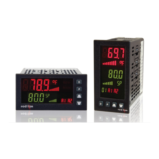
- Page 1 LP0890 User Manual PAX2C – 1/8 DIN Temperature/ Process PID Controller With FlexBus™ Phone: 800.894.0412 - Fax: 888.723.4773 - Web: www.the-red-lion.net - Email: info@the-red-lion.net...
- Page 2 SAFETY SUMMARY All safety related regulations, local codes and instructions that appear in this literature or on equipment must be observed to ensure personal safety and to prevent damage to either the instrument or equipment connected to it. If equipment is used in a manner not specified by the manufacturer, the protection provided by the equipment may be impaired.
-
Page 3: Table Of Contents
PAX2C Frequently Used Modbus Registers ........ -
Page 4: Ordering Information
Note: For Modbus communications use an RS485 Communications Output Card and configure communication (tYPE) parameter for Modbus. * This card is not suitable for use in older PAX2C models. For proper installation, 3 case knock-out features must be present on the top case surface (horizontal controller) or right case surface (vertical controller). -
Page 5: Using This Manual
- Plug the other end of the USB cable into an available USB port on the PC. - Apply power to the PAX2C. If a FlexCard has been removed, or has had the address changed, error message(s) will need to be resolved before continuing. -
Page 6: General Controller Specifications
eneral OnTrOller PeCifiCaTiOns 1. DISPLAY: Negative image LCD with tri-color backlight. Temperature Inputs: The display is divided into seven independently programmable color zones: Scale: °F or °C Line 1, Line 2, Universal Annunciators (1-4) & Status Mnemonics Offset Range: -1999 to 9999 display units. Line 1 and 2: 4 digits each line Thermocouple Inputs: Display Range: -1999 to 9999... - Page 7 12. CERTIFICATIONS AND COMPLIANCES: 7. EXCITATION POWER: Jumper selectable Transmitter Power: +18 VDC, ± 5% @ 50 mA max. CE Approved Reference Voltage: + 2 VDC, ± 2% EN 61326-1 Immunity to Industrial Locations Compliance: 1KW load min (2 mA max) Emission CISPR 11 Class A Temperature Coefficient: 40 ppm/ºC max.
-
Page 8: Option Cards
The PAX2C controller can be fitted with up to three option cards. FlexCard™ SERIAL COMMUNICATIONS CARD: PAXCDC1_ and PAXCDC2_ option cards can be placed in any of the three available PAX2C option card slots Type: RS485 or RS232 and allows for multiple, and duplicate (2 max) FlexCards to be used in a single Communication Type: Modbus ASCII, RLC Protocol (ASCII), and Modbus controller. - Page 9 LINEAR DC OUTPUT CARD (PAXCDL) DUAL TRIAC/DUAL SSR DRIVE CARD: PAXCDS50 Triac: Either a 0/4-20 mA or 0-10 V linear DC output is available from the analog Type: Isolated, zero crossing detection output option card. The programmable output low and high scaling can be based Voltage: 260 VAC max., 20 VAC min.
-
Page 10: Installing The Controller
2.0 s eTTing The UmPers The PAX2C controller has four jumpers that must be checked and/or changed Current Input prior to applying power. The following Jumper Selection Figures show an For current input, only one jumper must be configured to select the current enlargement of the jumper area. -
Page 11: Installing Option Cards
These cards plug into the main circuit board of the controller. boards when power is applied. Remove all power to the controller The option cards have many unique functions when used with the PAX2C. AND load circuits before accessing the controller. - Page 12 4.1 POWER WIRING AC Power DC Power AC/DC AC/DC AC/DC AC/DC AC/DC AC/DC The power supplied to the controller shall employ a 15 Amp UL approved circuit breaker for AC input and a 1 Amp, 250 V UL approved fuse for DC input. It shall be easily accessible and marked as a disconnecting device to the installed controller.
-
Page 13: Reviewing The Front Buttons And Display
4.4 USER INPUT WIRING If not using User Inputs, then skip this section. User Input terminals do not need to be wired in order to remain in the inactive state. Sinking Logic (UACt Lo) Sourcing Logic (UACt Hi) When the UACt parameter is programmed When the UACt parameter is programmed USER INPUTS to Hi, the user inputs of the controller are... -
Page 14: Programming The Pax2C
After entering (P key) a main programming module selection, the user gains Basic is the default mode. When the PAX2C is configured in this mode, a access to the programming selection loop. This loop breaks down the specific maximum of four alarms are supported and no mapped backlight color changes module into more specific and detailed parameter groups. - Page 15 SELECTION/VALUE ENTRY MAIN PARAMETER PARAMETER For each parameter, the top line display shows the parameter while the PROGRAMMING PROGRAMMING PROGRAMMING bottom line shows the selections/value for that parameter. The LOOP SELECTION LOOP LOOP keys are used to move through the selections/values for the parameter. Pressing the P key, stores and activates the displayed selection/value.
-
Page 16: Input Programming (Inpt)
6.1 i (INPt) nPUT rOgramming INPUT SELECT ANLG USEr Select the Input to be programmed. INPt ª If a FlexCard option card is installed, a hardware selection programming INPt ANLG loop will appear between the Main Programming Loop and the Parameter Programming Selection Loop. - Page 17 INPUT UPDATE RATE (/SEC) SCALING STYLE RAtE StYL key-in data apply signal APLY Select the input update rate (conversions per second). The If Input Values and corresponding Display Values are known, the selection does not affect the display update rate, however it does Key-in (KEY) scaling style can be used.
- Page 18 6.1.2 U (USEr) nPUT UnCTiOn arameTers USER PROGRAM MENU SELECTION INPt USEr UACt USr1 USr2 USEr SCF1 SCF2 UACt Select the user program menu to be configured. = User Input Active State UACt = User Input 1 USr1 = User Input 2 USr2 = Function Key 1 = Function Key 2...
- Page 19 SETPOINT RAMPING DISABLE RESET ALARMS USrx When activated, setpoint ramping is terminated and the When activated, the controller will reset active alarms controller will control at the target setpoint (USrx = USrx as configured in the Alarm Mask Selection (ASEL) below maintained action).
-
Page 20: Output Programming (Out)
Output Parameter Programming Selection Loop. 6.2.1 a (CdL) nalOg UTPUT arameTers This section is only accessible when an option card with analog output hardware is installed in the PAX2C (see Ordering Information). Available when Available when (Temp Only) CUSt = NO CUSt = YES... - Page 21 Linear Analog Output Scaling ( ANALOG UPDATE TIME CUSt = NO These programming steps are only available when Analog Output Custom UPdt seconds 0. 0 10. 0 Scaling is set to NO. 0 . 0 Enter the analog output update rate in seconds. A value of 0.0 ANALOG LOW SCALE VALUE allows the controller to update the analog output at the Input Update ANLO...
- Page 22 6.2.2 d (CdS) igiTal UTPUT arameTers This section is only accessible when an option card with digital output hardware is installed in the PAX2C (see Ordering Information). Available Available when when Available when ASGN = HEAt ASGN • ALr ASGN = ALr...
-
Page 23: Display Programming (Disp)
This parameter can also be accessed in the Display, towards simpler applications that may not require the more advanced Parameter or Hidden Loops when enabled in Display LOCS Parameter features of the PAX2C. Programming Loop. Basic Mode (bSIC): Maximum of four alarms... - Page 24 6.3.2 d (ZONE) isPlay arameTers eleCT ZONE SELECT dISP ZONE UAn1 UAn2 UAn3 UAn4 2ONE Select the zone to be programmed. isPlay arameTers TrUCTUre x = Line Number (1 or 2) Advanced Operating Mode Only 2ONE ASGN Colr UNtS UNt1 UNt2 UNt3 ASGN...
- Page 25 SNGL The characters available for the programmable modes include: The PAX2C supports three different modes when an output is SNGL A b C d E F G H I J K L M N O P Q R S t U V W Y Z 0 1 assigned as ALr (Alarm): - = [ ] / °...
- Page 26 ALARM LOGIC ASSIGNMENT = Orange OrNG LGIC = Red SNGL The PAX2C supports three different modes when an output is SNGL UNIVERSAL ANNUNCIATOR x UNITS MNEMONIC assigned as ALr (Alarm): = Any single alarm. Selecting YES to any selection will UAnn SNGL change other alarm selections to NO.
- Page 27 = Orange OrNG LGIC = Red SNGL The PAX2C supports three different modes when an output is The following programming steps are only available in the Advanced SNGL assigned as ALr (Alarm): Operating Mode. = Any single alarm. Selecting YES to any selection will...
- Page 28 MNEMONICS GREEN BACKLIGHT ASSIGNMENT * MNEMONICS GREEN-ORANGE BACKLIGHT ASSIGNMENT * GnOr NONE Out1 Out2 Out3 Out4 ALr NONE Out1 Out2 Out3 Out4 ALr SPSL SPrP RSPt ILOC tunE tndn tnFL SPSL SPrP RSPt ILOC tunE tndn tnFL NONE NONE Assign the parameter to be used to activate the Green backlight for Assign the parameter to be used to activate the alternating Green- the mnemonics.
- Page 29 LINE 2 PARAMETER VALUE ACCESS PARAMETER ACCESS SELECTIONS PARAMETER PARAMETER DISPLAY HIDDEN DISPLAY PARAMETER DESCRIPTION MAIN DISPLAY (D KEY) SELECTION (P KEY) (AFTER CODE) drEd dEnt pPrEd pPEnt HrEd HEnt Input Process Value Max Value INPt Min Value Display Intensity Level dLEU dISP Display Contrast Level...
- Page 30 0. 0 25. 0 0. 0 25. 0 When the PAX2C process value is above the present MAX value When the PAX2C process value is below the present MIN value 1 . 0 1 . 0 for the entered delay time, the controller will capture that process for the entered delay time, the controller will capture that process value as the new MAX reading.
-
Page 31: Pid Programming (Pid)
6.4 Pid P (Pid) rOgramming PID PARAMETER MENU SELECTION CtrL ONOF tunE Select the PID parameter menu to be programmed. CtrL ª If a FlexCard option card is installed, a hardware selection programming loop will appear between the Main Programming Loop and the Parameter Programming Selection Loop. - Page 32 6.4.1 Pid P (CtrL) arameTers OnTrOl arameTers PID ASSIGNMENT * PID CONTROL MODE AS6N trnF NONE Auto Selects the parameter to be used as the PID input process value. Select Automatic or Manual Operation. In Automatic (Auto) mode Auto (closed loop; On/Off, or PID Control), the controller calculates the = No PID assignment (PID disabled).
- Page 33 REMOTE SETPOINT ASSIGNMENT * REMOTE SETPOINT BIAS bIAS -1999 9999 NONE Enter the desired amount of bias (offset) to apply to the assigned Select the value to be used as the Remote Setpoint. The selections, NONE 0 . 0 remote setpoint value. SP (setpoint) and PV (process variable) are typically used for slave ratio control applications, while OP (Output Power) is used in internal cascade control applications.
- Page 34 6.4.4 Pid P (PWr) arameTers UTPUT Ower arameTers FAULT CONDITION POWER VALUE OUTPUT COOL GAIN FLtP CLGN -199. 9 200. 0 500. 0 Enter the desired control output value for the controller to assume The Output Cool Gain defines the gain of the cooling output 50 .
- Page 35 6.4.6 Pid P : Pid T (tunE) arameTers Uning arameTers PID TUNING CODE INITIATE AUTO-TUNE tCdE tunE The PID Tuning Code is used to provide an auto-tune that yields The Initiate Auto-Tune is used to initiate an auto-tune sequence. the optimal P, I, and D values for various applications. A setting of Auto-tune may be used to establish the optimal P, I, D, and Power Very Aggressive (0) results in PID settings that will reach setpoint as Filter values for a particular process.
-
Page 36: Operation Overview
PID settings when controller then checks for correct internal operation and displays an error replacing. The PAX2C proportional band is entered in process units. Other message (Exx) if an internal fault is detected (see Troubleshooting for further RLC products may use a percentage of the input range. -
Page 37: Pid Control Overview
PID CONTROL ANALOG OUTPUT PID CONTROL In PID Control, the controller processes the input and then calculates a In Linear PID Control applications, the Analog Output Assignment ASGN is set control output power value by use of a specialized control algorithm. The to % Output Power, OP. -
Page 38: Remote Setpoint Control Overview
PRIMARY/ALTERNATE PID VALUES Derivative time is defined as the time, in seconds, in which the output due to The PAX2C allows two different groups of PID parameters in memory. These proportional action alone equals the output due to derivative action with a are designated as the Primary (Pri) and Alternate (Alt) PID values. - Page 39 The PX2FCA0 is programmed for Remote Setpoint, with the setpoint configured to be provided by the output power (OP) of the PAX2C. The PAX2C is used as the primary controller, to monitor and control the vat temperature. The PAX2C input is connected to a temperature sensor that senses the temperature of the vat.
-
Page 40: Auto-Tune Explanations
XPlanaTiOns AUTO-TUNE AUTO-TUNE PROGRESS Auto-Tune is a user-initiated function where the controller automatically The controller will cycle the controlling output(s) to generate four phases. determines the Proportional Band, Integral Time, Derivative Time, Digital The bottom display will flash the phase number. Parameter viewing is permitted Filter, Control Ouput Dampening Time, and Relative Gain (Heat/Cool) values during Auto-Tune. - Page 41 PID ADJUSTMENTS In some applications, it may be necessary to fine tune the Auto-Tune starting value and allow the process sufficient time to stabilize before evaluating calculated PID parameters. To do this, a chart recorder or data logging device is the effects of the new parameter settings.
-
Page 42: Alarm Programming (Alr)
6.5 a (ALr) larm rOgramming ALARM PARAMETER MENU SELECTION Basic Mode AL-1 AL-2 AL-3 AL-4 through Advanced Mode AL-5 AL16 Select the Alarm parameter to be programmed. SLCt AL-x 6.5.1 a (AL-x) larm arameTers Please see the Digital Output Parameter’s Configuration area for more information about mapping an alarm to a digital output. - Page 43 ON TIME DELAY MANUAL RESET seconds 9999 Enter the time value in seconds that the alarm is delayed from 0 . 0 turning on after the trigger point is reached. A value of 0.0 allows the AL - Hys controller to update the alarm status per the response time listed in Specifications.
-
Page 44: Port Programming (Port)
= Configures USB with settings required to operate CNFG with Crimson configuration software. This will Port internally configure the PAX2C USB port to use Modbus RTU protocol, 38400 baud, 8 bits, and controller address of 247. The serial port settings in Port... - Page 45 Following a transmit value (“*” terminator) or Modbus command, 0 . 0 10 = Modbus RTU the PAX2C will wait this minimum amount of time in seconds before issuing a serial response. Select the desired communications protocol. Modbus provides access to all controller values and parameters. RLC Protocol is limited to commands and registeres listed on page 47.
-
Page 46: Serial Communications Overview
erial OmmUniCaTiOns verview The PAX2 supports serial communications using the optional serial communication cards or via the USB programming port located on the side of the controller. When USB is being used (connected), the serial communication card is disabled. When using the standard RS232 and RS485 PAX option cards, the PAX2 supports both RLC protocol and Modbus communications. -
Page 47: Pax2C Frequently Used Modbus Registers
PAX2C FREQUENTLY USED MODBUS REGISTERS Only frequently used registers are shown below. The entire Modbus Register Table can be found at Red Lion website and on the flash drive shipped with the PAX2C. Negative values are represented by two’s complement. - Page 48 REGISTER FACTORY REGISTER NAME LOW LIMIT HIGH LIMIT ACCESS COMMENTS ADDRESS SETTING 40051 Active Alarm 3 Band/Dev. Value -1999 9999 Read/Write Active List (A or B). Only for Band or Deviation Alarm Action. 40052 Active Alarm 4 Band/Dev. Value -1999 9999 Read/Write Active List (A or B).
- Page 49 RECEIVING DATA FROM THE CONTROLLER Analog Output Register (AOR) ID: Q Data is transmitted by the controller in response to either a transmit command This register stores the present signal value of the analog output. The range (T), a print block command (P) or User Function print request. The response of values of this register is 0 to 4095, which corresponds to the analog output from the controller is either a full field transmission or an abbreviated range per the following chart:...
- Page 50 Given this limitation, the parity bit is often ignored by the Data transmission always begins with the start bit. The start bit signals the receiving device. The PAX2C controller ignores the parity bit of incoming data receiving device to prepare for reception of data. One bit period later, the least and sets the parity bit to odd, even or none (mark parity) for outgoing data.
-
Page 51: Factory Service Operations (Fact)
6.7 f (FACt) aCTOry erviCe PeraTiOns FACTORY SERVICE CODE COdE Enter the Service Code for the desired operation. COdE FACt RESTORE FACTORY DEFAULTS Preparation for Current, Volt, and Ohm Input Calibration Warning: Input Calibration of this controller requires a signal source COdE rSEt COdE... - Page 52 60 mV signal with an accuracy of continue calibration. 0.01% or better. 8. Note the PAX2C display reading as the “Display Mode” reading to be used in Before starting, verify the T/V jumper is in the T position. Verify the precision Step 12.
-
Page 53: Programming The Flexcard
When making parameter selections, it is important to note the specific parameter and source of the parameter that is being selected. The parameter source identifier, when applicable, will appear in Line 2 Units location on the PAX2C display. If the parameter source is from the PAX2C, the identifier will be P2C, if from a FlexCard the identifier will be FCx (where x is the FlexCard address/slot location). - Page 54 To program the PAX2C to display parameters originating from the Process Input/Remote Setpoint FlexCard, a hardware selection following a LOCS selection in the Parameter Programming Selection Loop is provided. See FCA0 PARAMETER VALUE ACCESS Table for a list of PX2FCA0 parameters that can be displayed on Line 2 of the PAX2C.
- Page 55 7.1.4 P Pid P (Pid - FCA0 - Prc) rOCess arameTers PID PARAMETER MENU SELECTION CtrL ONOF tunE Select the PID parameter menu to be programmed. FCA0 CtrL Hardware PID Parameter Selection Menu Selection 7.1.5 P (CAL - FCA0 -Prc) rOCess aCTOry erviCe...
- Page 56 PX2FCA0 FREQUENTLY USED MODBUS REGISTERS Only frequently used registers are shown below. The entire Modbus Register Table can be found at Red Lion website and on the flash drive shipped with the PAX2C. Negative values are represented by two’s complement.
-
Page 57: Px2Fca1 - Heater Current Input Flexcard
UrrenT nPUT When installed in a PAX2C, the Heater Current Input FlexCard Input, Output, To access the Parameter Programming Selection Loop which follow an INPt and Alarm parameters become available in many PAX2C programming menu or Out Main Programming Loop selection, a hardware selection will be required. - Page 58 To program the PAX2C to display parameters originating from the Heater Current Monitor Input FlexCard, a hardware selection following a LOCS selection in the Parameter Programming Selection Loop is provided. See FCA1 PARAMETER VALUE ACCESS Table for a list of PX2FCA1 parameters that can be displayed on Line 2 of the PAX2C.
- Page 59 HEATER CURRENT MONITOR ALARM ACTION = Absolute low, with unbalanced hysteresis AULO The Heater Current Monitor Alarm Action (HCur) is useful for monitoring the = Deviation high, with unbalanced hysteresis dEHI condition of external AC control circuitry via a Heater Current Monitor = Deviation low, with unbalanced hysteresis dELO FlexCard.
- Page 60 PX2FCA1 FREQUENTLY USED MODBUS REGISTERS Only frequently used registers are shown below. The entire Modbus Register Table can be found at Red Lion website and on the flash drive shipped with the PAX2C. Negative values are represented by two’s complement.
-
Page 61: Troubleshooting Guide
rOUbleshOOTing Uide PROBLEM REMEDIES No Display At Power-Up Check power level and power connections No Display After Power-Up Check program settings in the Display menu. dLEU dCnt Program Locked-Out Check for Active User Input, programmed for . Deactivate User Input. PLOC Enter proper access code at prompt.
Need help?
Do you have a question about the PAX2C and is the answer not in the manual?
Questions and answers