Table of Contents
Advertisement
Quick Links
Download this manual
See also:
Manual
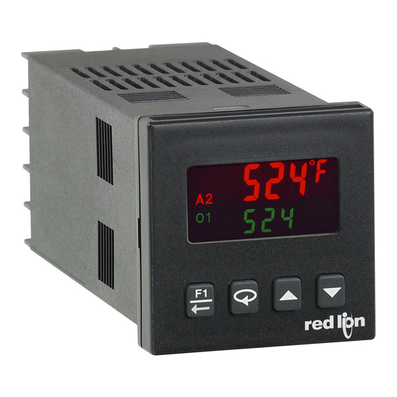
MODELS T16 & P16 - TEMPERATURE/PROCESS CONTROLLERS
GENERAL DESCRIPTION
The Model T16 Controller accepts signals from a variety of temperature
sensors (thermocouple or RTD), while the Model P16 Controller accepts either a
0 to 10 VDC or 0/4 to 20 mA DC input signal. Both controllers can provide an
accurate output control signal (time proportional or DC Analog Output) to
maintain a process at a setpoint value. Dual 4-digit displays allow viewing of the
process/temperature and setpoint simultaneously. Front panel indicators inform
the operator of the controller and output status. The comprehensive programming
allows these controllers to meet a wide variety of application requirements.
MAIN CONTROL
The controller operates in the PID Control Mode for both heating and
cooling, with on-demand auto-tune, that establishes the tuning constants. The
PID tuning constants may be fine-tuned through the front panel and then locked
out from further modification. The controller employs a unique overshoot
suppression feature, that allows the quickest response without excessive
overshoot. Switching to Manual Mode provides the operator direct control of the
output. The controller may also be programmed to operate in On/Off mode with
adjustable hysteresis.
ALARMS
Optional alarm(s) can be configured independently for absolute high or low
acting with balanced or unbalanced hysteresis. They can also be configured for
deviation and band alarm. In these modes, the alarm trigger values track the
setpoint value. Adjustable alarm hysteresis can be used for delaying output
response. The alarms can be programmed for Automatic or Latching operation.
A selectable standby feature suppresses the alarm during power-up until the
temperature stabilizes outside the alarm region.
ANALOG OUTPUT OPTION
The optional DC Analog Output (10 V or 20 mA) can be configured and
scaled for control or re-transmission purposes. The programmable output update
time reduces valve or actuator activity.
DIMENSIONS In inches (mm)
Courtesy of Steven Engineering, Inc.-230 Ryan Way, South San Francisco, CA 94080-6370-Main Office: (650) 588-9200-Outside Local Area: (800) 258-9200-www.stevenengineering.com
PID CONTROL WITH REDUCED OVERSHOOT
T16 ACCEPTS TC AND RTD
P16 ACCEPTS 0-10 V AND 0/4-20 mA SIGNALS
ON DEMAND AUTO-TUNING OF PID SETTINGS
DC ANALOG OUTPUT (OPTIONAL)
USER PROGRAMMABLE FUNCTION BUTTON
PC OR FRONT PANEL PROGRAMMING
PC CONFIGURABLE WITH TP16KIT
UL Recognized Component,
File #E156876
PC PROGRAMMING KIT
The optional TP16KIT contains a programming module with a 9 pin RS232
connector, cable and Crimson, a Windows
software allows downloading, uploading and storage of T16 and P16 program
files. All controllers have a communications port that allows configuration by
PC even without controller power connected. Controller calibration is also
possible using the software when the proper calibration equipment and
controller power is connected.
CONSTRUCTION
The controller is constructed of a lightweight, high impact, black plastic
textured case and bezel with a clear display window. The front panel meets
NEMA 4X/IP65 specifications when properly installed. In applications that do
not require protection to NEMA 4X, multiple controllers can be stacked
horizontally or vertically. Modern surface-mount technology, extensive testing,
plus high immunity to noise interference makes the controller extremely reliable
in industrial environments.
SAFETY SUMMARY
All safety related regulations, local codes and instructions that appear in the
manual or on equipment must be observed to ensure personal safety and to
prevent damage to either the instrument or equipment connected to it. If
equipment is used in a manner not specified by the manufacturer, the protection
provided by the equipment may be impaired.
Do not use the controller to directly command motors, valves, or other actuators
not equipped with safeguards. To do so can be potentially harmful to persons or
equipment in the event of a fault to the controller. An independent and redundant
temperature limit indicator with alarm outputs is strongly recommended.
CAUTION: Risk of Danger.
Read complete instructions prior to
installation and operation of the unit.
1-717-767-6511
®
based configuration software. The
CAUTION: Risk of electric shock.
PANEL CUT-OUT
541
F
Advertisement
Table of Contents

Subscribe to Our Youtube Channel
Related Manuals for red lion T16


Summary of Contents for red lion T16
- Page 1 GENERAL DESCRIPTION PC PROGRAMMING KIT The Model T16 Controller accepts signals from a variety of temperature sensors (thermocouple or RTD), while the Model P16 Controller accepts either a The optional TP16KIT contains a programming module with a 9 pin RS232 ®...
-
Page 2: General Specifications
- Measurement exceeds - sensor range ULUL 1. Self-recoverable loss of performance during EMI disturbance at 10 V/m: - Open sensor is detected (T16 only) OPEN Measurement input signal may deviate during EMI disturbance. - Shorted sensor is detected (RTD only) -
Page 3: Output Specifications
INPUT SPECIFICATIONS (Cont’d) 5. TEMPERATURE INDICATION ACCURACY: (T16 only) ± (0.3% of span, +1°C) at 23 °C ambient after 20 minute warm up. Includes 4. SIGNAL INPUT: (P16 only) NIST conformity, cold junction effect, A/D conversion errors and linearization conformity. -
Page 4: Block Diagram
Ferrite Suppression Cores for Signal and Control cables: 2. Use shielded (screened) cables for all Signal and Control inputs. The shield Fair-Rite # 0443167251 (Red Lion Controls # FCOR0000) (screen) pigtail connection should be made as short as possible. The TDK # ZCAT3035-1330A connection point for the shield depends somewhat upon the application. - Page 5 2.0 I NSTALLING THE ONTROLLER The T16 and P16 controllers meet NEMA 4X/IP65 requirements for indoor Instructions: use to provide a watertight seal in steel panels with a minimum thickness of 1. Prepare the panel cutout to the proper dimensions.
-
Page 6: Wiring Connections
3.0 W IRING THE ONTROLLER WIRING CONNECTIONS codes and regulations. It is recommended that power (AC or DC) supplied to the All wiring connections are made to the rear screw terminals. When wiring the controller be protected by a fuse or circuit breaker. Strip the wire, leaving controller, use the numbers on the label and those embossed on the back of the approximately 1/4"... -
Page 7: Display Loop
4.0 R EVIEWING THE RONT EYS AND ISPLAY FRONT PANEL KEYS The Arrow keys are used to scroll through parameter The F1 key is pressed to exit (or escape) directly to the start of the selections/values and in the Configuration Loop they are used to Display Loop. - Page 8 The values shown for the displays are the factory settings. SETPOINT VALUE (SP1) * INTEGRAL TIME Intt seconds -999 9999 9999 0. 0 Integral action shifts the center point position of the proportional band to eliminate error in the steady state. The higher the integral time, the slower the response.
- Page 9 Module 3-LC. Some parameters are model and programming dependent. controlled rate. R annunciator flashes while ramping. With the T16, the ramp rate is always in tenths of degrees per minute, regardless of the resolution chosen for the process display.
- Page 10 AUTO-TUNE START ACCESS CODE tUNE CodE NO YES -125 The Auto-Tune procedure of the controller sets the Proportional Band, If the Access Code is set from -1 to -125, in Lockout Module 3-LC, Access Integral Time, Derivative Time, Digital Filter, Control Output Dampening Code will appear here.
-
Page 11: Parameter Menu
7.1 MODULE 1 - I ) T16 O NPUT ARAMETERS PARAMETER MENU INPUT TYPE SETPOINT LOW LIMIT tYPE SPLO SELECTION TYPE SELECTION TYPE -999 9999 T TC N TC tc-t tc-N tc-j E TC C TC tc-E tc-C The controller has a programmable low setpoint limit value to restrict the... - Page 12 F1 KEY FUNCTION The controller performs the selected F1 Key Function, when is pressed while in the Display Loop. In any other loop or module location, pressing F1In will perform an escape to the Display Loop. NONE No Function: No function is performed. Auto/Manual Select: This function toggles (momentary action) the controller between Automatic and Manual Control.
-
Page 13: Setpoint Low Limit
INPUT VALUE SCALING POINT 2 F1 KEY FUNCTION F1In INP2 0. 0 0 20. 0 0 0. 0 0 10. 0 0 NONE 20. 0 0 SELECTION FUNCTION SELECTION FUNCTION For Key-in Method, enter the second coordinate Input Value by using the arrow keys. - Page 14 7.2 MODULE 2 - O UTPUT ARAMETERS PARAMETER MENU SENSOR FAIL POWER LEVEL CYCLE TIME OPFL CYCt percent O1 seconds 0. 0 250. 0 percent O1/O2 -100 2. 0 This parameter sets the power level for the control outputs in the event of a The Cycle Time is entered in seconds with one tenth of a second resolution.
- Page 15 ANALOG OUTPUT RANGE (OPTIONAL) ANALOG LOW SCALING (OPTIONAL) ANtP 0-10 0-20 4-20 4-20 0. 0 Select the type of output and range. The Analog output jumpers are factory The Analog Output assignment value that corresponds to 0 V, 0 mA or 4 mA set to current.
- Page 16 7.4 MODULE 4 - A ) (O LARM ARAMETERS PTIONAL PARAMETER MENU AVAILABLE ALARM ACTIONS No action, the remaining Alarm Alarm 1 and 2 value tracks the NONE None Deviation High d-HI parameters are not available. Setpoint value Alarm 1 and 2 value tracks the The alarm energizes when the Process d-LO Deviation Low...
- Page 17 ALARM ACTION ALARM 1 ALARM ANNUNCIATOR ALARM 2 ACt1 Lit2 NONE AbHI AbLO AuHI AuLO Normal Reverse AuHI d-HI d-LO b-IN b-ot HEAt Select the action for the alarms. See Alarm Action Figures for a visual With normal selection, the alarm annunciator indicates “on” alarm output 2. explanation.
- Page 18 7.5 MODULE 5 - C OOLING ECONDARY ARAMETERS PARAMETER MENU To enable Cooling in Heat/Cool applications, the Alarm 2 Action must first DEADBAND/OVERLAP be set for Cooling. (For P16 Controllers, the cooling output is sometimes db-2 referred to as secondary output.) When set to cooling, the output no longer -999 9999 operates as an alarm but operates as a cooling output.
- Page 19 They should be shielded from air movement and allowed sufficient time to equalize in temperature. (As an alternative, the T16 thermocouple may be placed in a calibration bath of known temperature.) If performing the millivolt calibration prior, verify that the correct input type is configured in Input Module 1-IN before performing the following procedure.
-
Page 20: Troubleshooting
Analog Output Calibration (T16 and P16) RESTORE FACTORY SETTINGS Set the controller Analog jumpers to the output type being calibrated. CodE Connect an external meter with an accuracy of 0.05% (or better) that is capable of measuring 10.00 V or 20.00 mA to terminals 6 (+V/I) and 7 (-V/I). The voltage or current calibration that is not being used must be skipped by pressing until End appears. -
Page 21: Control Mode Explanations
ONTROL XPLANATIONS ON/OFF CONTROL ON/OFF CONTROL - HEAT/COOL OUTPUT FIGURES The controller operates in On/Off Control when the Proportional Band is set to 0.0%. In this control mode, the process will constantly oscillate around the setpoint value. The On/Off Control Hysteresis (balanced around the setpoint) can be used to eliminate output chatter. -
Page 22: Pid Tuning Explanations
TIME PROPORTIONAL PID CONTROL MANUAL CONTROL MODE In Time Proportional applications, the output power is converted into output In Manual Control Mode, the controller operates as an open loop system On time using the Cycle Time. For example, with a four second cycle time and (does not use the setpoint and process feedback). -
Page 23: Manual Tuning
This procedure is an alternative to the controller’s Auto- Tune function. It will not provide acceptable results if system problems exist. 1. Set the Proportional Band (ProP) to 10.0% for temperature models (T16) and 7. If the process is stable, decrease Proportional Band setting by two times and 100.0% for process models (P16). -
Page 24: Parameter Value Chart
Auto OUTPUT POWER ACCESS dISP tUNE AUTO-TUNE START PID VALUE ACCESS HIdE ALARM VALUE ACCESS HIdE INPUT MODULE ( ) T16 ONLY ACCESS CODE CodE 1-IN SPSL SETPOINT SELECT ACCESS DISPLAY PARAMETER FACTORY SETTING USER SETTING SPrP SETPOINT RAMP ACCESS... -
Page 25: Quick Overview
T16 & P16 P ROGRAMMING UICK VERVIEW 1-717-767-6511 Courtesy of Steven Engineering, Inc.-230 Ryan Way, South San Francisco, CA 94080-6370-Main Office: (650) 588-9200-Outside Local Area: (800) 258-9200-www.stevenengineering.com...
Need help?
Do you have a question about the T16 and is the answer not in the manual?
Questions and answers