Table of Contents
Advertisement
Quick Links
Advertisement
Table of Contents

Subscribe to Our Youtube Channel
Related Manuals for red lion TSC


Summary of Contents for red lion TSC
- Page 1 THE TEMPERATURE SETPOINT CONTROLLER MODEL TSC INSTRUCTION MANUAL...
- Page 2 The TSC unit, which you have purchased, has the same high quality workmanship and advanced technological capabilities that have made Red Lion Controls the leader in today’s industrial market.
-
Page 3: Table Of Contents
TABLE OF CONTENTS GENERAL DESCRIPTION INSTALLATION & CONNECTIONS 7-13 A) Standard Unit Installation & Removal B) NEMA 4X/IP65 Unit Installation C) Unit Removal Procedure D) Removing Bezel Assembly E) Installing Bezel Assembly F) Output Modules 1. Output Variations without RS-485 Option 2. - Page 4 TABLE OF CONTENTS OPERATION OVERVIEW (Cont’d) 15-24 F) Controlling A Profile (Cont’d) 18-21 1. Profile Start Operation (Cont’d) d. Start Operation On Power-Up e. Start Operation Via The RS-485 Serial Option 2. Profile Stop Operation a. Stop Operation From The Profile Control Status Display b.
- Page 5 TABLE OF CONTENTS UNPROTECTED PARAMETER MODE A) Reference Table PROTECTED PARAMETER MODE 26-27 A) Reference Table B) Front Panel Program Disable VII) HIDDEN FUNCTION MODE A) Reference Table VIII) CONFIGURATION PARAMETER MODULES 29-57 A) Input Module 29-31 1. Input Type 2.
- Page 6 TABLE OF CONTENTS VIII) CONFIGURATION PARAMETER MODULES (Cont’d) 29-57 E) Cooling Output Module (Optional) 39-40 1. Cooling Cycle Time 2. Cooling Relative Gain 3. Heat-Cool Overlap/Deadband F) Serial Communications Module (Optional) 1. Baud Rate 2. Parity Bit 3. Address Number 4.
- Page 7 TABLE OF CONTENTS PID CONTROL 66-68 A) Proportional Band B) Integral Time 66-67 C) Derivative Time D) Output Power Offset (Manual Reset) E) PID Adjustments 67-68 XII) ON/OFF CONTROL 69-70 XIII) AUTO-TUNE 71-72 A) To Initiate Auto-Tune B) To Cancel Auto-Tune XIV) APPENDIX A - APPLICATION EXAMPLES APPENDIX B - SPECIFICATIONS &...
-
Page 8: General Description
(Absolute HI or LO, Deviation HI or LO, or The TSC has been designed to simplify the set-up and operation of a controlled Band IN or OUT) with adjustable hysteresis. Also, a standby feature suppresses setpoint profile program. -
Page 9: Ii) Installation & Connections
Continuous exposure to direct sunlight may accelerate the aging process of the Do not use the TSC to directly command motors, valves, or other actuators not bezel. The bezel should be cleaned only with a soft cloth and neutral soap equipped with safeguards. - Page 10 PANEL INSTALLATION & REMOVAL Note: The installation location of the controller is important. Be sure to keep it Note: Prior to applying power to the controller, the internal AC power selector away from heat sources (ovens, furnaces, etc.), away from direct contact with switch must be set.
-
Page 11: C) Unit Removal Procedure
Unit Removal Procedure To remove a NEMA 4X/IP65 or standard unit from the panel, first unscrew and remove the panel latch screws. Insert flat blade screwdrivers between the latch and the case on the top and bottom of the unit so that the latches disengage from the grooves in the case. -
Page 12: F) Output Modules
Output Modules Installing Output Modules To install an output module into the controller, remove the bezel assembly The main control, optional alarm, and optional cooling output sockets must be from the case (see Removing Bezel Assembly). Locate the correct output fitted with the appropriate output module. -
Page 13: G) Select Input Sensor Type
Select Input Sensor Type The input sensor type (thermocouple or RTD) must be selected by an internal hardware jumper to match the input sensor type programmed. The jumper is located inside the case on a small accessory circuit board near the rear of the unit on the main circuit board (See hardware selection figure and/or label on outside of case). -
Page 14: H) Select Ac Power (115/230)
Select AC Power (115/230VAC) 5. In extremely high EMI environments, the use of external EMI suppression devices, such as ferrite suppression cores, is effective. Install them on Signal The AC power to the unit must be selected for either 115VAC or 230VAC. and Control cables as close to the unit as possible. -
Page 15: Signal Wiring
Signal Wiring Thermocouple Connection When connecting the thermocouple or RTD leads, be certain that the connections are clean and tight. If the thermocouple probe cannot be connected directly to the controller, thermocouple wire or thermocouple extension-grade wire must be used to extend the connection points (copper wire will not work). Always refer to the thermocouple manufacturer’s recommendations for mounting, temperature range, shielding, etc. -
Page 16: Iii) Front Panel Description
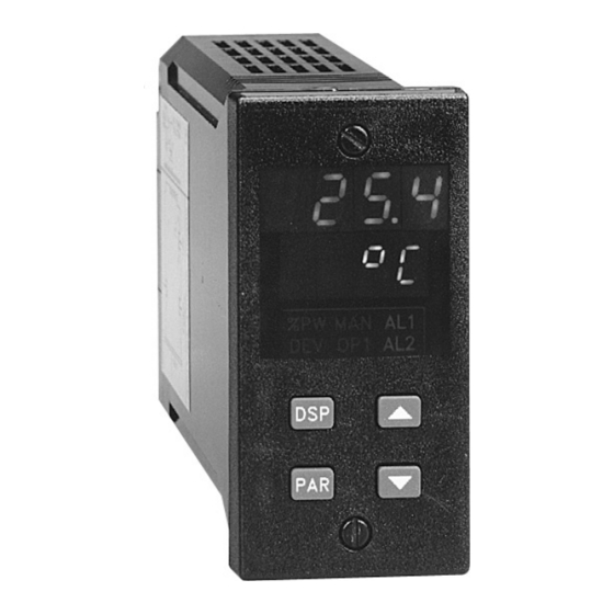
FRONT PANEL DESCRIPTION The front panel bezel material is flame and scratch resistant tinted plastic. Available is an optional NEMA 4X/IP65 version which has a bezel that meets NEMA 4X/IP65 requirements, when properly installed. There are two 4-digit LED displays, a red upper Main Display and a lower green Secondary Display. -
Page 17: Iv) Operation Overview
OPERATION OVERVIEW B) Use a manual tuning technique (see manual tuning). C) Use a third party tuning software package package (generally expensive and Controller Power-up not always precise). D) Use values based on control loop experience or values from a similar process. Upon applying power, the controller delays control action and temperature If the controller is a replacement, the PID settings from the unit being replaced indication for five seconds to perform several self-diagnostic tests and displays... -
Page 18: E) Profile Operating Modes
Profile Operating Modes Pause Mode The pause mode signifies that a profile is active but the time base is stopped. Run Mode The pause mode is caused only by a manual action. Pausing a profile during a The controller is in the Run Mode when a profile is executing. While in the ramp phase stops the ramp and the controller maintains the setpoint value at the Run Mode, the profile can be stopped (Off Mode), paused (Pause Mode) or instant of the pause action. -
Page 19: Delay Mode
Delay Mode The Delay Mode signifies that a profile is active but the time base, or profile advancement is stopped. This is caused by automatic action of the controller when the input temperature deviates more than a specified amount from the profile setpoint. -
Page 20: F) Controlling A Profile
Shown below is a typical command string. 3. Press and hold the “PAR” button for three seconds to enter the hidden mode. Start profile 2 of TSC unit 6. 4. Scroll to “Prun” (if necessary) by pressing the “PAR” button. N6CU2* 5. -
Page 21: Profile Stop Operation
Transmit the unit address, command letter, with the value identifier and number via the serial port (see serial communication section for details). Shown below is a typical command string. Stop the currently running profile of TSC unit 6. N6CU5* -19-... -
Page 22: Advance Operation From The Hidden Mode
(see serial communication section for details). Shown below is a typical command string. Shown below is a typical command string. Advance the currently running profile of TSC unit 6 to the next phase. Pause the currently running profile of TSC unit 6. N6CU8*... -
Page 23: Continue Operation From The Hidden Mode
A timed event output can be reset via the serial communications option. Transmit the unit address, command letter, with the value identifier via the serial port (see serial communication section, for details). Shown below is a typical command string. Reset timed event output 2 of TSC unit 6. N6RH* -21-... -
Page 24: G) Configuration Of Parameters
Configuration Of Parameters Operation and configuration of the controller is divided into five distinct As supplied from the factory, the controller parameters have been operational/programming modes to simplify the operation of the controller: programmed to the values listed in the Quick Reference Tables. The user must Normal Display Mode, Unprotected Parameter Mode, Protected Parameter modify the values, if necessary, to suit the application. -
Page 25: H) Parameter Entry
Parameter Entry Modifying A Secondary Display Parameter From The Front Panel The controller must be in the normal display mode to modify any of the The PAR button is used to select the desired parameter. To modify the secondary display parameters. Temperature units symbol indicates the parameter setting use the UP and DOWN buttons, and then press PAR to enter the temperature scale (°F or °C) and cannot be modified from this mode. -
Page 26: Output Power Display
% Output Power Display Profile Phase Time Remaining Display The % output power can only be changed when the unit is in the manual mode. The annunciator PGM lights when either the phase time remaining or the The annunciator %PW lights when viewed, then use the up and down arrow profile control status is viewed. -
Page 27: Unprotected Parameter Mode
Unprotected Parameter Mode Reference Table UNPROTECTED PARAMETER MODE Range and Units The Unprotected Parameter Mode is accessed by pressing Display Parameter Description/Comments (Factory Setting Value) the PAR button from the normal display mode with program Temperature Must be within range of limits Appears only if setpoint value is locked (LOC) or read disable inactive. -
Page 28: Vi) Protected Parameter Mode
Protected Parameter Mode Reference Table PROTECTED PARAMETER MODE The Protected Parameter Mode is accessed from the normal Range and Units display mode by pressing the PAR button with program disable Display Parameter Description/Comments (Factory Setting Value) active. In this mode, the operator has access to the list of the ProP Proportional Band 0.0 to 999.9% of selected... -
Page 29: B) Front Panel Program Disable
Front Panel Program Disable There are several ways to limit operator access to the programming of parameters from the front panel buttons. The settings of the parameters in the parameter lockout module, the code number entered, and the state and/or function of the user input (terminal #7) affect front panel access. -
Page 30: Vii) Hidden Function Mode
Hidden Function Mode Reference Table HIDDEN FUNCTION MODE The Hidden Function Mode is only accessible from the Range and Units Display Parameter Description/Comments normal display mode by pressing and holding the PAR (Factory Setting Value) button for three seconds. In this mode, five controller Load Control Point This step does not appear if locked (LOC). -
Page 31: Viii) Configuration Parameter Modules
CONFIGURATION PARAMETER MODULES Temperature Scale (SCAL) Select either degrees Fahrenheit (°F) or degrees Celsius (°C). If changed, be Accessible from the unprotected parameter mode, the configuration sure to check All parameters. parameter modules allow the operator access to the controller’s fundamental Temperature Resolution (dCPt) set-up parameters. -
Page 32: Input Sensor Correction Constants
Input Module (1- IN) (Cont’d) Auto Setpoint Ramp Rate (SPrP) The setpoint can be programmed to ramp independent of the controller’s Input Sensor Correction Constants (SPAN & SHFt) display resolution. The setpoint ramp rate can reduce thermal shock to the If the controller temperature disagrees with a reference temperature process, reduce temperature overshoot on start-up or setpoint changes, or ramp instrument or if the temperature sensor has a known calibration, the controller... -
Page 33: User Input
User Input (InPt) The User Input requires the input to be in its active state for 100msec minimum CP - Control Point Select. A high to low transition loads Control Point 2 into the to perform the function. The unit will execute all functions in 100msec, except memory of the controller. -
Page 34: B) Output Module
Output Module (2-OP) Output Power Limits (OPLO & OPHI) Enter the safe output power limits for the process. These parameters may also The controller has parameters which affect how the main control output (OP1) be used to limit the minimum and maximum controller power due to process responds to temperature changes and sensor failures. -
Page 35: Auto-Tune Damping Code
Auto-Tune Damping Code (tcod) With high and low digital scaling points, the range of the Linear DC output can Prior to invoking Auto-Tune, the damping code should be set to achieve the be set independent of the controller’s range. desired damping level under PID control. When set to 0, this yields the fastest ANLO (4mA or 0VDC) - -999 to 9999 process response with some overshoot. -
Page 36: C) Lockouts Module
Lockouts Module (3-LC) Protected Mode Lockouts (Code, PID, & AL) The protected mode is active when program disable is active. The PID and The controller can be programmed to limit operator access to various Alarm parameters can be set for one of the following: parameters, control modes, and display contents. -
Page 37: D) Alarm Module
Red Lion Controls model IMT (thermocouple) or model IMR (RTD) units may be used for this purpose. The indicators should have independent input sensors and AC power feeds from the other equipment. - Page 38 -36-...
- Page 39 -37-...
-
Page 40: Alarm Reset
Alarm Reset (rSt1, rSt2) Alarm Standby Delay (Stb1, Stb2) Each alarm reset action may be independently configured. The alarm(s) may be independently configured to exhibit a power-on, standby delay which suppresses the alarm output from turning “ON” until the LAtC - Latching temperature first stabilizes outside the alarm region. -
Page 41: Alarm Hysteresis
Alarm Hysteresis (AHYS) Cooling Relative Gain (GAN2) The alarm(s) values have a programmable hysteresis band to prevent alarm This parameter defines the gain of the cooling band relative to the heating output chatter near the alarm trigger temperature. The hysteresis value should be band. -
Page 42: Heat-Cool Overlap/Deadband
Heat-Cool Overlap/Deadband (db-2) This parameter defines the area in which both heating and cooling are active (negative value) or the deadband area between the bands (positive value). The parameter units are degrees or tenth’s of degrees (depending on system resolution). If a heat/cool overlap is specified, the displayed percent output power is the sum of the heat power (OP1) and the cool power (OP2). -
Page 43: F) Serial Communications Module (Optional)
Selecting YES for the print options will allow the operator to scroll through the When communicating with a TSC unit via the serial port, the data formats of available options using the PAR button. The up and down arrow keys toggle both units must be identical. -
Page 44: G) Control Points Module
Control Points Module (7-CP) Profiles Module (8-Pr) There are four Control Points, each having a setpoint value and an associated Prior to programming a profile, it is recommended to configure the basic PID gain set value. A control point can be implemented at any time to controller operation. -
Page 45: Profile Cycle Count Parameter
Profiles Module (8-Pr) (Cont’d) Profile Linking (PnLn) PROFILE Each profile can have up to eight ramp and eight hold phases programmed. If more than eight phases are required, profiles may be linked together. Linking allows the next profile to automatically start when the current profile has completed its cycle count. -
Page 46: Profile Power Cycle Status Parameter
Profile Power Cycle Status (PnSt) Ramp Phase (Pnrn) Upon controller power-on, several profile operating modes exist. Each profile The ramp phase is defined as automatic changing (ramping) of the setpoint has an independent power cycle status. value over a discrete time period at a predefined rate. The ramp rate is expressed in tenths of degree per minute. -
Page 47: Setpoint Value
Setpoint Value (PnLn) Each phase of the profile corresponds to an Event Output number. One of the The controller ramps to the Target Setpoint Value and then maintains the output state assignments is programmed to each profile phase. The table lists the Target Setpoint Value over the hold phase time. -
Page 48: Timed Event Output
Timed Event Output(s) (Pn 1 to Pn 16) (Cont’d) TIMED EVENT OUTPUT(S) It is possible to have the Event Outputs operate during Timed Event Output Phase profile phases by creating ‘phantom’ phases, whose sole Number State function is to allow a new state of Event Outputs. Pnr1 Pn 1 1N2F... -
Page 49: Profile Example
Profile Example PROFILE EXAMPLE The following example shows the set-up of a profile that executes one time and uses the timed event outputs. General Requirements: 1. Program data into profile 1. 2. Delay profile if temperature is not within 8 degrees, only during hold phases. -
Page 50: I) Factory Service Operations
The Programming Data For The Example: Profile Module 8 (8-Pr) (Cont’d) Mnemonic Value Description Input Module 1 (1-IN) P1 1 1F2F Keep both outputs off P1 2 1F2F Keep both outputs off Mnemonic Value Description P1 3 1F2F Keep both outputs off InPt P1rH User input is programmed for run/pause... -
Page 51: Ix) Quick Reference Tables For Configuration Parameter Modules
Quick Reference Table: Configuration Input Module 1 (1-IN) Range and Units Description/ Display Parameter (Factory Setting Value) Comments tYPE Input type tc-t - Type T TC If changed, check PID settings tc-E -Type E TC and input select jumper tc-J - Type J TC position. - Page 52 Quick Reference Table: Configuration Output Module 2 (2-OP) Range and Units Description/ Display Parameter (Factory Setting Value) Comments CYCt Cycle time 0 to 120 seconds 0 turns OP1 off. OPAC Control action drct - cooling For both PID & ON/OFF control. rEv - heating (rev) OPLO...
- Page 53 Quick Reference Table: Configuration Lockout Module 3 (3-LC) Display Parameter Range and Units Description/ (Factory Setting Value) Comments Setpoint access - lockout Allows access to temperature - read only setpoint. - enter (Ent) Output power - lockout Allows direct access to out- access - read only put power.
- Page 54 Quick Reference Table: Configuration Alarms Module 4 (4-AL) Unit returns to configuration access point if alarm(s) are not installed. Display Parameter Range and Units Description/ (Factory Setting Value) Comments Act1 Alarm 1 A-HI absolute high If changed, check alarm values. If P-Ev operation A-LO absolute low is selected, remaining parameters for...
- Page 55 Quick Reference Table: Configuration Cooling Module 5 (5-O2) Unit returns to configuration access point if cooling option not installed. Display Parameter Range and Units Description/ (Factory Setting Value) Comments CYC2 Cooling output 0 to 120 sec 0 turns OP2 off. cycle time GAN2 Relative...
- Page 56 Reference Table: Configuration Serial Communications Module 6 (6-SC) Unit returns to configuration access point if RS-485 serial option is not installed. Range and Units Description/ Display Parameter (Factory Setting Value) Comments bAUd Baud rate 300 to 9600 Baud rate of unit must (1200) match other equipment.
- Page 57 Quick Reference Table: Configuration Control Point Module 7 (7-CP) Display Parameter Range and Units Description/ (Factory Setting Value) Comments CSEt Control Point NO - Return to CONF set-up CP-1 Control Point 1 CP-2 Control Point 2 CP-3 Control Point 3 CP-4 Control Point 4 (NO)
- Page 58 Quick Reference Table: Configuration Profile Module 8 (8-Pr) Display Parameter Range and Units Description/ (Factory Setting Value) Comments PSEt Setpoint Profile NO - Return to CNFP Pr-1 Profile 1 Pr-2 Profile 2 Pr-3 Profile 3 Pr-4 Profile 4 PE-1 Time event output for profile 1 PE-2 Time event output for profile 2 PE-3...
- Page 59 Quick Reference Table: Configuration Profile Module 8 (8-Pr) (Cont’d) Display Parameter Range and Units Description/ (Factory Setting Value) Comments The parameters for the four timed event outputs are the same. (Pn = Timed Event Output for proflile 1, 2, 3, or 4.) Pn 1 Event output 1F2F...
-
Page 60: X) Rs-485 Serial Communications Interface (Optional)
When sending commands to a TSC unit, a command string must be TSC unit are 1 start bit, 7 data bits, No parity or 1 parity bit (odd or even) and 1 constructed. The command string may consist of command codes, value stop bit. - Page 61 The Data value need not contain the decimal point since it is fixed within the unit, when programmed at the front panel. The TSC will Ex. 4 Start profile 1 of the unit with an address of 13.
-
Page 62: C) Receiving Data
Receiving Data When writing application programs in Basic, the transmission of spaces or Data is transmitted from the TSC when a “T” Transmit Value or a “P” carriage return and line feed should be inhibited by using the semicolon delimiter Transmit Print Options command is sent to the unit via the serial port. - Page 63 If more than one string is transmitted, there is a 100msec minimum to 200msec A print out from a TSC unit with an address of 1 and all print options selected is maximum built-in time delay after each transmission string and after each block shown below: of transmission.
-
Page 64: D) Terminal Emulation Program
PC Basic. The program may need to be modified if using a different basic Utilizing the Serial communications capability of the TSC requires the use of interpreter. Set up the TSC for a baud rate of 9600. When the program is running, ®... -
Page 65: E) Serial Connections
RS-485 transceiver lines. The signal ground is connected at the RS-485 common of only one TSC unit to the RS-485 equipment. If necessary, the shield can be used as the signal ground. -
Page 66: Connecting To An Rlc Printer
The GCM422 module must have the internal jumper placed in the 485 position. The 25 pin connector on the GCM422 module must have pins 2 & 3 and 14 & 16 jumpered. The TSC must be programmed for the same baud rate as the printer. When more than one controller is on the line, each TX EN terminal is connected to the transmit disable pin of the GCM422 module. -
Page 67: Connecting To A Host Terminal
Connecting To A Host Terminal An application program is written to send and receive data from the units using Six TSC units are used to control a process in a plant. The TSC units are the proper commands. located at the proper location to optimize the process. A communication line is run to an industrial computer located in the production office. - Page 68 PID CONTROL Integral Time Integral time is defined as the time, in seconds, in which the output due to Proportional Band integral action alone equals the output due to proportional action with a constant process error. As long as a constant error exists, integral action will “repeat” the Proportional band is defined as the “band”...
- Page 69 Integral Time (Cont’d) changes the output before it actually “arrives”. Increasing the derivative time helps to stabilize the response, but too much derivative time coupled with noisy If integral action is disabled (Automatic Reset), manual reset is available by signal processes, may cause the output to fluctuate too greatly yielding poor modifying the output power offset (“OPOF”...
- Page 70 PROCESS RESPONSE EXTREMES -68-...
- Page 71 ON/OFF CONTROL COOLING OUTPUT (OP2) MAIN CONTROL OUTPUT (OP1) The controller can operate in the ON/OFF control mode by setting the proportional band = 0.0 The ON/OFF control hysteresis band (CHYS) parameter can be used to eliminate output chatter around setpoint. The cooling output can also be used in the ON/OFF control by setting the relative gain = 0.0 The phase of the control action can be reversed...
- Page 72 ON/OFF CONTROL ON/OFF and PID control can be used for the heat and cool output in several combinations. The following lists the valid control modes: OP1 & OP2 VALID CONTROL MODES MANUAL MODE OP1 MODE OP2 MODE OP1 STATE OP2 STATE OUTPUT POWER RANGE 0% to +100.0% OP1-TP...
- Page 73 AUTO-TUNE Auto-Tune is a user initiated function in which the controller automatically determines the optimum PID AUTO-TUNE OPERATION FIGURE settings based upon the process characteristics. The desired temperature setpoint should be entered first. Auto-Tune may then be initiated at start-up, from setpoint, or at any other process temperature point.
- Page 74 AUTO-TUNE (Cont’d) To Initiate Auto-Tune: Make sure that Auto-Tuning is enabled in parameter lockouts module. A damping code setting of 0 gives the fastest response with some overshoot, Place the controller into the normal display mode. and a code of 4 gives the slowest response with minimum overshoot. Press PAR for 3 seconds from normal display mode.
- Page 75 Different tempering profiles are required for different types of glass products. A TSC is employed to control the temperature profile of the annealing oven. Four different temperature profiles are stored in the controller. The 4-20mA analog output option is utilized to cool the annealing oven during the cool down ramp phases.
- Page 76 APPENDIX “B” - SPECIFICATIONS AND DIMENSIONS 1. DISPLAY: Dual 4-digit 3. ANNUNCIATORS: Upper Temperature Display: 0.4" (10.2 mm) High Red LED 6 LED Backlight Status Indicators: Lower Auxiliary Display: 0.3" (7.6 mm) High Green LED Lower auxiliary display shows power output in (%). Lower auxiliary display shows profile status or profile time remaining.
- Page 77 5. SETPOINT PROFILE: 9. RTD: 2, 3 or 4 wire, 100W platinum, Profiles: 4 alpha = 0.00385 (DIN 43760), Segments Per Profile: 8 ramp/hold segments (linkable to 32 segments). alpha = 0.003916 Ramp Rate: 0.1 to 999.9 degrees/minute or step ramp. Excitation: 0.175 mA Hold Time: Off or from 0.1 to 999.9 minutes, can be extended to 500 Resolution: 1 or 0.1 degree...
- Page 78 APPENDIX “B” - SPECIFICATIONS & DIMENSIONS (Cont’d) 14. LINEAR DC DRIVE (Optional): With digital scale and offset, 11. OUTPUT MODULES [Optional] (For All Output Channels): Relay: programmable deadband and update time.. Type: Form-C (Form-A with RS-485 option) 4-20mA: Rating: 5 Amps @ 120/240 VAC or 28 VDC (resistive load), Resolution: 1 part in 3500 typical 1/8 HP @ 120 VAC (inductive load).
- Page 79 17. USER INPUT: Internally pulled to +5VDC; V Max = 5.25VDC, Notes: = .85V = 2.0V , Response time 100msec maximum. 1. Self-recoverable loss of performance during EMI disturbance at 10 V/m: Analog output signal may deviate during EMI disturbance. Functions: Program Lock Print Request...
- Page 80 The majority of problems can be traced to improper connections or incorrect set-up APPENDIX “C” - TROUBLESHOOTING parameters. Be sure all connections are clean and tight, that the correct output module is fitted, and that the set-up parameters are correct. For further technical assistance, contact technical support at the numbers listed on the back cover of the instruction manual.
- Page 81 APPENDIX “C” - TROUBLESHOOTING (Cont’d) Problems Possible Cause Remedies “OPEN” IN DISPLAY 1. Probe disconnected. 1. Connect probe. 2. Input selector jumper in wrong position. 2. Verify correct jumper position. 3. Broken or burned out probe. 3. Replace probe. 4. Corroded or broken terminations. 4.
- Page 82 APPENDIX “C” - TROUBLESHOOTING (Cont’d) Problems Possible Cause Remedies TEMPERATURE NOT 1. Incorrect PID values. 1. See PID CONTROL. STABLE OR SLUGGISH 2. Heater undersized. 2. Increase heating power. 3. Improper probe location. 3. Evaluate probe location. OUTPUTS NOT WORKING 1.
- Page 83 Output Leakage Current The AL1 and AL2/OP2 outputs of the TSC have an RC Network (Snubber) on the Normally Open contacts. High energy noise spikes are generated whenever current through an inductive load (such as motors, solenoids or relay coils) is interrupted.
- Page 84 APPENDIX “D” - MANUAL TUNING Open Loop Step Response Method Damped Slow Parameter Fast Response The Open Loop Step Response Method is a tuning procedure that does not Response Response induce process oscillations. This method involves making a step change to the Proportional Band (%) 20000a 40000a...
- Page 85 Closed Loop Cycling Method An alternative to auto-tuning is manual tuning. This tuning method induces oscillations into the process in the same way as the controller’s auto-tune function. If oscillations are not acceptable, the open-loop tuning method can be used. The following is a manual tuning procedure for determination of the PID control constants.
- Page 86 APPENDIX “E” - CALIBRATION Calibration Check RTD Ohms Reading The instrument has been fully calibrated at the factory for ALL thermocouple 1) Place the input sensor jumper in the RTD position. and RTD types. If the unit appears to be indicating or controlling incorrectly, 2) Connect RTD simulator to terminals #8, #9, &...
- Page 87 Configure Step 9 - Factory Service Operations (9-FS) Calibration When calibration is required (generally every two years), Display Parameter Description/Comments this procedure should only be performed by qualified Code Enter factory technicians using appropriate equipment. Equipment source service Calibrate instrument function code accuracies of 0.01% or better are required.
- Page 88 Thermocouple Cold Junction Calibration (CJC) Analog Output Calibration (ANCL) 4 to 20 mA This procedure must be performed AFTER an accurate mV calibration. Place Press PAR until ANCL appears in the display. Connect precision ammeter the internal input sensor selection jumper to “TC” position. Place precision (0.1% accuracy) to rear terminals (+) #11 and (-) #12.
- Page 89 APPENDIX “F” - USER PARAMETER VALUE CHART Unit Number Configure Lockouts Configure Serial Communications Mnemonic Parameter User Setting Mnemonic Parameter User Setting Mnemonic Parameter User Setting Temperature Setpoint Access Setpoint bAUd Baud Rate OPOF Output Power Offset Access Output Power PArb Parity Bit Output Power...
- Page 90 APPENDIX “F” - USER PARAMETER VALUE CHART (Cont’d) Configure Control Points Mnemonic Parameter User Setting Mnemonic Parameter User Setting Pr-1 Pr-2 Pr-3 Pr-4 CP-1 CP-2 CP-3 CP-4 PnH6 Profile Hold Time 6 Setpoint Value Pnr7 Profile Ramp Rate 7 YES/NO Load With Pnl7 Profile Setpoint Level 7 Setpoint Value...
- Page 91 APPENDIX “G” - ORDERING INFORMATION NEMA 4 to 20 mA 0 to 10 VDC MODEL ALARM COOLING RS485 DESCRIPTION 4X/IP65 ANALOG ANALOG PART NUMBER OUTPUTS OUTPUT BEZEL OUTPUT OUTPUT Temperature Setpoint Controller TSC01001 TSC11001 TSC11002 TSC11004 TSC11005 TSC12004 TSC12005 Relay Module OMD00000 Triac Module OMD00001...
- Page 92 The Company’s option. The Company disclaims all liability for any affirmation, promise or representation with respect to the products. The customer agrees to hold Red Lion Controls harmless from, defend, and indemnify RLC against damages, claims, and expenses arising out of subsequent sales of RLC products or...
- Page 93 TSC/IM - A 5/01 DRAWING NO. LP0275 Red Lion Controls Red Lion Controls France Red Lion UK Ltd 20 Willow Springs Circle 56 Boulevard du Courcerin, Batiment 21, Tapton Park York PA 17402 ZI Pariest F-77183 Croissy Beaubourg Chesterfield S41 OTZ...
Need help?
Do you have a question about the TSC and is the answer not in the manual?
Questions and answers