
Subscribe to Our Youtube Channel
Related Manuals for Husqvarna 430XH


Summary of Contents for Husqvarna 430XH
- Page 1 Operator's manual ® HUSQVARNA AUTOMOWER 430XH/450XH EN, English Read the operator's manual carefully and make sure that you understand the instructions before you use the product.
-
Page 2: Table Of Contents
Contents 1 Introduction 6 Troubleshooting 1.1 Support............3 6.1 Introduction - troubleshooting....40 1.2 Product description........3 6.2 Fault messages........40 1.3 Product overview........4 6.3 Information messages......45 1.4 Symbols on the product......5 6.4 LED indicator lamp on the charging 1.5 Symbols on the display......5 station.............47 1.6 Symbols on the battery.......6 6.5 LED indicator lamp on the product... -
Page 3: Introduction
PIN code: The serial number is on the product rating plate and on the product carton. • Use the serial number to register your product on www.husqvarna.com. 1.1 Support The operator selects the operation settings with the keys on the keypad. The display shows the... -
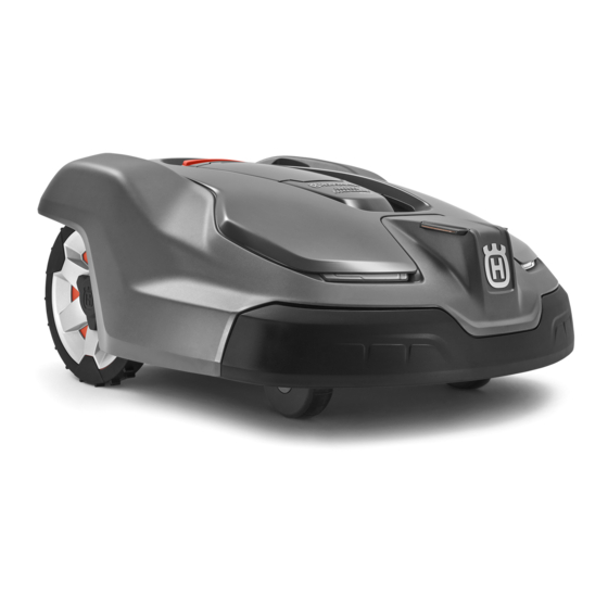
Page 4: Product Overview
1.3 Product overview Automower® 430XH Automower® 450XH The numbers in the figure represent: 15. Handle 16. Blade disc Body 17. Skid plate Hatch to display and keypad 18. Contact plates Stop button 19. LED for operation check of the charging... -
Page 5: Symbols On The Product
29. Couplers for the loop wire This product conforms to the 30. Loop wire for boundary loop and guide wire applicable EC Directives. 31. Stakes Noise emission to surroundings. The 32. Connectors for the loop wire product’s emissions are set out in Technical data on page 54 and on the 1.4 Symbols on the product rating plate. -
Page 6: Symbols On The Battery
The messages function shows error The GPS-supported navigation is messages and possible cause for the active. Flashes as it collects GPS problems. information. The weather timer function The GPS-supported navigation is not automatically adapts the cutting active. intervals to the grass growth. The bars show the signal strength of The installation function for manual ®... -
Page 7: Menu Structure Overview 1
1.7 Menu structure overview 1 Timer Overview Timer settings Overview (per day) Period 1 Period 2 Copy to Reset Current All week days Cutting height Cutting height Security Advanced Security level New loop Change Duration Medium High Custom signal PIN code Duration Duration of alarm... -
Page 8: Menu Structure Overview 2
1.8 Menu structure overview 2 Weather timer Cutting time Medium High Installation Find charging station Advanced Lawn coverage Overview of search method GPS Auto Overview of Guide Boundary Charger lawn coverage Charging Area 1-5 station range Delay time Disable More How? Disable More... -
Page 9: Menu Structure Overview 3
1.9 Menu structure overview 3 Settings Profiles ECO mode Spiral cutting Slope control General Profile A, B or C Time & Language Country & Reset all About date Timezone user setting Select Rename Save Intensity Set time Set date Time format Date format Low- Medium High... -
Page 10: Display
1.10 Display The display on the product shows information and settings of the product. To access the display, push the STOP button. 1.11 Keypad The keypad on the product let the operator navigate in the menu of the product. To access the keypad, push the STOP button. -
Page 11: Safety
2 Safety 2.1 Safety definitions 2.2 General safety instructions Warnings, cautions and notes are used to point The following system is used in the Operator’s out specially important parts of the manual. Manual to make it easier to use: italics is a text that is shown •... - Page 12 2.2.1 IMPORTANT. READ CAREFULLY BEFORE USE. KEEP FOR FUTURE REFERENCE The operator is responsible for accidents or hazards occurring to other people or property. This appliance is not intended for use by persons (including chil- dren) with reduced physical, sensory or mental capabilities (that could affect a safe handling of the product), or lack of experience and knowledge, unless they have been given supervision or in- struction concerning use of the appliance by a person responsible...
-
Page 13: Safety Instructions For Operation
WARNING: The product Warning! Automatic lawnmower! Keep away from the machine! Supervise children! can be dangerous if used incorrectly. Warning! WARNING: Do not use Automatic lawnmower! Keep away from the machine! the product when Supervise children! persons, especially children, or animals, are in the work area. - Page 14 Refer to settings on page 24 . Carry the product by the handle under the • Husqvarna does not guarantee full product with the blade disc away from the compatibility between the product and other body. types of wireless systems such as remote...
- Page 15 2.3.5 In the event of a thunderstorm CAUTION: Do not lift the product when it is parked in the charging station. It can damage the charging station and/or the product. Press STOP and pull the product out of the charging station before lifting it.
-
Page 16: Installation
• Put the charging station on a level surface. Note: Refer to www.husqvarna.com for more information about installation. max. 5 cm / 2" 3.2 Before the installation of the wires max. 5 cm / 2"... - Page 17 3.3.2 To examine where to put the power recommended to make an eyelet where the guide wire will be connected. Make the eyelet with supply approximately 20 cm / 8 in. of the boundary wire. • Put the power supply in an area with a roof and protection from the sun and rain.
- Page 18 0-15% 0-15 cm / 0-6" 100 cm / 40" 40 cm / 16" > 5 cm/>2" • For slopes steeper than 45% inside the work area, isolate the slope with boundary wire. • Put the boundary wire 35 cm / 14 in. (C) •...
- Page 19 0 cm / 0" CAUTION: Do not put a section of • Put the boundary wire around the secondary boundary wire across the other. area (B) to make an island. Refer to The sections of boundary wire make an island on page 18 . must be parallel.
-
Page 20: Installation Of The Product
30 cm / 12” CAUTION: The product is only to be used with the power supply unit supplied by Husqvarna. • If the charging station is put in a small area (A), make sure that the distance to the boundary wire is at a minimum 3 m / 10 ft. - Page 21 Put the right end of boundary wire into the WARNING: Applicable to USA/ channel with the mark "AR". Canada. If power supply is installed outdoors: Risk of Electric Put the left end of boundary wire into the Shock. Install only to a covered channel with the mark "AL".
-
Page 22: To Put The Wire Into Position With Stakes
3.7 To extend the boundary wire or the Note: Make sure that you can see the guide wire end of the guide wires through the transparent area of the coupler. Note: Extend the boundary wire or the guide wire if it is too short for the work area. Use original Push the button on the coupler with an spare parts, for example couplers. -
Page 23: Automower ® Connect App
Download the Automower Connect app on product. your mobile device. Push the STOP button. Sign up for a Husqvarna account in the ® Automower Connect app. Set the Main switch to 1. Log in to your Husqvarna account in the Push the arrow buttons and the OK button. -
Page 24: To Do The Product Settings
Start, Park and Pause , see Operation on page capacity, m /h / yd 34 . ® Automower 430XH 133 / 159 3.9.2.2 Map ® Automower 450XH 208 / 248 The map shows the current position of the product and the set centerpoint (origin) for... - Page 25 Use the arrow buttons and the OK button to 3.10.3.1 To set the cutting height copy the timer setting. You can copy the Do steps 1–3 in To get access to the menu timer settings day to day or for the full week. on page 24 .
- Page 26 Push the OK button. 3.10.5 Messages 3.10.4.2 To change the PIN-code To get access to the menu Do steps 1–3 in on page 24 . In this menu the previous fault and information Use the arrow buttons and the OK button to messages can be found.
- Page 27 Any grass twisted around the blade disc shaft, or blunt blades, can affect the Weather timer . Note: If the mowing results are not satisfying, the cutting time can be adjusted to mow for a longer (High) or for a shorter time (Low) . time 3.10.6.1 To set the Weather timer To get access to the menu...
- Page 28 the distance from the charging station on Push the OK button. page 28 . Push the BACK button. Push the number buttons to select the Use the arrow buttons and the OK button to distance, measured in m. Installation move through the menu structure >...
- Page 29 boundary wire on page 21 and in To install Use the arrow buttons and the OK button to the guide wire on page 21 . move through the menu structure Installation > Find the charging station > Guide or To set the delay time for the guide wire and the Boundary >...
- Page 30 The corridor width is adjusted automatically. Only Use the number buttons to select how in rare occasions manual settings need to be frequently the product must use each sector. entered. The corridor width can be set between Set in %. 0-9.
- Page 31 Use the arrow buttons and the OK button to The level sets how sensitive the product is to move through the menu structure Settings > changes in grass height. Profiles > Use > Profile A, B or C . Spiral cutting is only started in the Main Note: Select a profile and push the OK button.
- Page 32 3.10.9.1 Information Communication > SMS phone numbers . This menu handles accessories mounted on the Push the number buttons to enter the product. Contact your local Husqvarna telephone number with country code. For representative for more information on available example (+)46701234567.
- Page 33 The product must specify APN settings to be able move through the menu structure to use and send data via the mobile net. Settings Accessories > Ultrasonic > Use . for Husqvarna SIM is default. ® To reset the Automower Connect settings 3.10.9.5 Mower house...
-
Page 34: Operation
4 Operation 4.1 Main switch WARNING: Read the safety instructions carefully before you start the product. WARNING: Keep your hands and feet away from the rotating blades. Never put your hands or feet close to or under the product when the motor is running. -
Page 35: Operating Mode - Park
Secondary area If the product charges in the mode, it will fully charge, move out about 50 cm / 20 in. and then stop. This means that the product is charged and prepared to start to cut. Note: It is recommended to change the operation Main area before you put the product selection to in the charging station. - Page 36 The display shows a message that charging is in progress. 36 - Operation 1230 - 001 -...
-
Page 37: Maintenance
It is docking. recommended to clean using a brush. WARNING: Use the plug to disconnect Husqvarna offers a special cleaning and the charging station before any maintenance kit as an accessory. Contact your maintenance, or cleaning of charging Husqvarna central service. -
Page 38: Replace The Blades
5.3 Replace the blades WARNING: Use blades and screws of the right type. Husqvarna can only guarantee safety when using original blades. Only replacing the blades and reusing the screw can result in a screw wearing during mowing. The blades can then be propelled from under the body and cause serious injury. -
Page 39: Winter Service
Contact your local Husqvarna representative to replace the battery. 5.5 Winter service Take your product to your local Husqvarna representative for service prior to winter storage. Regular winter service will maintain the product in good condition and create the best conditions for a new season without any disruptions. -
Page 40: Troubleshooting
6.2 Fault messages The list below shows a number of fault messages that may be shown in the display of the product. Contact your local Husqvarna representative if the same message appears often. Message Cause Action... - Page 41 Wrong PIN code Wrong PIN code has been entered. Enter the correct PIN code. Contact Five attempts are permitted, and the your local Husqvarna representative if keypad is then blocked for five minutes. you forget the PIN code. 1230 - 001 -...
- Page 42 Message Cause Action Outside work area The boundary wire connections to the Check that the boundary wire is con- charging station are crossed. nected correctly. The boundary wire is too close to the Check that the boundary wire has been edge of the work area.
- Page 43 Message Cause Action Charging station The contact between the charging Put the product in the charging station blocked strips and contact strips may be poor and check that the charging strips and and the product has made a number of contact strips make good contact.
- Page 44 Message Cause Action Electronic problem Temporary electronic or firmware rela- Switch off/on the product. ted issue in the product. Loop sensor prob- If the problem remains, the message requires action by an authorized serv- lem, front/rear ice technician. Charging system problem Tilt sensor prob- Temporary prob-...
-
Page 45: Information Messages
6.3 Information messages Messages menu in The list below shows a number of information messages that may be found in the ® the Automower Connect app. Contact your local Husqvarna representative if the same message appears often. Message Cause Action... - Page 46 The product has succeeded to calibrate No action required. accomplished the guide wire. GPS navigation Problem with the GPS assisted naviga- Contact your local Husqvarna repre- problem tion equipment. sentative if this message appears of- ten. Weak GPS signal The GPS signal is weak for the current If the message appears often, disable work area.
-
Page 47: Led Indicator Lamp On The Charging Station
For a fully functional installation, the indicator lamp in the charging station must emit a solid or flashing green light. If any other color than green is visible, follow the troubleshooting guide below. There is more help on www.husqvarna.com. If you still need help, please contact your local Husqvarna representative. -
Page 48: Led Indicator Lamp On The Product
The product requests the PIN code. The PIN code needs to be confirmed light before the product can be activated. There is more help on www.husqvarna.com. If you still need help, please contact your local Husqvarna representative. 48 - Troubleshooting 1230 - 001 -... -
Page 49: Symptoms
If your product does not work as expected, follow the symptoms guide below. There is a FAQ (Frequently Asked Questions) on www.husqvarna.com which provides more detailed answers to a number of standard questions. Contact your local Husqvarna representative if you still cannot find the reason for the fault. -
Page 50: Finding Breaks In The Loop Wire
Symptoms Cause Action The product often Spiral cutting is a natural part of the Adjust the intensity of spiral cutting. moves in circles or product's movement patter. This function can be disabled if neces- Spiral Cutting on page spirals. sary. Refer to 31 . - Page 51 Start by switching connection AL and G1. CAUTION: Always select the Some models have additional guide wires maximum cutting height the first weeks (G2, G3). The same procedure can be after installation and then lower the followed for them. height one step at a time every second week until the desired cutting height If the indicator lamp is lit with a solid green has been reached.
- Page 52 When the break is found, the damaged section must be replaced with a new wire. Always use original couplers. 52 - Troubleshooting 1230 - 001 -...
-
Page 53: Transportation, Storage And Disposal
Keep the product in a dry, frost free space. Lift the rear edge of the top section of the • Keep the product with all wheels on level chassis. ground during storage, or use a Husqvarna wall hanger. Disconnect the cable from the main circuit board. •... -
Page 54: Technical Data
8 Technical data 8.1 Technical data ® ® Dimensions Automower 430XH Automower 450XH Length, cm / " 75 / 29.5 75 / 29.5 Width, cm / " 63 / 24.8 63 / 24.8 Height, cm / " 33 / 13... - Page 55 ® ® Noise emissions measured in the environment as sound Automower 430XH Automower 450XH power Measured sound power noise level, dB (A) Guaranteed sound power noise level Sound pressure noise level at the operator’s ear, dB (A) ® ® Mowing...
- Page 56 Power Class 1 (for DCS/ 30 dBm PCS) Husqvarna AB does not guarantee full compatibility between the product and other types of wireless systems such as remote controls, radio transmitters, hearing loops, underground electric animal fencing or similar. The products are made in England or the Czech Republic. See information on the rating plate. Refer to...
-
Page 57: Warranty
The blades and wheels are seen as disposable and are not covered by the warranty. If an error occurs with your Husqvarna product, please contact Husqvarna customer service for further instructions. Please have the receipt and the product’s serial number at hand when contacting Husqvarna customer service. -
Page 58: Applicable To Us/Ca Market
10 Applicable to US/CA market 10.1 Supplier's Declaration of may void the FCC authorization to operate this equipment. Conformity Issuer: Husqvarna AB, Drottninggatan 2, S-561 82 Huskvarna, Sweden Note: This device complies with Part 15 of the www.husqvarnagroup.com. FCC Rules [and with Industry Canada licenceexempt RSS standard(s)]. - Page 59 1230 - 001 - Applicable to US/CA market - 59...
- Page 60 ® AUTOMOWER is a trademark owned by Husqvarna AB. © Copyright 2019 HUSQVARNA. All rights reserved. www.husqvarna.com Original instructions 1141532-95 2019-07-05...
Need help?
Do you have a question about the 430XH and is the answer not in the manual?
Questions and answers