
Related Manuals for Taylor 741


Summary of Contents for Taylor 741
- Page 1 OPERATOR’S MANUAL Model 702, 741 & 772 Soft Serve Freezers Original Operating Instructions 6/97 (Original Publication) 028759-M (Updated 6/28/2018)
- Page 2 Note: Only instructions originating from the factory or its authorized translation representative(s) are considered to be the original set of instructions. © 1997 Taylor Company 028759-M Any unauthorized reproduction, disclosure, or distribution of copies by any person of any portion of this work may be...
-
Page 3: Table Of Contents
Model 702 ........................4-1 Model 702 Door Assembly.................... 4-3 Model 741 ........................4-4 Model 772 ........................4-6 Model 741 & 772 Door Assembly ................. 4-8 Section 5: User Interface Indicator Light—MIX LOW .................... 5-1 Symbol Definitions ......................5-1 Control Switch....................... 5-1 Reset Button ......................... - Page 4 Table of Contents Section 7: Operator Checklist During Cleaning and Sanitizing..................7-1 Troubleshooting Bacterial Count...................7-1 Regular Maintenance Checks ..................7-1 Winter Storage ......................7-2 Section 8: Troubleshooting Guide Section 9: Parts Replacement Schedule Section 10: Limited Warranty on Equipment Section 11: Limited Warranty on Parts 028759-M...
-
Page 5: Section 1: To The Installer
70°F to 75°F (21°C to 24°C). The freezer has ® of Taylor equipment. successfully performed in high ambient temperatures of • Only authorized Taylor service personnel 104°F (40°C) at reduced capacities. should perform installation, maintenance, and repairs on Taylor equipment. • Authorized service personnel should consult WARNING! This machine must NOT be OSHA Standard 29CFRI910.147 or the... -
Page 6: Air-Cooled Units
Each freezer requires one power supply for each data warm air. The models 741 and 772 require a minimum of label. Check the data label(s) on the freezer for branch 3 in. -
Page 7: Check Out
If the supply cord is damaged, it must be replaced by an freezer main terminal block only. To correct rotation on a authorized Taylor service technician in order to avoid a single-phase machine, exchange leads inside the beater hazard. - Page 8 TO THE INSTALLER and skin protected. If refrigerant burns should occur, flush immediately with cold water. If burns are severe, apply ice packs and contact a physician immediately. To the Installer Models 702/741/772...
- Page 9 For information regarding applicable local laws, please contact your local authorized Taylor distributor. IMPORTANT! R404A refrigerant used in conjunction with polyolester oils is extremely moisture absorbent.
- Page 10 TO THE INSTALLER To the Installer Models 702/741/772...
-
Page 11: Section 2: To The Operator
Taylor distributor. Note: Your Taylor warranty is valid only if the parts are authorized Taylor parts, purchased from the local authorized Taylor distributor, and only if all required service work is provided by an authorized Taylor service technician. - Page 12 It should also be noted that Taylor does not warrant the refrigerant used in its equipment. For example, if the refrigerant is lost during the course of ordinary service to...
-
Page 13: Section 3: Safety
(5021 of freezer and its parts. Taylor has gone to extreme efforts IEC 60417-1) on both the removable panel and the to design and manufacture built-in safety features to machine's frame. - Page 14 • If the supply cord is damaged, it must be knowledge and practical experience with the machine, in replaced by an authorized Taylor service particular as far as safety and hygiene are concerned. technician in order to avoid a hazard.
-
Page 15: Section 4: Operator Parts Identification
Section 4 Operator Parts Identification Model 702 Figure 4-1 Operator Parts Identification Models 702/741/772... - Page 16 Tube-Feed-5/32 Hole SS 028967-2 Tray-Drip 14-7/8L X 5-1/8 013690 Panel-Rear 047008 Pan-Drip 13-1/4 Long 039027 Panel-Side *HT*Upper 042317 Panel A.-Front X50930 Panel-Side *SS*Right 050928-SS Stud-Nose Cone 022822 Leg-4.250” SS-w/O-ring 013458 Panel A.-Side Left X81353-SER Skirt-Air Flow 049069 Operator Parts Identification Models 702/741/772...
-
Page 17: Model 702 Door Assembly
Cap-Design- 1.188” ID 6 PT Beater A.-4 QT. 1 Pin X49490 021508 Nut-Stud Bearing-Front 013116 X30269-SER Door A.-1 Spout-4 QT. Gasket-Door 5.177 ID 016672 X30273 Baffle A.-12 Inch Decal-Lift Plate Front 015200 081094 Blade-Scraper-Plastic Valve A.-Draw X13624-SP Operator Parts Identification Models 702/741/772... -
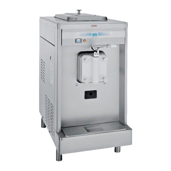
Page 18: Model 741
OPERATOR PARTS IDENTIFICATION Model 741 Figure 4-3 Operator Parts Identification Models 702/741/772... - Page 19 Tray-Drip 14-7/8L X 5-1/8 013690 Tube-Feed-SS-3/16. 028967-3 Shield-Splash 15”L 022763 Panel-Rear 013637 Panel A.-Front X14238-SP Louver-Side-Top 051192 Stud-Nose Cone 022822 Panel-Side Upper R. 028707 Panel-Side Upper L. 028706 Panel A.-Side Lower X24397-SER Adaptor A.-Caster X18915 Operator Parts Identification Models 702/741/772...
-
Page 20: Model 772
OPERATOR PARTS IDENTIFICATION Model 772 Figure 4-4 Operator Parts Identification Models 702/741/772... - Page 21 Panel-Upper Side L. 028700 Panel-Service 046584 Tube-Feed-SS-3/16 028967-3 Shield-Splash 037041 Panel-Rear 017563 Tray-Drip 014533 Louver-Side-Top 051191 Panel A.-Side Left X44853-SER Panel-Upper Side R. 028701 Panel A.-Front X51264 Panel A.-Side Right X44855-SER Stud-Nose Cone 022822 Adaptor A.-Caster X18915 Operator Parts Identification Models 702/741/772...
-
Page 22: Model 741 & 772 Door Assembly
OPERATOR PARTS IDENTIFICATION Model 741 & 772 Door Assembly Figure 4-5 Item Description Part No. Item Description Part No. Seal-Drive Shaft 032560 O-ring 1-1/16 OD X 139 W 084545-SER Shaft-Beater 033498 Cap-Design-1.188” ID 6 PT 013139-6 Beater A.-7 QT. 1 Pin... -
Page 23: Section 5: User Interface
Section 5 Indicator Light—MIX LOW Control Switch The Models 702, 741, and 772 are equipped with a MIX The center position is OFF. The right position is AUTO, LOW light located on the front of the machine. When the which activates the beater motor and the refrigeration light begins to flash, it indicates that the mix hopper has a system. -
Page 24: Thermistor Control
C) to prevent overbeating and product breakdown. ALWAYS FOLLOW LOCAL HEALTH CODES. Cleaning and sanitizing schedules are governed by federal, state, or local regulatory agencies, and must be followed accordingly. If the unit has a Standby mode, it User Interface Models 702/741/772... -
Page 25: Section 6: Operating Procedures
Locate your model number below to determine the characteristics of your freezer. 702: One 4 qt. (3.8 L) freezing cylinder. 741: One 7 qt. (6.6 L) freezing cylinder. 772: Two 7 qt. (6.6 L) freezing cylinders. Figure 6-1 We begin our instructions at the point where we enter the 2. - Page 26 OPERATING PROCEDURES 5. Slide the two O-rings into the grooves on the draw 11547 valve and lubricate them with Taylor Lube. 11103 Figure 6-3 If the blades are in good condition, place the rear Figure 6-5 scraper blade over the rear holding pin on the beater, Lubricate the inside of the freezer door spout, top with the knife edge facing outward.
- Page 27 Figure 6-11 10178 12. Slide the rear drip pan into the hole(s) in the side panel. Figure 6-9 Operating Procedures Models 702/741/772...
-
Page 28: Sanitizing
Failure to follow this cylinder to agitate. Allow the solution to agitate for 5 instruction may result in health hazards. minutes. Operating Procedures Models 702/741/772... -
Page 29: Priming
Important! Failure to remove all sanitizing solution may result in damage to the freezing cylinder. 2. When the mix has stopped bubbling down into the freezing cylinder, install the mix feed tube into the mix inlet hole. Operating Procedures Models 702/741/772... -
Page 30: Closing Procedures
Repeat steps 1 through 5 for the second freezing cylinder on Model 772. rerun, the product must be discarded. Follow the instructions in step 3, except drain the product into a pail and properly discard the mix. Operating Procedures Models 702/741/772... -
Page 31: Disassembly
Make sure all brushes provided with the freezer are available for brush cleaning. 2. Remove the seal(s) from the drive shaft(s). 3. Remove these items from the freezer door(s). • Gasket(s) • Front bearing(s) • Design cap(s) • Draw valve(s) Operating Procedures Models 702/741/772... - Page 32 OPERATING PROCEDURES Notes: Operating Procedures Models 702/741/772...
-
Page 33: Section 7: Operator Checklist
Deteriorated or cracked water lines should be replaced only by an Properly prepare the cleaning and sanitizing authorized Taylor technician. solutions. Read and follow label directions Operator Checklist Models 702/741/772... -
Page 34: Winter Storage
This is extremely important. Failure to follow this procedure may cause severe and costly damage to the refrigeration system. Your local Taylor distributor can perform this service for you. Wrap detachable parts of the freezer such as the beater, blades, drive shaft, and freezer door. -
Page 35: Section 8: Troubleshooting Guide
Rounded corners of drive shaft, a. Call service technician to correct the in the gear box coupling. coupling, or both. cause and replace the necessary components. Do not lubricate the end of the drive shaft. Troubleshooting Guide Models 702/741/772... - Page 36 The handscrews are not tightened. d. Tighten the handscrews equally in a crisscross pattern. e. The beater assembly is rubbing the e. Call service technician to correct the back of the door. problem. Troubleshooting Guide Models 702/741/772...
-
Page 37: Section 9: Parts Replacement Schedule
Minimum 38” necessary. White Bristle Brush, 1-1/2” x Inspect and replace if Minimum 2” necessary. Black Bristle Brush, 1” x 2” Inspect and replace if Minimum necessary. Double-Ended Brush Inspect and replace if Minimum necessary. Parts Replacement Schedule Models 702/741/772... - Page 38 PARTS REPLACEMENT SCHEDULE Notes: Parts Replacement Schedule Models 702/741/772...
-
Page 39: Section 10: Limited Warranty On Equipment
Taylor, through an authorized Taylor distributor or service agency, will provide a new or remanufactured part, at Taylor’s option, to replace the failed defective part at no charge for the part. Except as otherwise stated herein, these are Taylor’s exclusive obligations under this limited warranty for a Product failure. This limited warranty is subject to all provisions, conditions, limitations and exclusions listed below and on the reverse (if any) of this document. - Page 40 LEGAL REMEDIES The owner must notify Taylor in writing by certified or registered letter to the following address of any defect or complaint with the Product, stating the defect or complaint and a specific request for repair, replacement, or other correction of the Product under warranty, mailed at least thirty (30) days before pursuing any legal rights or remedies.
-
Page 41: Section 11: Limited Warranty On Parts
Taylor warrants the Parts against failure due to defect in materials or workmanship under normal use and service as follows. All warranty periods begin on the date of original installation of the Part in the Taylor unit. If a Part fails due to defect during the applicable warranty period, Taylor, through an authorized Taylor distributor or service agency, will provide a new or remanufactured Part, at Taylor’s option, to replace the failed defective Part at no charge for the Part. - Page 42 Taylor. 5. Replacement of wear items designated as Class “000” Parts in the Taylor Operator's Manual, as well as any release sheets and clips for the Product's upper platen assembly.
- Page 43 LEGAL REMEDIES The owner must notify Taylor in writing by certified or registered letter to the following address of any defect or complaint with the Part, stating the defect or complaint and a specific request for repair, replacement, or other correction of the Part under warranty, mailed at least thirty (30) days before pursuing any legal rights or remedies.
- Page 44 LIMITED WARRANTY ON PARTS Notes: 11-4 Limited Warranty on Parts Models 702/741/772...
Need help?
Do you have a question about the 741 and is the answer not in the manual?
Questions and answers