
Related Manuals for Taylor 441


Summary of Contents for Taylor 441
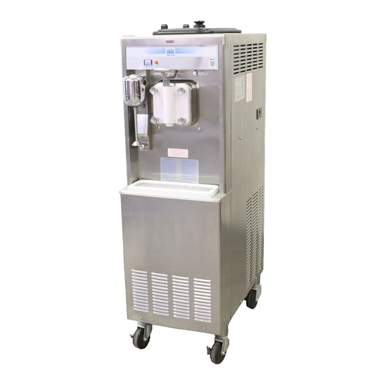
- Page 1 OPERATOR’S MANUAL Model 441 & 444 Shake Freezers Original Operating Instructions 029405- M 6/97 (Original Publication) (Updated 7/1/15)
- Page 2 Complete this page for quick reference when service is required: Taylor Distributor: Address: Phone: Service: Parts: Date of Installation: Information found on the data label: Model Number: Serial Number: Electrical Specs: Voltage Cycle Phase Maximum Fuse Size: Minimum Wire Ampacity: E 1997 Carrier Commercial Refrigeration, Inc.
-
Page 3: Table Of Contents
............Models 441 & 444 Door Assembly . - Page 4 Statutory Damages of up to $250,000 (17 USC 504) for infringement, and may result in further civil and criminal penalties. All rights reserved. Taylor Company a division of Carrier Commercial Refrigeration, Inc. 750 N. Blackhawk Blvd. Rockton, IL 61072 Table of Contents Models 441 & 444...
-
Page 5: To The Installer
Taylor equipment. water jet or hose to rinse or clean the unit. Failure to follow this instruction may result in electrocution. Only authorized Taylor service personnel should perform installation and repairs on the equipment. Authorized service personnel should consult This unit must be installed on a level surface OSHA Standard 29CFRI910.147 or the... - Page 6 If the supply cord is damaged, it must be ampacity, and other electrical specifications. Refer to replaced by an authorized Taylor service the wiring diagram provided inside of the electrical box for proper power connections.
- Page 7 If burns are severe, apply “OFF” position. ice packs and contact a physician immediately. Beater Rotation Taylor reminds technicians to be cautious of Beater rotation must be clockwise as viewed government laws regarding refrigerant recovery, looking into the freezing cylinder.
-
Page 8: To The Operator
Note: Your Taylor warranty is valid only if the parts are label should be used. The unauthorized use of authorized Taylor parts, purchased from the local... -
Page 9: Safety
We, at Taylor Company, are concerned about the safety of the operator at all times when they are coming in contact with the unit and its parts. Taylor makes every effort to design and manufacture built- in DO NOT operate the freezer unless it is safety features to protect both operators and service properly grounded. - Page 10 78 dB(A) when measured at a distance of 1.0 surface. Failure to comply may result in personal injury meter from the surface of the machine and at a height or equipment damage. of 1.6 meters from the floor. 130909 Safety Models 441 & 444...
-
Page 11: Operator Parts Identification
028707- SP Stud- Nose 022822 Panel A.- Side Lower Left X44853 Adaptor A.- Caster X18915 Caster- Swivel- 5/8 Stem 4” Wheel 018794 Panel A.- Side Lower Right X44855 Panel- Side Upper Left 028700 111101 Models 441 & 444 Operator Parts Identification... -
Page 12: Model 444
X44855 Panel- Upper Side Right 028701 Panel A.- Side Left X44853 Caster- 4” Swv 5/8 Stem w/Brake 034081 Adaptor A.- Caster X18915 Panel- Service 024439 Caster- Swivel- 5/8 Stem 4” Wheel 018794 111101 Operator Parts Identification Models 441 & 444... -
Page 13: Models 441 & 444 Door Assembly
Models 441 & 444 Door Assembly Item Description Part No. Item Description Part No. Seal- Drive Shaft 032560 O- Ring 1- 1/16 OD x .139 W 020571 Shaft- Beater 033498 Door A.- 1 Spout 7 Qt. X30272- SER Beater A.- 7 Qt.- 1 Pin Support... -
Page 14: Accessories
Item Description Part No. Item Description Part No. Pail- 10 Qt. 013163 Kit A.- Tune Up (Model 441) X33351 Kit A.- Tune Up (Model 444) X36356 Brush- Mix Pump Body 3 x 7 023316 Lubricant- Taylor 047518 Brush- Double Ended... -
Page 15: Important: To The Operator
Figure 3 Reset Button On the Models 441 and 444, the reset button is located on the lower front panel. Figure 2 The reset button protects the beater motor from an overload condition. -
Page 16: Thermistor Control
2 or 3 times before an accurate consistency mix temperature in the hopper to below 40_F. (4.4_C.) can be evaluated. This assures bacteria control. Important: To the Operator Models 441 & 444... -
Page 17: Operating Procedures
Section 6 Operating Procedures The Model 441 has been selected to show you the pictured step- by- step operating procedures for both models contained in this manual. These models, for practical purposes of operation, are the same. They both store 20 quarts (18.9 liters) of mix in the hopper. - Page 18 Replace any damaged parts. Step 7 Slide the two o- rings into the grooves on the draw valve and lubricate them with Taylor Lube. Figure 8 Note: To prevent costly damage, the hole in the scraper blade must fit securely over the pin.
- Page 19 Lay the mix feed tube and the hopper gasket in the bottom of the mix hopper. Note: Hopper gaskets are not used on the Model 444. Repeat Steps 1 through 12 for the other side of the Figure 12 freezer on the Model 444. Models 441 & 444 Operating Procedures...
-
Page 20: Sanitizing
Allow the solution to agitate for five ATIONS. minutes. Step 2 Pour the sanitizing solution into the hopper and allow it to flow into the freezing cylinder. Figure 16 Figure 18 080924 Operating Procedures Models 441 & 444... -
Page 21: Priming
Figure 20 Repeat Steps 1 through 7 for the other side of the freezer on the Model 444. Figure 22 150701 Models 441 & 444 Operating Procedures... -
Page 22: Closing Procedure
Repeat these steps for the second freezing cylinder on the Model 444. Figure 24 ALWAYS FOLLOW LOCAL HEALTH CODES. Repeat Steps 1 through 5 for the other side of the freezer on the Model 444. 140811 Operating Procedures Models 441 & 444... -
Page 23: Rinsing
“OFF” freezer are available for brush cleaning. position. Step 2 Repeat Steps 1 through 5 for the second freezing cylinder on the Model 444. Remove the seal(s) from the drive shaft(s). 080924 Models 441 & 444 Operating Procedures... - Page 24 Take particular care to brush clean the draw valve core in the freezer door(s). Place all the cleaned parts on a clean dry surface to air dry Step 6 overnight. Wipe clean all exterior surfaces of the freezer. Operating Procedures Models 441 & 444...
-
Page 25: Important: Operator Checklist
8. The temperature of the mix in the mix hopper hole which extends from the mix hopper down and walk- in cooler should be below 40_F. to the rear of the freezing cylinder. (4.4_C.). 080401 Models 441 & 444 Important: Operator Checklist... -
Page 26: Regular Maintenance Checks
5. Using a screwdriver and cloth towel, keep the refrigeration system. rear shell bearing and the female hex drive Your local Taylor Distributor can perform this service socket clean and free of lubricant and mix for you. deposits. -
Page 27: Section 8 Troubleshooting Guide
Product is over beaten. g. Draw off some product to allow fresh product to enter the freezing cylinder. h. Loss of water (W/C) h. Locate cause of water loss and correct. Models 441 & 444 Troubleshooting Guide... - Page 28 Plug into wall receptacle. control switch in AUTO. b. Circuit breaker off or b. Turn circuit breaker on or replace fuse. blown fuse. c. Beater motor out on reset. c. Reset the freezer. 150701 Troubleshooting Guide Models 441 & 444...
- Page 29 Replace the handscrews. damaged. d. Freezer door has d. Replace the door. enlarged holes. e. The beater assembly is e. Call service technician to correct the problem. rubbing the back of the door. Models 441 & 444 Troubleshooting Guide...
-
Page 30: Section 9 Parts Replacement Schedule
White Bristle Brush, 1” x 2” Inspect & Replace Minimum if Necessary Black Bristle Brush, 1” x 2” Inspect & Replace Minimum if Necessary Double- Ended Brush Inspect & Replace Minimum if Necessary Parts Replacement Schedule Models 441 & 444... -
Page 31: Section 10 Limited Warranty On Equipment
Taylor, through an authorized Taylor distributor or service agency, will provide a new or re- manufactured part, at Taylor’s option, to replace the failed defective part at no charge for the part. Except as otherwise stated herein, these are Taylor’s exclusive obligations under this limited warranty for a Product failure. - Page 32 LEGAL REMEDIES The owner must notify Taylor in writing, by certified or registered letter to the following address, of any defect or complaint with the Product, stating the defect or complaint and a specific request for repair, replacement, or other correction of the Product under warranty, mailed at least thirty (30) days before pursuing any legal rights or remedies.
-
Page 33: Section 11 Limited Warranty On Parts
Taylor warrants the Parts against failure due to defect in materials or workmanship under normal use and service as follows. All warranty periods begin on the date of original installation of the Part in the Taylor unit. If a Part fails due to defect during the applicable warranty period, Taylor, through an authorized Taylor distributor or service agency, will provide a new or re- manufactured Part, at Taylor’s option, to replace the failed defective Part at no... - Page 34 Parts or the units in which they are installed repaired or altered in any way so as, in the judgment of Taylor, to adversely affect performance, or normal wear or deterioration.
-
Page 35: Rockton, Il
LEGAL REMEDIES The owner must notify Taylor in writing, by certified or registered letter to the following address, of any defect or complaint with the Part, stating the defect or complaint and a specific request for repair, replacement, or other correction of the Part under warranty, mailed at least thirty (30) days before pursuing any legal rights or remedies.
Need help?
Do you have a question about the 441 and is the answer not in the manual?
Questions and answers