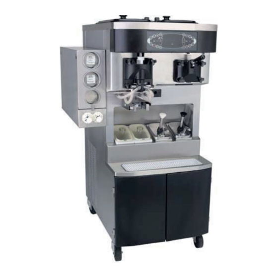
Taylor C602 Service Manual
Combination shake / soft serve freezer
Hide thumbs
Also See for C602:
- Original service instructions (178 pages) ,
- Manual (102 pages) ,
- Pocket manual (92 pages)
Table of Contents
Advertisement
Advertisement
Table of Contents
Troubleshooting

Related Manuals for Taylor C602


Summary of Contents for Taylor C602
- Page 1 Model C602 Combination Shake / Soft Serve Freezer Service Manual 057888-S 4/6/04...
-
Page 2: Table Of Contents
............Model C602 Specifications . - Page 3 ........... . CAUTION: Information in this manual is intended to be used by Taylor Authorized Service Technicians only.
-
Page 4: Section 1: Introduction
Section 1: Introduction Safety Refrigerant Specifications Installation Instructions Model C602 Introduction... -
Page 5: Safety
The many built-in safety features that non-flammable; however, any gas under pressure is are part of all Taylor equipment are aimed at potentially hazardous. protecting operators and trained service technicians alike. - Page 6 Compressor Warranty Disclaimer ______________________________ It should be noted, that Taylor does not warrant the refrigerant used in its equipment. For example, if the refrigerant is lost during the course of ordinary The refrigeration compressor(s) on this machine are service to this machine, Taylor has no obligation to...
-
Page 7: Model C602 Specifications
Model C602 Specifications Freezing Cylinders Electrical Shake Side: One, 7 quart (6.6 liter) Standard is 208/230-60-3; however, other electrical Soft Serve: One, 3.4 quart (3.2 liter) characteristics are available. Each unit requires electrical service - Three Phase Maximum Fuse Size: 40 A, Minimum Wire Ampacity: 36 A Mix Hopper Note: McDonald’s specifies Hubbell A460P9 plug... -
Page 8: Installation Instructions
REMEMBER TO DISCONNECT ALL Note: If the gear unit is out of alignment, refer to POWER TO THE FREEZER! Failure to follow this the General Service Manual. instruction may result in electrocution. Model C602 Introduction... - Page 9 REMEMBER TO DISCONNECT ALL all-pole disconnecting device with a contact gap of at POWER TO THE FREEZER! Failure to follow this instruction may result in electrocution. least 3 mm installed in the external installation. Model C602 Introduction...
-
Page 10: Section 2: Systems, Controls And Operations
Glycol System Glycol Path Setting Viscosity Portion Control (Shake) Control Overview Electrical System Modes of Operation Chart Electrical System - L1 Power Path Shake Draw Sequence Chart Syrup Delivery Syrup Calibration Shake Draw Mechanism Alignment Model C602 Systems, Controls and Operations... -
Page 11: Running Specifications
Suction pressure equals expansion valve setting. The following are the Taylor Company recommended settings for various components in High Side (Discharge) the Model C602. (See page 9 for the Refrigeration High side pressure varies for air cooled units, System Schematic.) depending on the ambient temperature. -
Page 12: Refrigeration System Schematic
Refrigeration System Schematic Figure 2 Model C602 Systems, Controls and Operations... -
Page 13: Control Panel Functions
Indicator Light-Mix Out Illuminates when the mix hopper has an insufficient supply of mix to operate the freezer. The Auto mode will be locked out and the machine will be placed in the Standby mode. Model C602 Systems, Controls and Operations... - Page 14 To better communicate in the International arena, the words on many of our operator keys have been replaced by symbols to indicate their functions. Your = MENU DISPLAY Taylor equipment is designed with these International symbols. The following chart identifies the symbol definitions. = AUTO...
- Page 15 TIMEOUT screen is displayed with the alarm turned switch is in the ON position. (See Figure 8.) on. (See Figure 5.) HOPPERS 21.0 21.1 SAFETY TIMEOUT ANY KEY ABORTS UNIT CLEANED Figure 5 Figure 8 Model C602 Systems, Controls and Operations...
- Page 16 HOT PRODUCT HEAT symbols will no longer be illuminated. The HOT PRODUCT machine will enter the STANDBY mode (STANDBY symbols illuminate). The machine can be Figure 10 placed in AUTO or left in STANDBY. Model C602 Systems, Controls and Operations...
-
Page 17: Freezer Lock-Out
AUTO, the machine will enter the STANDBY mode and display the following message. (See Figure 15.) BRUSH CLEAN TIMEOUT FREEZER LOCKED CLEANING REQ’D WASH TO BRUSH CLEAN FREEZER LOCKED Figure 11 Figure 15 Model C602 Systems, Controls and Operations... - Page 18 Model C602 Systems, Controls and Operations...
- Page 19 HEAT symbol will illuminate Menus. (See page 23.) and the following message will be displayed on the screen. (See Figure 19.) L: DO NOT DRAW R: DO NOT DRAW Figure 19 Model C602 Systems, Controls and Operations...
- Page 20 CURRENT CONDITIONS screen is displayed. The soft serve side will continue operation in the mode it was in when the Menu was selected. However, the soft serve side control keys will not be Figure 24 Model C602 Systems, Controls and Operations...
- Page 21 MIX PUMP OFF DELAY WHITESPOT ADJUST CAL SYRUP TIME SERVINGS COUNTER DRAW SAFETY TIME LEFT RIGHT EDIT UNIT ID CALIBRATE PROXIMITY SWITCH > Next SELECT LANGUAGE ABORT HEAT CYCLE SYRUP MOTOR SETUP Figure 26 Model C602 Systems, Controls and Operations...
- Page 22 Note: Do not advance the Auto Heat Time setting > Exit except on the day the unit is brush cleaned. Increasing the time between heat cycles will cause Figure 29 the machine to soft lock if the start of the cycle does Model C602 Systems, Controls and Operations...
- Page 23 Enable Select the CALIBRATION symbol to return to the previous screen with the new time setting displayed. > Disable Select the CALIBRATION symbol to exit the Figure 34 screen and return to the Menu. Model C602 Systems, Controls and Operations...
- Page 24 Mix Low and Mix Out will intervals by selecting the AUTO symbol illuminate as the mix level drops in the hopper but decrease the days or the OPTIONAL FLAVOR the audible tone will be disabled. Model C602 Systems, Controls and Operations...
- Page 25 NO HEAT CYCLE TRIED - The Auto Heat Time GLYCOL THERMISTOR BAD - Place the power was set to attempt a heat cycle more than 24 hours switch in the OFF position. Replace the bad probe. after the last successful heat cycle. Model C602 Systems, Controls and Operations...
- Page 26 3 displays the total time in each heat cycle phase. (L/R) HPCO H/C - The (left/right) side high pressure Line 4 displays the glycol temperature at the switch opened during the heat treatment cycle. completion of the heat cycle and the page number. Model C602 Systems, Controls and Operations...
- Page 27 Indicates the heat cycle was aborted in the 000.0 000.0 OPERATOR ABORT option in the service PHASE TIME: 00:00 menu. Product Door Not in Place A product door is not in place or is loose. Figure 46 Model C602 Systems, Controls and Operations...
- Page 28 GLYCOL 41.0 machine. (See Figure 47.) Figure 50 SOFTWARE VERSION C602 CONTROL UVC3 VERSION 1.00 CURRENT CONDITIONS is the only Menu screen > Next that will return the left and right side control panel keys to normal operation.
- Page 29 > Next Figure 53 Figure 55 Select the CALIBRATION symbol to save the Select the CALIBRATION symbol to save the setting and return to the Service Menu. setting and return to the Service Menu. Model C602 Systems, Controls and Operations...
- Page 30 Next Figure 57 The GLYCOL HOLDING TEMPERATURE set point Note: A Hedlund (HD) is a Taylor factory defined controls the glycol heater in the HOLDING phase of unit of measure representing the relative product the Heat Treatment Cycle. When the glycol viscosity (thickness).
- Page 31 . (See Figure 64.) The Left Compressor Cycle Time is displayed first. (See Figure 61.) COMP ON DELAY COMP CYCLE TIME RIGHT : 2 SECONDS L CYCLE TIME : 5 MIN Figure 61 Figure 64 Model C602 Systems, Controls and Operations...
- Page 32 OPTIONAL FLAVOR symbol to adjust the setting. The Select the CALIBRATION symbol to save the recommended setting is 10 seconds. (See setting and advance to the Whitespot Setting for the Figure 67.) next flavor. Model C602 Systems, Controls and Operations...
- Page 33 Draw Enter the store number, then select the Safety Time setting or the OPTIONAL FLAVOR CALIBRATION symbol to save the setting and symbol to decrease the setting. Select the return to the Service Menu. Model C602 Systems, Controls and Operations...
- Page 34 (100 - 160) if the flow rate is too slow or the Menu screen and discontinue beater motor amount of syrup measured in the Verification Mode operation. is not within the specified range. Model C602 Systems, Controls and Operations...
- Page 35 (0.26 – 0.32). Examples: (Triple Thick Shake Settings) FLAVOR SPEED REVERSE TIME Chocolate 0.28 - 0.32 Strawberry 0.26 - 0.30 Vanilla 0.25 - 0.28 Optional 0.25 - 0.28 Model C602 Systems, Controls and Operations...
-
Page 36: Heat Treatment Cycle
HEAT phase of the Heat Treatment Cycle. If the that the machine is operating in the STANDBY timer exceeds 90 minutes, the unit will lock-out. mode. Model C602 Systems, Controls and Operations... -
Page 37: Heat Treatment Graph
60 off. The timed cycle continues in this manner until minutes. the COOL phase is complete. Figure 80 Model C602 Systems, Controls and Operations... -
Page 38: Timers
If the machine runs longer than 24 hours without a This pattern continues until hopper refrigeration is no successful Heat Treatment Cycle, the machine will longer required. soft lock. Model C602 Systems, Controls and Operations... - Page 39 Hopper and barrel temperatures are above 60°F phase requirements are met and the total time of the (15.6°C). HEAT and HOLD phases is greater than 115 minutes. c. Both freezer doors were removed concurrently. Model C602 Systems, Controls and Operations...
-
Page 40: Glycol System
(if freezer is in the AUTO, STANDBY or HEAT mode. applicable). The glycol existing in the accumulator The agitator is driven by a motor and belt(s). will be pumped through the glycol system. Model C602 Systems, Controls and Operations... - Page 41 Replace the cap on the accumulator. hose and replace the access cap. Replace the outlet Step 4 line of the glycol pump to proper position. Remove Check for glycol mixture leaks. the pliers. Figure 82 Model C602 Systems, Controls and Operations...
-
Page 42: Glycol Path
Glycol Path (Rear View) Figure 83 Model C602 Systems, Controls and Operations... -
Page 43: Setting Viscosity
4000 HD’s. To adjust the serving viscosity, it may be necessary to raise or lower the HD setting. Adjust in increases of 100 HD’s at a time. Note: Be sure that the syrups are correctly calibrated before determining the proper serving viscosity. Model C602 Systems, Controls and Operations... -
Page 44: Portion Control (Shake)
5 VDC pulse when a cup-full is sensed. Pin 2 = BLACK: This is the DC GROUND connection. Pin 4 = RED: This is the +12 VDC power supply from the interface board. Model C602 Systems, Controls and Operations... -
Page 45: Adjustable Draw Handle
5 to 7-1/2 oz. (142 to 213 g.) of product by weight per 10 seconds. To INCREASE the flow rate, turn the screw CLOCKWISE, and COUNTER- CLOCKWISE to DECREASE the flow rate. (See Figure 85.) Figure 85 Model C602 Systems, Controls and Operations... -
Page 46: Control Overview
Control Overview Figure 86 Model C602 Systems, Controls and Operations... -
Page 47: Universal Control (Uvc3)
See table on page 45. EPROM Chip PLCC Chip-C602 Software Version Number. RAM Chip Stores program settings from menu in memory. Audible Tone Device Not activated on Model C602 (See table on page 45.) Model C602 Systems, Controls and Operations... - Page 48 The pins on the soft serve voltage range for the control is 4.75 – 5.25 VDC. board are inactive in the Model C602. The pins on Note: For installations with low voltage supply the shake interface board function as follows: (210V or less) it may be necessary to wire the 16 VAC transformer on the low voltage tap.
- Page 49 The UVC3 Control calculates the motor speed dial at the top of the board is non-functional. The setting in the syrup calibration mode and sends the VFD does not require a contrast adjustment. information to the speed control. Model C602 Systems, Controls and Operations...
-
Page 50: Electrical System Modes Of Operation Chart
STANDBY WASH AUTO PUMP PRIME Heat Hold Cool Compressor Beater Motor Spinner Motor (Shake Only) Air/Mix Pump Motor Syrup Pump Glycol Heater Agitator Left Glycol Solenoid Right Glycol Solenoid Glycol Pump Shake Draw Solenoid Model C602 Systems, Controls and Operations... -
Page 51: Electrical System - L1 Power Path
1 for the compressor contactor coil. (Compressor pin 5 to supply power to the air/mix pump overload delay start based on COMP ON DELAY setting in and then to the air/mix pump motor. the Service Menu.) Model C602 Systems, Controls and Operations... - Page 52 J6 pin 1 on the interface boards. Once the freezing cylinder and hopper thermistor probes (connected to terminal J10 on the interface board) have been satisfied, the Heat Treatment cycle will end. Model C602 Systems, Controls and Operations...
-
Page 53: Shake Draw Sequence Chart
*Syrup Motor Reverse Timer (0.25 - 0.35) Viscosity Setting Stop Compressor J6-T1 / J7-T7 Achieved Cycle OFF Achieved - Cycle OFF Stop Beater Motor J6-T7 / J7-T1 Start Off Cycle Stir Timer *Adjustable setting in Service Menu Model C602 Systems, Controls and Operations... -
Page 54: Syrup Delivery
AUTO mode, the UVC3 control regulates the motor Refer to the Motor Setup section in the Service speed necessary to dispense syrup at the calibrated Menu, page 31 for motor and reverse time settings. Figure 87 Model C602 Systems, Controls and Operations... -
Page 55: Syrup Calibration
(See Figure 88.) Figure 90 Step 3 Touch the CALIBRATION symbol to enter the syrup calibration mode. (See Figure 91.) SYRUP CALIBRATION Select a Flavor < Press to clear Figure 88 Figure 91 Model C602 Systems, Controls and Operations... - Page 56 4 for the same flavor until the correct syrup the hole plug in the door. Lower the retaining pin to calibration is achieved. (See Figure 93.) secure the plug in place. 23051 Figure 93 Model C602 Systems, Controls and Operations...
-
Page 57: Shake Dispensing Alignment Procedure
The actuator should slide easily into the draw valve slot when the freezer door assembly is installed. (See Figure 97.) Figure 95 ITEM DESCRIPTION ACTUATOR PLATE SPINNER MOTOR BRACKET SOLENOID VALVE SPINNER MOTOR SPINNER COUPLING BUMPER Figure 97 Model C602 Systems, Controls and Operations... - Page 58 The bottom of the draw valve should be located at the top of the product entry port. If the valve is too high or too low, the height of the solenoid will need adjustment. Figure 99 Model C602 Systems, Controls and Operations...
- Page 59 Step 3 Position the coupling so the bottom of the spinner is recessed 1/32” (0.8 mm) or less in the bottom of the door spout. Step 4 Figure 101 Retighten the coupling screw. Model C602 Systems, Controls and Operations...
-
Page 60: Section 3: Troubleshooting
Section 3: Troubleshooting General Troubleshooting Air/Mix Pump System Troubleshooting Peristaltic Syrup System Troubleshooting Shake Dispensing Mechanism Troubleshooting Shake Portion Control Troubleshooting Bacteria Troubleshooting Model C602 Troubleshooting... -
Page 61: General Troubleshooting Guide
5. Liquid line is hot. a. Shortage of refrigerant. a. Repair leak and recharge. 6. Leaking door spout. a. Improper lubrication. a. Lubricate according to instructions in the operator’s manual. b. Worn or nicked o-ring. b. Replace the o-ring. Model C602 Troubleshooting... - Page 62 Lubricate properly. o-rings. c. Wrong type of lubricate being c. Use proper lubricant. Example: used. Taylor Lube High Performance. 10. Product is not being fed into the a. Inadequate mix in the hopper (Mix a. Fill hopper with mix. freezing cylinder.
- Page 63 Replace the necessary box coupling. coupling, or both are rounded. component(s). Do not lubricate the end of the drive shaft. b. Mix and lubricant are collected in b. Brush clean the rear shell bearing the drive coupling. area regularly. Model C602 Troubleshooting...
- Page 64 27. Unit changes modes or shuts a. Faulty connections or a. Replace faulty components. itself off. components. b. Inadequate voltage supply to the b. Check/correct voltage supply to Universal Control. the control (4.75 - 5.75 VDC). Model C602 Troubleshooting...
- Page 65 Faulty blower baffle. d. Repair or replace blower baffle. e. Inadequate AXV settings. e. Set AXV at proper setting. (See “Running Specifications”.) 29. Symbol selection is delayed. a. Defective dec plate. a. Replace dec plate. Model C602 Troubleshooting...
-
Page 66: Air Mix Pump System Troubleshooting
Malfunctioning draw switch. b. Reposition or replace the microswitch. 6. One pump cannot be assembled. a. Soft serve and shake pump parts a. Consult the operator’s manual for are mixed up. correct pump assembly combinations. Model C602 Troubleshooting... -
Page 67: Peristaltic Syrup System Troubleshooting Guide
Adjust the pump motor reverse set too long. time in the Syrup Motor Setup menu. d. Air leak on the intake side of the d. Check the line for air leaks and syrup line/pick up tube. repair it. Model C602 Troubleshooting... - Page 68 Service menu: 5.0 seconds for standard shakes and 7.0 seconds for Triple Thick Shakes. g. The syrup fills the cup too fast to g. Adjust the motor speed setting accurately calibrate. slower in the Syrup Motor Setup menu. Model C602 Troubleshooting...
- Page 69 Install a hole plug in the freezer door. d. The shake temperature is too cold. d. The correct temperature of a finished chocolate shake is 22.5°F (-5.8°C). Model C602 Troubleshooting...
-
Page 70: Shake Dispensing Mechanism Troubleshooting
Adjust the draw safety time in the low. Service Menu. d. Defective hold relay. d. Replace the relay. e. Loose wire connection in the draw e. Check the circuit for power solenoid circuit. interruption and repair it. Model C602 Troubleshooting... - Page 71 Re-align the dispensing of alignment. mechanism. (See page 54.) e. The draw valve is binding in the e. Replace the defective component. freezer door. The solenoid plunger is binding in Replace the solenoid. the coil body. Model C602 Troubleshooting...
-
Page 72: Shake Portion Control Troubleshooting
The syrup calibration is set too c. Calibrate the syrup. low. d. The portion control sensor lens is d. Clean the lens. dirty. Model C602 Troubleshooting... -
Page 73: Bacteria Troubleshooting
3. Worn, damaged, or cracked parts. a. Provide a food grade lubricant (Example: Taylor Lube). b. Inspect o-rings for holes or tears. O-rings, seals and other wear items must be supplied by the freezer company to meet food industry standards. - Page 74 (4.4_C). Storage temperatures above 45_F will allow cell division in as little as one hour. Once the mix is placed in the hopper, covers must be properly installed to maintain adequate refrigeration and to prevent airborne contaminants from entering the mix. Model C602 Troubleshooting...
- Page 75 Notes: Model C602 Troubleshooting...
-
Page 76: Section 4: Parts
Section 4: Parts Warranty Explanation Parts Identification Parts List Wiring Diagrams Model C602 Parts... -
Page 77: Warranty Explanation
CAUTION: Warranty is valid only if required service work is provided by an Authorized Taylor Service Technician. NOTE: Taylor reserves the right to deny warranty claims on equipment or parts if a non-approved refrigerant was installed in the machine, system modifications were performed beyond factory recommendations, or it is determined that the failure was caused by neglect or abuse. - Page 78 Notes: Model C602 Parts...
-
Page 79: Main Exploded View
Main Exploded View Figure 102 Model C602 Parts... - Page 80 HINGE A.-MOTOR*LEFT X25736 PUMP A.-ULTIMATE SYRUP X56015 SPRING-COMP .970 X .115 025707 LINE A.-ACCESS-LOW-LEFT X56160 NUT-5/16-18 MF LOCK 017327 LINE A.-ACCESS-HIGH-LEFT X56130 GROMMET-7/16 X 5/16 SHOCK 016212 BRACKET-TANK-GLYCOL 047585 CAP-RUBBER MOUNT 011844 TANK-GLYCOL 1.5QT-PLASTIC 047314 *NOT SHOWN Model C602 Parts...
- Page 81 O-RING-1/2 OD X .070W 024278 GUARD-RECTIFIER 059482 SPACER-PROBE-ROUND 041347 PCB A.-DUAL BRIDGE RECTIF X59290-SER PROBE A.-MIX OUT-SQ HOLE X41348 RELAY-DPDT 20A-12VDC 077164-02 DEFLECTOR-TORQUE CPLG 054698 BUSHING-SNAP 1-5/16 ID 017008 *NOT SHOWN CHANNEL A.-CONTROL X55975 COMPRESSOR 047520-33F AHA7513ZXF-AH245R Model C602 Parts...
-
Page 82: Syrup Cabinet View
Syrup Cabinet View Figure 103 ITEM DESCRIPTION PART NO. ITEM DESCRIPTION PART NO. SHELF-SYRUP 056016 BLOCK-HINGE 058613 PUMP-PERISTALTIC 052916 BLOCK-HINGE 058614 MOTOR-GEAR 161 RPM 058725 PIN-HINGE 058615 RACK-SYRUP CABINET DOOR 059144 *NOT SHOWN Model C602 Parts... -
Page 83: Mix Pump & Tubes
Mix Pump & Tubes Figure 104 ITEM DESCRIPTION PART NO. ITEM DESCRIPTION PART NO. PUMP-PERISTALTIC 052916 FITTING-PERISTALTIC PUMP 054526 KIT A.-PERISTALTIC PUMP X54978 O-RING 1/2 OD x .070 024278 TUBE FERRULE- .625 ID 053036 Model C602 Parts... -
Page 84: Pump A. - Mix Simplified Shake - X57028-Xx
048632 Piston 053526 O-Ring 1-3/4 008904 O-Ring 2-1/8” OD- Red 020051 Clip-Mix Pump Retainer 044641 Cap-Valve 056873-XX Tube A.-Feed-Hopper Shake X55973 Gasket-Simplified Pump 053527 Ring-Check .120 OD 056524 Adaptor-Mix Inlet Shake-Blue 054944 O-Ring-11/16 OD - Red 016132 Model C602 Parts... -
Page 85: Pump A. - Mix Simplified Soft Serve - X57029-Xx
056874-XX O-Ring 1-3/4 008904 Gasket-Simplified Pump Valve 053527 Clip-Mix Pump Retainer 044641 Adaptor-Mix Inlet Soft Srv-Red 054825 Tube A.-Feed Hopper - Soft Srv X55974 O-Ring - 11/16 OD - Red 016132 Ring-Check .120 OD 056524 Pin-Cotter 044731 Model C602 Parts... -
Page 86: Brush Identification
Figure 107 ITEM DESCRIPTION WHITE BRISTLE - 1/2” x 1/2” WHITE BRISTLE - 3/16” x 1” BLACK BRISTLE - 1/4” x 1-1/4” WHITE BRISTLE - 1/2” x 1” WHITE BRISTLE - 3” x 1/2” Model C602 Parts... -
Page 87: Control Assembly - X55966-33
Control Assembly - X55966-33 Figure 108 Model C602 Parts... - Page 88 RELAY-SPST-30 A-240 V 032607-27 TRANS.-CONT.-32VA 120/200/ 054834 RELAY-MTR START 042007-34 OVERLOAD-TI 044464 TI#4CR-2-645 #2BM-20V9R-KK20 WASHER-#6 SHAKEPROOF 024541 SHIELD-NOISE ELECTRIC 056031 SCREW-6-32X3/8 BIN HD 002201 BEAD-RUBBER 010613-5.5 NUT-6-32 HEX 000927 FILTER-CORCOM 6EH1 040140-001 CAPACITOR-START 037251-34 HARNESS-WIRE 056425- 47-56UF/220T Model C602 Parts...
-
Page 89: Dec Plate Assembly - X55963
Dec Plate Assembly - X55963 Figure 109 ITEM DESCRIPTION PART NO. ITEM DESCRIPTION PART NO. PLATE-DEC 056131 SCREW-6-32 X 3/8 BIN. HD 002201 PCB A.-INTERFACE X55960-SER CABLE-RIBBON-14C-3”L 056864 INSULATOR-PCB-INTERFACE 057168 Model C602 Parts... -
Page 90: Torque Coupling Assembly - X54722
Torque Coupling Assembly - X54722 Model C602 Parts 1 S CREW 039455 2 L ABEL 049285 3 C OUPLI 054724 4 P I TORQ U E CPL G 054725 5 S PRI 039454 6 0 39453 7 C OUPLI T ORQ U E... -
Page 91: Glycol Heater Assembly - X55965-27
HOSE-RUBBER 5/16 ID X 9/16 047340-16 THERMOSTAT-HI LIMIT OPEN 035786 HEATER A.-GLYCOL-4500 X47395-SER SCREW-8-32 X 3/16 SS RHM 017551 ADAPTOR-5/16 FS X 5/16 047958 BARB SCREW-6X3/8 SL HEX W HD 001825 CLAMP-HOSE 35/64 STEPLES 047344 COVER-TERMINAL HEATER 032864 Model C602 Parts... -
Page 92: Sensor Holder Assembly - X55980
ITEM DESCRIPTION PART NO. ITEM DESCRIPTION PART NO. BRACKET A.-SENSOR X56341 HOLDER-MTG-SENSOR 056503 PROBE SCREW-ADJUSTMENT 5/16-18 051574 NUT-5/16-18 LOCK SS 043072 SCREW-10-32 X 9/16 DOG 038981 PCB A.-PYRO X59073-SER SLEEVE-SENSOR-PYROELEC 038982 *NOT INCLUDED W/X55980 SENSOR HOLDER ASSY. Model C602 Parts... -
Page 93: Parts List
Parts List + Available Separately Parts List Model C602... - Page 94 + Available Separately Model C602 Parts List...
- Page 95 + Available Separately Parts List Model C602...
- Page 96 + Available Separately Model C602 Parts List...
- Page 97 + Available Separately Parts List Model C602...
- Page 98 + Available Separately Model C602 Parts List...
- Page 99 + Available Separately Parts List Model C602...
- Page 100 + Available Separately Model C602 Parts List...
- Page 101 + Available Separately Parts List Model C602...
- Page 102 + Available Separately Model C602 Parts List...
- Page 103 + Available Separately Parts List Model C602...
- Page 104 + Available Separately Model C602 Parts List...
- Page 105 + Available Separately Parts List Model C602...
- Page 106 + Available Separately Model C602 Parts List...
- Page 107 + Available Separately Parts List Model C602...
- Page 108 + Available Separately Model C602 Parts List...
- Page 109 + Available Separately Parts List Model C602...
- Page 110 + Available Separately Model C602 Parts List...
- Page 111 + Available Separately Parts List Model C602...
- Page 112 + Available Separately Model C602 Parts List...
-
Page 113: Wiring Diagrams
Model C602 059480-33 Rev. 4/04... - Page 114 Model C602 059480-58 Rev. 4/04...
Need help?
Do you have a question about the C602 and is the answer not in the manual?
Questions and answers