
Related Manuals for Phoenix Mecano DEWERT OKIN DUOMAT 7 HOME


Summary of Contents for Phoenix Mecano DEWERT OKIN DUOMAT 7 HOME
- Page 1 DUOMAT 7 DUOMAT 7+1 DUOMAT 7+2 Installation Instructions (Translation of original installation instructions)
-
Page 3: Foreword
DUOMAT 7 Foreword Foreword Revisions Version Date Changes 12/09 First edition 02/10 Maintenance, software 02/11 Push force 06/12 Second edition 12/12 RoHS, Note, Toggle 11/18 Third edition Disclaimer and exclusion of liability DewertOkin is not responsible for damage resulting from: ... -
Page 4: Notice For Customers In Eu Nations
Foreword DUOMAT 7 Notice for customers in EU nations German Inspection Authority (TÜV SÜD Product Service) testing label The construction of the DUOMAT 7 has been inspected by the German Inspection Authority (TÜV Product Service). The TÜV Product Service also monitors the production of the DUOMAT 7. The official German TÜV Product Service certifies this construction inspection and production monitor- ing. -
Page 5: Table Of Contents
DUOMAT 7 Table of Contents Table of Contents Foreword Revisions Disclaimer and exclusion of liability Contact address Creation of a complete operating instruction manual for the entire end product Notice for customers in EU nations Table of Contents General Configurations About these installation instructions Availability of this document Conventions used... - Page 6 Table of Contents DUOMAT 7 Maintenance Maintenance Cleaning and care Disposal 10.1 Packaging material 10.2 Drive components 10.3 Batteries Declaration of incorporation EU Declaration of Conformity Additional Information 43170 6.0...
-
Page 7: General
DUOMAT 7 General General Configurations The DUOMAT 7 is run in several different configurations. The DUOMAT 7 name, as used here, al- so includes the DUOMAT 7+1 and DUOMAT 7+2 configurations (HOME, CARE, CARE L, HOSP and CARE/HOSP versions). The chapter "Combination Possibilities" includes information about the different device combinations available. -
Page 8: Conventions Used
General DUOMAT 7 Conventions used Notices which do not relate to safety are indicated in these instructions with a triangle: Triangular notice symbol Safety notice explanations WARNING WARNING indicates a hazardous situation which, if not avoided, could result in serious injury or death. -
Page 9: Safety Notices
DUOMAT 7 Safety Notices Safety Notices Proper and intended usage The DUOMAT 7 is meant to be installed in beds. It provides motor adjustment capabilities for movable reclining bed parts. It should be used in conjunction with suitable fittings and mechanics. ... -
Page 10: Safety Notices Within The Installation Instruction And The Operating Instructions For The Entire Machine
Safety Notices DUOMAT 7 The DUOMAT 7 can be used by children of 8 years and older, persons with reduced physical, sen- sory or mental capabilities, or persons with lack of experience or knowledge when they are super- vised or instructed concerning the safe use of the device and when they understand the resulting risks. -
Page 11: Selection And Qualification Of Personnel
DUOMAT 7 Safety Notices Selection and qualification of personnel This drive should only be installed into the end product by someone who has completed training in electronic motor assembly or has equivalent qualifications. You should only install this drive when you are qualified to do so. Otherwise, a properly qualified person should be found for this task. -
Page 12: Product Identification
Safety Notices DUOMAT 7 Product identification 2.5.1 Ratings plate (type label) A ratings plate on each drive specifies the exact name and serial number of the drive. It also states the technical specifications valid for that particular drive. In particular, you will find the maximum push force here. - Page 13 DUOMAT 7 Safety Notices Use in dry rooms only! Protection class II Follow all special disposal instructions! Follow the special assembly instructions! Conformity mark 43170 6.0...
-
Page 14: Combination Possibilities
Combination Possibilities DUOMAT 7 Combination Possibilities The DUOMAT 7 can be combined for use with other single or double drives. The following basic combinations are possible: a DUOMAT 7 with a operating element, a DUOMAT 7+1 as the main drive and a single drive used as a slave drive with a operating element, ... -
Page 15: Description Of Drive
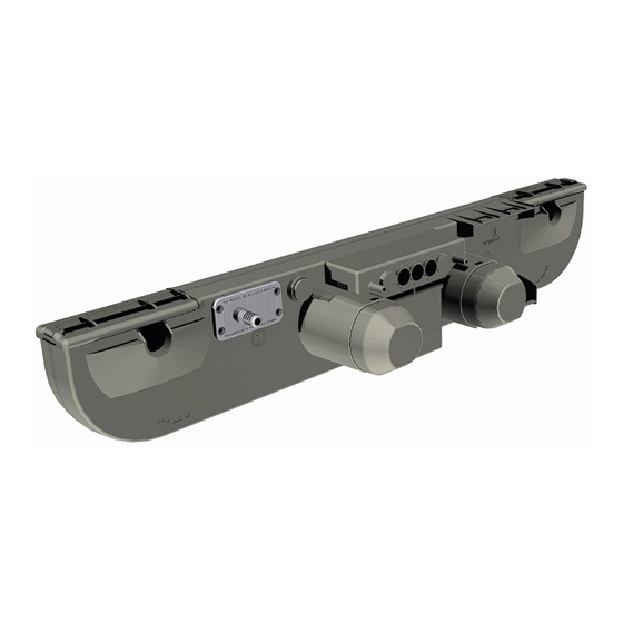
DUOMAT 7 Description of Drive Description of Drive The DUOMAT 7 is an electrically driven motor that is responsible for moving the end product in a linear direction. The head and foot sections of a bed can be adjusted depending on the drive op- tions. - Page 16 Description of Drive DUOMAT 7 Figure 5 Back side of the DUOMAT 7 A DUOMAT 7 without mechanical reset func- B DUOMAT 7 with mechanical reset function tion (on back section) C DUOMAT 7 with mechanical reset function D Lever for operating the mechanical reset (on back and leg sections) function 4.1.1...
-
Page 17: Technical Specifications
DUOMAT 7 Technical Specifications Technical Specifications Connection to mains 100 / 110 / 115 / 120 / 230 / 240 V AC, 50/60 Hz (refer to the ratings plate on drive) Current consumption under rated 0.63 A AC - 3.15 A AC, depending on mains connection load and load (refer to the ratings plate on drive) Permitted push force... - Page 18 Technical Specifications DUOMAT 7 Figure 6 Dimensions of DUOMAT 7 (in mm) Figure 7 Dimensions of DUOMAT 7 (with mechanical reset option) (in mm) 43170 6.0...
-
Page 19: Installation
DUOMAT 7 Installation Installation Safety notices to observe during installation Basic safety rules must be followed in order to ensure that the end product can be continually op- erated in a safe manner. These rules must be observed while using the end product and while in- stalling the drive. -
Page 20: Installation Procedure
Installation DUOMAT 7 Installation procedure 6.2.1 An example installation CAUTION Optional rechargeable battery Disconnect the battery plug from the socket before installation. The battery is con- nected when the drive is delivered. The battery must be unplugged to ensure that the drive does not accidentally activate. - Page 21 DUOMAT 7 Installation 4 Pull out the snapped-in shutters (B) far enough so that the slots (A) are opened up to receive the brackets (D). Abbildung 8 Installing the double drive A Fitting mounts B Shutters 5 Align the DUOMAT 7 next to your product. The slots for the head and foot sides must be proper- ly aligned with the correct brackets on your product (refer to the symbols on the DUOMAT 7 as described in Figure 4).
- Page 22 Installation DUOMAT 7 10 Close off the unused sockets using dummy plugs. The dummy plugs ensure that the sockets are properly protected against any splashed water. 11 Attach the shield cover (as shown in Figure 13). More information is available in the "Connect- ing a rechargeable battery"...
- Page 23 DUOMAT 7 Installation 1 Unplug the mains power plug and the battery plug (when present)! 2 Unscrew the screws (B) on the mains junction box cover (A). 3 Pull the cover (A) gently off of the housing. Be careful not to damage the gasket seal when re- moving the cover.
- Page 24 Installation DUOMAT 7 Optional rechargeable battery (AG7 battery) CAUTION Work on electrical components should be conducted only when the mains power con- nection is unplugged. Connecting the rechargeable battery (AG7 battery) Inserting the battery Battery electrical connection Figure 13 Battery connection for the DUOMAT 7 A Battery B Battery compartment for optional battery C Battery socket...
- Page 25 DUOMAT 7 Installation Taking out the rechargeable battery (AG7 battery) Figure 14 Taking out the battery 1 Remove the shield cover (E) as shown in Figure 13. Disconnect the battery cable from the socket (C). 2 Take the battery out of the DUOMAT 7 battery compartment as shown in Figure 14. Press both battery tabs in until the battery can be pulled out of the compartment.
- Page 26 Installation DUOMAT 7 6.2.3 Dismantling CAUTION Work on electrical components should be carried out only when the mains power and battery plugs (when present) are unplugged. Certain details may change as a result of technical changes. 1 Move your product into a position where it is supporting no load. CAUTION Be sure to carry out work on the drive in a position so that no loads are bearing on it.
-
Page 27: Notices For Operation
DUOMAT 7 Notices for Operation Notices for Operation The factual information contained within may be used when you are creating the end-product man- ual. The installation instructions do not contain all information required for the safe operation of the end product. They only describe the installation and operation of the drive as a partially assembled piece of machinery. -
Page 28: Notice For Operating With Optional Configuration
Notices for Operation DUOMAT 7 Avoiding cable damage Be sure that your operating instructions inform the user about the possible cable risks. CAUTION The cables (particularly the mains cable) should not be run over. In order to prevent injuries or drive damage, no mechanical strain should be placed on the cables. Notice for operating with optional configuration 7.2.1 Optional rechargeable battery (AG7 battery) - Page 29 DUOMAT 7 Notices for Operation 7.2.2 Optional mechanical reset option Figure 15 Back side of the DUOMAT 7, with mechanical reset function A Lever for operating the mechanical reset B Label for mechanical reset function function (on back section) C Lever for operating the mechanical reset function (on leg section) CAUTION The mechanical reset function is not a safety system and does not avert danger.
- Page 30 Notices for Operation DUOMAT 7 7.2.3 Optional operating signals An additional feature is available only for the CARE and HOSP models: an LED illuminates when buttons are pressed and a signal tone sounds when the button is released. ...
-
Page 31: Troubleshooting
DUOMAT 7 Troubleshooting Troubleshooting This chapter describes troubleshooting methods for fixing problems. If you experience an error that is not listed in this table, please contact your supplier. CAUTION Only qualified specialists who have received electrician training should carry out trou- bleshooting and repairs. - Page 32 Troubleshooting DUOMAT 7 Signal tone Meaning Measure / Action Warning tone when the The battery is discharged and has Recharge the battery handset is used. switched off. completely. A continuous alarm tone can The drive is broken. Please contact your sup- be heard.* plier or sales agent.
-
Page 33: Maintenance
DUOMAT 7 Maintenance Maintenance You should only use spare parts which have been manufactured or approved by DewertOkin. Only these parts will guarantee a sufficient level of safety. Maintenance Type of check Explanation Time interval Check the function and safe- A qualified electrician should carry Periodic inspections can ty of the electrical system. -
Page 34: Cleaning And Care
Maintenance DUOMAT 7 Cleaning and care The DUOMAT 7 was designed so that it would be easy to clean. Its smooth surfaces can be con- veniently cleaned. NOTICE Never clean the drive in an automated washing system or with a high-pressure cleaner. Do not allow fluids to penetrate the drive. -
Page 35: 10. Disposal
DUOMAT 7 Disposal 10. Disposal 10.1 Packaging material The packaging material should be sorted into recyclable components and then disposed of in ac- cordance with the appropriate national environmental regulations (in Germany according to the re- cycling law KrWG from 01.06.2012; internationally according to the EU Directive 2008/98/EC (Was- te Framework Directive WFD as of 12.12.2008)). -
Page 36: Declaration Of Incorporation
Declaration of Incorporation Einbauerklärung nach Anhang II der EU-Maschinenrichtlinie According to Appendix II of the EU Machinery 2006/42/EG Directive 2006/42/EC Der Hersteller The manufacturer: DewertOkin GmbH Weststraße 1 32278 Kirchlengern Deutschland - Germany erklärt hiermit, dass nachstehend beschriebene declares that the incomplete machines described unvollständigen Maschinen below DUOMAT 7... -
Page 37: Eu Declaration Of Conformity
EU Declaration of Conformity EG-Konformitätserklärung Nach Anhang IV der EMV-Richtlinie 2014/30/EU In compliance with Appendix IV of the EMC- Directive 2014/30/EU Nach Anhang IV der EU- In compliance with Appendix IV of the LVD- Niederspannungsrichtlinie 2014/35/EU Directive 2014/35/EU Nach Anhang VI der RoHS-Richtlinie In compliance with Appendix VI of the EU RoHS Directive 2011/65/EU 2011/65/EU... -
Page 38: Additional Information
Additional information DUOMAT 7 The following standards and norms were used in the versions with at least IPX4 and higher - in according to: EN 60601-1:2006 + A1:2013, IEC 60601-1:2005 + A1:2012 (short description: Edition 3.1), Medical electrical equipment. EN 60601-1-2:2015, IEC 60601-1-2:2014 (short description: Edition 4.0), EMC IEC/EN60601-1, Section 4 General requirements IEC/EN60601-1, Section 6... - Page 39 Additional information DUOMAT 7 The following standards and norms were used in the versions with at least IPX4 and higher - in according to: EN 60601-2-52, IEC 60601-2-52, (Particular requirements for the safety and essential performance of medical beds) IEC/EN 60601-2-52, Section 201.6.2 Protection against electrical shock: Protection class II IEC/EN 60601-2-52, Section Control panel symbols (depending on model, customer...
- Page 44 DewertOkin GmbH Weststraße 1 32278 Kirchlengern, Germany Tel: +49 (0)5223/979-0 Fax: +49 (0)5223/75182 http://www.dewertokin.de Info@dewertokin.de ID No.: 43170...
Need help?
Do you have a question about the DEWERT OKIN DUOMAT 7 HOME and is the answer not in the manual?
Questions and answers