
Related Manuals for iWave i.MX6 Qseven PMIC SOM


Summary of Contents for iWave i.MX6 Qseven PMIC SOM
-
Page 1: Hardware User Guide
Qseven PMIC SOM Hardware User Guide iW-RainboW-G15M i.MX6 Qseven PMIC SOM Hardware User Guide REL 1.2 iWave Systems Technologies Pvt. Ltd. Page 1 of 82... - Page 2 If you are not the intended recipient (or authorized to receive for the recipient), you are hereby notified that any disclosure, copying distribution or use of any of the information contained within this document is STRICTLY PROHIBITED. Thank you. “iWave Systems Tech. Pvt. Ltd.” REL 1.2 iWave Systems Technologies Pvt.
- Page 3 (including liability to any person by reason of negligence) will be accepted by iWave Systems, its subsidiaries or employees for any direct or indirect loss or damage caused by omissions from or inaccuracies in this document.
-
Page 4: Table Of Contents
Terminlogy Description ............................. 9 References ................................ 9 Important Note ............................... 10 ARCHITECTURE AND DESIGN ........................11 i.MX6 Qseven PMIC SOM Block Diagram ......................11 i.MX6 Qseven PMIC SOM Features ......................... 12 i.MX6 CPU ............................... 14 PMIC ................................15 Boot Switches ..............................15 2.5.1 Boot Mode Switch ............................ - Page 5 3.3.2 Guidelines to insert the Qseven SOM into Carrier board ................73 ORDERING INFORMATION .......................... 74 MIGRATION INFORMATION ........................78 APPENDIX I ..............................80 i.MX6 Qseven PMIC SOM Silk Screen ......................80 APPENDIX II ..............................82 i.MX6 Qseven PMIC SOM Development Platform ..................82 REL 1.2 iWave Systems Technologies Pvt.
- Page 6 Table 17: Power Consumption¹ ............................68 Table 18: Environmental Specification ........................... 69 Table 19: Orderable Product Part Numbers ........................74 Table 20: Differences between i.MX6 Qseven Non PMIC SOM and i.MX6 Qseven PMIC SOM ........78 REL 1.2 iWave Systems Technologies Pvt. Ltd.
-
Page 7: Introduction
This document is the Hardware User Guide for the i.MX6 Qseven System On Module based on the Freescale’s i.MX6 Applications Processor with PMIC. This board is fully supported by iWave Systems Technologies Pvt. Ltd. This Guide provides detailed information on the overall design and usage of the i.MX6 Qseven System On Module from a Hardware Systems perspective. - Page 8 Qseven PMIC SOM Hardware User Guide Acronyms Abbreviations HDMI High-Definition Multimedia Interface Inter-Integrated Circuit Integrated Circuit Image Processing Unit JTAG Joint Test Action Group Kbps Kilobits per second Liquid Crystal Display LVDS Display Bridge LVDS Low Voltage Differential Signal...
-
Page 9: Terminlogy Description
Qseven PMIC SOM Hardware User Guide Terminlogy Description In this document, wherever Signal Type is mentioned, below terminology is used. Table 2: Terminology Terminology Description Input Signal Output Signal Bidirectional Input/output Signal CMOS Complementary Metal Oxide Semiconductor Signal LVDS... -
Page 10: Important Note
Qseven PMIC SOM Hardware User Guide Important Note In this document, wherever i.MX6 CPU signal name is mentioned, it is followed as per below format. If CPU pin functionality name and CPU pad name is same, Signal name is mentioned as “CPU Pad Name”... -
Page 11: Architecture And Design
Qseven PMIC SOM Hardware User Guide 2. ARCHITECTURE AND DESIGN This section provides detailed information about the i.MX6 Qseven PMIC SOM Features and Hardware architecture with high level block diagram. Also this section provides detailed information about Qseven edge connector &... -
Page 12: I.mx6 Qseven Pmic Som Features
Qseven PMIC SOM Hardware User Guide i.MX6 Qseven PMIC SOM Features The i.MX6 Qseven PMIC SOM supports the following features. Freescale’s i.MX6 QuadPlus/Quad/DualPlus/Dual/Duallite/Solo ARM™ Cortex-A9 based CPU @ up to 1GHz/Core PMIC Freescale’s MMPF0100 PMIC Boot Switches ... - Page 13 Qseven PMIC SOM Hardware User Guide SPI x 1 Port (with 2 Chip selects ) CAN x 1 Port Power control & Management signal PWM x 1 Port WDOG I2C x 2 Ports ...
-
Page 14: I.mx6 Cpu
Qseven PMIC SOM Hardware User Guide i.MX6 CPU i.MX6 Qseven PMIC SOM is based on Freescale’s i.MX6 QuadPlus/Quad/DualPlus/Dual/Duallite/Solo ARM™ Cortex- A9 core based CPU which can operate up to 1 GHz speed/core. i.MX6 CPU is Freescale’s latest achievement in integrated multimedia application processors which is part of growing multimedia-focused products that offers high performance processing and are optimized for lowest power consumption. -
Page 15: Pmic
BOOT_MODE [1:0] as well as the state of various eFUSEs and/or GPIO settings to determine the boot flow behaviour of the device. i.MX6 Qseven PMIC SOM supports two Boot switches for selecting Boot Mode setting and Boot Media setting of i.MX6 CPU. -
Page 16: Boot Mode Switch
2.5.1 Boot Mode Switch i.MX6 Qseven PMIC SOM supports two positions Boot Mode Switch (SW2) which is physically located in the top of the PCB. This switch is used to select the boot mode setting of i.MX6 CPU as explained in the below table. -
Page 17: Boot Media Setting Switch
2.5.2 Boot Media Setting Switch i.MX6 Qseven PMIC SOM supports eight positions Boot Media Switch (SW1) which is physically located in the top of the PCB. This switch is used to select the boot media of i.MX6 CPU if i.MX6 CPU boot mode is selected as Internal Boot Mode. -
Page 18: Memory
2.6.4 Micro SD Slot i.MX6 Qseven PMIC SOM supports Micro SD slot to connect Micro SD card for Mass storage and also can be used as Boot device. Micro SD Card Connector (J2) is directly connected to the uSDHC3 of the i.MX6 CPU. It supports card detect feature. -
Page 19: Qseven Pcb Edge Connector
Qseven PMIC SOM Hardware User Guide Qseven PCB Edge Connector Qseven PCB edge connector has standard pin out as per Qseven Specification 2.0. The interfaces which are available at 230pin Qseven Edge connector are explained in the following sections. -
Page 20: Pcie Interface
2.7.1 PCIe Interface i.MX6 Qseven PMIC SOM supports one PCI Express Gen2.0 lane on Qseven Edge connector. i.MX6 CPU’s PCIe Express core with integrated PHY is used for PCIe Interface which can support PCIe Gen2.0 at 5Gbps data rate and are backward compatible to Gen1.1 at 2.5Gbps data rate. -
Page 21: Sata Interface
2.7.4 SATA Interface i.MX6 Qseven PMIC SOM supports one SATA II lane on Qseven Edge connector. i.MX6 CPU’s SATA controller core with integrated PHY is used for SATA Interface which can support SATA II with transfer rate of 3Gbps and backward compatible to SATA I with transfer rate of 1.5Gbps. -
Page 22: Usb 2.0 Otg Interface
2.7.6 USB 2.0 OTG Interface i.MX6 Qseven PMIC SOM supports one USB2.0 OTG interface on Qseven Edge connector. i.MX6 CPU’s USB2.0 OTG controller core with integrated PHY is used for OTG interface which can operate in High Speed operation (480 Mbps), Full Speed operation (12Mbps) and Low Speed operation (1.5 Mbps). -
Page 23: Lvds Display Interface
(including Parallel RGB, HDMI & MIPI DSI) can be supported. 2.7.10 HDMI Interface i.MX6 Qseven PMIC SOM supports one HDMI display port (Ver. 1.4) on Qseven Edge connector. HDMI is a compact audio/video interface for transmitting uncompressed digital video data and uncompressed/compressed digital audio data. -
Page 24: Lpc/Gpio Interface
GPIO with interrupt capable (if not used as other interface). 2.7.12 SPI Interface i.MX6 Qseven PMIC SOM supports one SPI interface with two chip selects on Qseven Edge connector. i.MX6 CPU’s eCSPI2 is used for SPI interface which supports full-duplex synchronous four-wire serial interface with DMA. It supports 32bit x 64 entry FIFO for both transmit and receive data. -
Page 25: Power Input
RSTBTN# input from Qseven Edge connector is the active low signal which is connected to i.MX6 CPU’s POR pin in i.MX6 Qseven PMIC SOM. This pin can be used to reset the i.MX6 CPU by connecting push button in the carrier board. -
Page 26: Pwm Interface
As per Qseven Specification version 2.0, manufacturing signals on Qseven Edge connector can be assigned by vendor and it can be connected to interfaces like UART or JTAG. i.MX6 Qseven PMIC SOM supports one Debug UART interface on these pins in Qseven Edge connector. i.MX6 CPU’s UART2 controller is used for Debug UART interface. -
Page 27: Table 5: 230-Pin Pcb Edge Connector Pin Assignment
Qseven PMIC SOM Hardware User Guide Table 5: 230-Pin PCB Edge Connector Pin Assignment Qseven Edge i.MX6 Ball Signal Type/ Connector Signal Name Name/ Description Termination Pin Name Pin Number Power Ground. Power Ground. GBE_MDI3- GPHY_DTXRXM IO, DIFF Gigabit Ethernet MDI differential pair 3 negative. - Page 28 Qseven PMIC SOM Hardware User Guide Qseven Edge i.MX6 Ball Signal Type/ Connector Signal Name Name/ Description Termination Pin Name Pin Number SUS_S5# GPIO5_0_SUS_S EIM_WAIT/ O, 3.3V CMOS/ S5 state is not supported. ¹ 14.7K PD EIM_WAIT is connected to this...
- Page 29 Qseven PMIC SOM Hardware User Guide Qseven Edge i.MX6 Ball Signal Type/ Connector Signal Name Name/ Description Termination Pin Name Pin Number BATLOW# GPIO3_23_BATL EIM_D23/ I, 3.3V CMOS Battery low input. OW(EIM_D23) Note: EIM_D23 is connected to this pin as GPIO for implementing...
- Page 30 Qseven PMIC SOM Hardware User Guide Qseven Edge i.MX6 Ball Signal Type/ Connector Signal Name Name/ Description Termination Pin Name Pin Number SDIO_CMD SD1_CMD SD1_CMD/ IO, 3.3V CMOS SD1 command. SDIO_WP GPIO6_11_SD1_ NANDF_CS0/ I, 3.3V CMOS SD1 write Protect.
- Page 31 Qseven PMIC SOM Hardware User Guide Qseven Edge i.MX6 Ball Signal Type/ Connector Signal Name Name/ Description Termination Pin Name Pin Number HDA_RST#/ GPIO1_11_HDA SD2_CMD/ O, 3.3V CMOS Audio codec reset. I2S_RST# _RST(SD2_CMD) Note: SD2_CMD signal connected to this pin as GPIO for implementing Audio codec reset.
- Page 32 Qseven PMIC SOM Hardware User Guide Qseven Edge i.MX6 Ball Signal Type/ Connector Signal Name Name/ Description Termination Pin Name Pin Number WDOUT WDOG_B(GPIO_ O, 3.3V CMOS Watchdog event indicator. Note: GPIO_9 is connected to this pin through inverter.
- Page 33 Qseven PMIC SOM Hardware User Guide Qseven Edge i.MX6 Ball Signal Type/ Connector Signal Name Name/ Description Termination Pin Name Pin Number USB_CC GPIO2_25_USB_ EIM_OE/ I, 3.3V CMOS USB client connect. CC(EIM_OE) Note: EIM_OE is connected to this pin as GPIO for implementing USB client connect if required.
- Page 34 Qseven PMIC SOM Hardware User Guide Qseven Edge i.MX6 Ball Signal Type/ Connector Signal Name Name/ Description Termination Pin Name Pin Number LVDS_PPEN GPIO2_4_LVDS_ NANDF_D4/ O, 3.3V CMOS Controls LVDS LCD panel power PPEN(NANDF_D enable. Note: NANDF_D4 signal connected to this pin as GPIO for...
- Page 35 Qseven PMIC SOM Hardware User Guide Qseven Edge i.MX6 Ball Signal Type/ Connector Signal Name Name/ Description Termination Pin Name Pin Number GP_1- HDMI_CEC(EIM EIM_A25/ IO, 3.3V CMOS HDMI CEC bus. Wire_Bus _A25) Note: Same signal is optionally connected...
- Page 36 Qseven PMIC SOM Hardware User Guide Qseven Edge i.MX6 Ball Signal Type/ Connector Signal Name Name/ Description Termination Pin Name Pin Number DP_LANE1-/ HDMI_D1M HDMI_D1M/ O, TMDS HDMI differential data lane 1 TMDS_LANE negative. DP_AUX- Power Ground. Power Ground.
- Page 37 Qseven PMIC SOM Hardware User Guide Qseven Edge i.MX6 Ball Signal Type/ Connector Signal Name Name/ Description Termination Pin Name Pin Number PCIE_WAKE# GPIO2_6_PCIe_ NANDF_D6/ I, 3.3V CMOS PCIe wake event. WAKE(NANDF_ Note: NANDF_D6 is connected to this pin as GPIO for implementing PCIe wake event if required.
- Page 38 Qseven PMIC SOM Hardware User Guide Qseven Edge i.MX6 Ball Signal Type/ Connector Signal Name Name/ Description Termination Pin Name Pin Number UART0_RX UART5_RXD(KEY KEY_ROW1/ I, 3.3V CMOS UART5 serial data receiver. _ROW1) Note: Same signal is optionally connected...
- Page 39 Qseven PMIC SOM Hardware User Guide Qseven Edge i.MX6 Ball Signal Type/ Connector Signal Name Name/ Description Termination Pin Name Pin Number 188 LPC_AD3/ GPIO7_13_Q7_ GPIO_18/ IO, 3.3V CMOS General purpose input/output 3. GPIO3 GPIO3(GPIO_18) Note: Same signal is optionally...
- Page 40 Qseven PMIC SOM Hardware User Guide Qseven Edge i.MX6 Ball Signal Type/ Connector Signal Name Name/ Description Termination Pin Name Pin Number 196 FAN_PWMO Default NC. Note: GPIO_1 optionally GP_PWM_O connected to this pin (for PWM2) through resistor and default not populated.
- Page 41 Qseven PMIC SOM Hardware User Guide Qseven Edge i.MX6 Ball Signal Type/ Connector Signal Name Name/ Description Termination Pin Name Pin Number 209 MFG_NC1 UART2_TXD(EI JTAG_TDO/ O, 3.3V CMOS Serial data transmitter for debug. M_D26) EIM_D26 is connected to this pin through resistor (for UART2_TXD) and default populated.
-
Page 42: Expansion Connector1 Interfaces
Qseven PMIC SOM Hardware User Guide Expansion Connector1 Interfaces Qseven edge connector pull-out only a selected set of interfaces as per Qseven standard. All effort is made in i.MX6 Qseven PMIC SOM design, to provide maximum interfaces of i.MX6 CPU to the carrier board by adding two 80Pin Expansion connectors. -
Page 43: Parallel Lcd Display Interface
2.8.2 MIPI DSI Interface i.MX6 Qseven PMIC SOM supports dual lane MIPI DSI interface (excluding clock lane) @ 1Gbps on Expansion connector1. i.MX6 CPU’s IPU with MIPI DSI Host controller & MIPI D-PHY is used for MIPI DSI interface. It is compliant with MIPI Alliance Specification for Display Serial Interface (DSI), Version 1.01.00 - 21 February 2008 with... -
Page 44: Esai Interface
Qseven PMIC SOM Hardware User Guide 2.8.4 ESAI Interface i.MX6 Qseven PMIC SOM supports one ESAI interface on Expansion connector1. i.MX6 CPU’s ESAI module is used for ESAI interface which provides a full-duplex serial port for serial communication with a variety of serial devices, including industry-standard codecs, SPDIF transceivers and other DSPs. -
Page 45: Table 6: Expansion Connector1 Pin Assignment
Qseven PMIC SOM Hardware User Guide Table 6: Expansion Connector1 Pin Assignment i.MX6 Signal Type/ Signal Name Ball Name/ Description Termination Pin Number Power Ground. DISP0_DAT23 DISP0_DAT23/ O, 3.3V CMOS Parallel LCD data 23 (Red data 7). Default NC. - Page 46 Qseven PMIC SOM Hardware User Guide i.MX6 Signal Type/ Signal Name Ball Name/ Description Termination Pin Number Default NC. Note: GPIO_18 is optionally connected to this pin (for ESAI_TX1) through resistor and default not populated. Note: Same signal is connected to...
- Page 47 Qseven PMIC SOM Hardware User Guide i.MX6 Signal Type/ Signal Name Ball Name/ Description Termination Pin Number Default NC. Note: GPIO_1 is optionally connected to this pin (for PWM2) through resistor and default not populated. Note: Same signal is connected to Qseven edge connector 123 , 194th &...
- Page 48 Qseven PMIC SOM Hardware User Guide i.MX6 Signal Type/ Signal Name Ball Name/ Description Termination Pin Number DISP0_DAT11/ O, 3.3V CMOS Parallel LCD data 11 (Green data3). DISP0_DAT11 Power Ground. DISP0_DAT6 DISP0_DAT6/ O, 3.3V CMOS Parallel LCD data 6 (Blue data6).
- Page 49 Qseven PMIC SOM Hardware User Guide i.MX6 Signal Type/ Signal Name Ball Name/ Description Termination Pin Number SD3_RST/ I, 3.3V CMOS UART3 ready to send data. UART3_RTS(SD3_RST) UART3_CTS(EIM_D30) EIM_D30/ O, 3.3V CMOS UART3 ready to receive data. UART3_TXD(EIM_D24) EIM_D24/ O, 3.3V CMOS...
- Page 50 Qseven PMIC SOM Hardware User Guide i.MX6 Signal Type/ Signal Name Ball Name/ Description Termination Pin Number Default NC. Note: KEY_ROW4 optionally connected to this pin (for CAN2_RX) through resistor and default not populated. Note: Same signal is connected to...
-
Page 51: Expansion Connector2 Interfaces
Qseven PMIC SOM Hardware User Guide Expansion Connector2 Interfaces i.MX6 Qseven PMIC SOM supports Expansion connector2 also to pull out more interfaces of i.MX6 CPU to carrier board. The interfaces which are available at 80pin Expansion connector2 are listed in the following sections. -
Page 52: Parallel Camera Interface2
Note: i.MX6 Duallite and i.MX6 Solo CPU supports only one IPU. 2.9.2 MIPI CSI Interface i.MX6 Qseven PMIC SOM supports four data lane MIPI CSI interface (excluding clock lane) from 80 Mbps up to 1 Gbps speed per data lane on Expansion connector2. i.MX6 QuadPlus/Quad/DualPlus/Dual CPU has two IPU block and each IPU has two input ports CSI0 and CSI1 which can receive data concurrently and independently. -
Page 53: Memory Bus Interface
Qseven PMIC SOM Hardware User Guide 2.9.3 Memory Bus Interface i.MX6 Qseven PMIC SOM supports one memory interface on Expansion connector2. i.MX6 CPU’s EIM module is used for Memory interface which handles the interface to devices external to the chip including generation of chip selects, clock and control for external peripherals and memory. -
Page 54: Table 7: Expansion Connector2 Pin Assignment
Qseven PMIC SOM Hardware User Guide Table 7: Expansion Connector2 Pin Assignment i.MX6 Ball Signal Type/ Signal Name Name/ Description Termination Pin Number MLBDAT(GPIO_2) GPIO_2/ IO,3.3V CMOS MLB single ended data. Note: MLB differential data negative (MLB_DN) is optionally connected to this pin through resistor and default not populated. - Page 55 Qseven PMIC SOM Hardware User Guide i.MX6 Ball Signal Type/ Signal Name Name/ Description Termination Pin Number GPIO_5/ O, 3.3V CMOS KEY_ROW7(GPIO_5) Keypad row 7. Default NC. Note: KEY_COL1 optionally connected to this pin (for KEY_COL1) through resistor and default not populated.
- Page 56 Qseven PMIC SOM Hardware User Guide i.MX6 Ball Signal Type/ Signal Name Name/ Description Termination Pin Number EIM_DA10/ IO, 3.3V CMOS/ EIM_DA10¹ EIM data & address line 10. 14.7K PD EIM_DA13¹ EIM_DA13/ IO, 3.3V CMOS/ EIM data & address line 13.
- Page 57 Qseven PMIC SOM Hardware User Guide i.MX6 Ball Signal Type/ Signal Name Name/ Description Termination Pin Number DI0_PIN2 DI0_PIN2/ O, 3.3V CMOS Parallel LCD HSYNC. Note: If Parallel LCD is not used, this pin can be configured as AUD6_TXD.
- Page 58 Qseven PMIC SOM Hardware User Guide i.MX6 Ball Signal Type/ Signal Name Name/ Description Termination Pin Number Default NC. Note: EIM_A25 is optionally connected to this pin (for HDMI_CEC) through resistor and default not populated. Note: Same signal is connected to...
- Page 59 Qseven PMIC SOM Hardware User Guide i.MX6 Ball Signal Type/ Signal Name Name/ Description Termination Pin Number CSI_D2P/ I, DIFF MIPI CSI differential data lane 2 CSI_D2P positive. CLK2_p CLK2_p/ I, DIFF General purpose high speed differential clock 2 positive.
-
Page 60: Optional Features
2.10.1 NAND Flash i.MX6 Qseven PMIC SOM supports NAND flash memory as mass storage and also can be used as boot device. This is connected to NAND flash controller of the i.MX6 CPU and operates at 3.3 voltage level. This is the optional feature and will not be populated in default configuration. -
Page 61: Pmic Otp Header
2.10.3 PMIC OTP Header i.MX6 Qseven PMIC SOM supports 4Pin PMIC OTP header for PMIC OTP fuse programming. PMIC OTP Header is physically located on topside of the SOM. This is the optional feature and will not be populated in default configuration. -
Page 62: Jtag Header
2.10.4 JTAG Header A customized 20-pin ARM JTAG connector is available in i.MX6 Qseven PMIC SOM for Debug purpose. 3.3V reference power is provided to pin 1 of the connector to allow JTAG tool to automatically configure the logic signals for the right voltage. -
Page 63: Table 10: Jtag Header - Bom
CAP CER 0.1UF 10V 10% X5R CC0402KRX5R6BB104 0402 CONN HEADER .050" 20PS DL PCB LPPB102CFFN-RC Mating connector Note: For i.MX6 Qseven PMIC SOM Silkscreen identifier details, refer APPENDIX I. REL 1.2 iWave Systems Technologies Pvt. Ltd. Page 63 of 82... -
Page 64: Debug Uart Header
2.10.5 Debug UART Header i.MX6 Qseven PMIC SOM supports 3pin UART2 header (J1) for Debug purpose. This UART header supports only serial data input and serial data output signals in RS232 level. This 3-Pin debug UART header is physically located on topside of the SOM. -
Page 65: Power In Connector
2.10.6 Power IN Connector i.MX6 Qseven PMIC SOM works with +5V power input from Qseven Edge connector. Optionally SOM can be powered up using Power IN Header (P1) for standalone purpose. This is the optional feature and will not be populated in default configuration. -
Page 66: Technical Specification
±20 mV ¹ i.MX6 Qseven PMIC SOM is designed to work with VCC input power rail from Qseven Edge connector. Optionally we can use On-SOM Power In connector to feed VCC which can be used only for standalone power up. -
Page 67: Power Input Sequencing
Qseven PMIC SOM Hardware User Guide 3.1.2 Power Input Sequencing i.MX6 Qseven PMIC SOM’s Power Input sequence requirement is explained below. Power up Sequence: VCC_RTC must come up at the same time or before VCC comes up. ... -
Page 68: Power Consumption
RTC power when no VCC supply is provided VCC_RTC 275uA³ ¹ Power consumption measurements have been done in iWave’s i.MX6 Quad CPU based Qseven PMIC SOM (iW- G15M-Q704-3D001G-E004G-LID) with iWave’s Generic Qseven Carrier board running iWave’s Linux3.10 BSP (iW- PRDVZ-RN-01-R5.0-REL1.0-Linux3.10). -
Page 69: Environmental Characteristics
Heat spreader has to be used with application specific thermal solutions like heat sinks, Chassis, fans, Heat pipes etc. iWave supports Heat Spreader Solution for i.MX6 Qseven PMIC SOM. Please refer the below figure for Heat spreader dimension details. For Heat spreader ordering information, please refer section 4 ORDERING INFORMATION. -
Page 70: Rohs Compliance
3.2.4 Electrostatic Discharge iWave’s i.MX6 Qseven PMIC SOM is sensitive to electro static discharge and so high voltages caused by static electricity could damage some of the devices on board. It is packed with necessary protection while shipping. Do not open or use the SOM except at an electrostatic free workstation. -
Page 71: Mechanical Characteristics
3.3.1 Qseven SOM Mechanical Dimensions i.MX6 Qseven PMIC SOM is fully compatible with Qseven specification Revision 2.0.The size of the PCB will be 70 mm x 70 mm x 1.2mm as per Qseven Specification. Qseven SOM mechanical dimension is shown below. Please refer the Qseven Specification Revision 2.0 for more details. -
Page 72: Figure 15: Mechanical Dimension Of Qseven Som- Bottom View
Qseven PMIC SOM Hardware User Guide Figure 15: Mechanical dimension of Qseven SOM- Bottom View i.MX6 Qseven PMIC SOM PCB thickness is 1.2mm±0.15mm, top side maximum height component is boot switch (4.34±0.29mm) followed by Power diode (2.43±0.45mm) and bottom side maximum height component is expansion connector (4.30mm±0.15mm) followed by Crystal (1.9mm±0.15mm). -
Page 73: Guidelines To Insert The Qseven Som Into Carrier Board
(in the second photo), such that the board is fixed firmly into the expansion connectors. Figure 17: Qseven Module Insertion procedure Note: Photo shown above is for only reference and not exactly represents i.MX6 Qseven PMIC SOM. REL 1.2 iWave Systems Technologies Pvt. -
Page 74: Ordering Information
Qseven PMIC SOM is available in different variations. The below table provides the standard orderable part numbers for different i.MX6 Qseven PMIC SOM variations. If the desired part number is not listed in below table, or if any custom configuration part number is required, please contact iWave. - Page 75 Qseven PMIC SOM Hardware User Guide Product Part Number Description Temperature With i.MX6 Quad Core Automotive grade CPU, 1GB RAM, Industrial iW-G15M-Q704-3D001G-E004G-AID 4GB eMMC with Android - with expansion With i.MX6 Quad Core Automotive grade CPU, 1GB RAM, Industrial...
- Page 76 Qseven PMIC SOM Hardware User Guide Product Part Number Description Temperature With i.MX6 Dual Core Automotive grade CPU, 1GB RAM, Industrial iW-G15M-Q702-3D001G-E004G-AID 4GB eMMC with Android - with expansion With i.MX6 Dual Core Automotive grade CPU, 1GB RAM, Industrial...
- Page 77 Heat Spreader for i.MX6Q/D Qseven PMIC SOM Important Note: Some of the above mentioned Part Numbers are subject to MOQ purchase. Please contact iWave for further details. Note: For SOM identification purpose, Product Part Number and SOM Unique Serial Number are pasted as Label with Barcode readable format on SOM.
-
Page 78: Migration Information
5. MIGRATION INFORMATION This section provides the information needed for migrating i.MX6 Qseven Non PMIC SOM based design to newer feature upgraded i.MX6 Qseven PMIC SOM. The below table provides the complete feature differences between these SOMs. Table 20: Differences between i.MX6 Qseven Non PMIC SOM and i.MX6 Qseven PMIC SOM Sl. - Page 79 Important Note: iWave’s existing BSP releases for i.MX6 Qseven Non PIMC SOM is compatible with additional software patches for i.MX6 Qseven PIMC SOM to support above mentioned differences. Also all future BSP release by iWave will be compatible for both the SOMs until further notice.
-
Page 80: I.mx6 Qseven Pmic Som Silk Screen
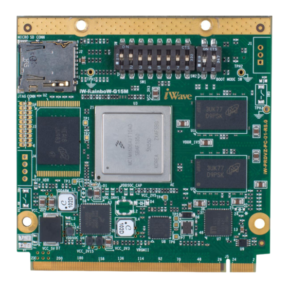
Qseven PMIC SOM Silk Screen i.MX6 Qseven PMIC SOM’s PCB silkscreen top view and bottom view are shown in the below figures to identify the optional feature’s location on SOM. This will be helpful for mounting the optional features in i.MX6 Qseven PMIC SOM. -
Page 81: Figure 19: Silk Screen Bottom View
Qseven PMIC SOM Hardware User Guide Figure 19: Silk Screen Bottom View REL 1.2 iWave Systems Technologies Pvt. Ltd. Page 81 of 82... -
Page 82: I.mx6 Qseven Pmic Som Development Platform
Systems supports iW-RainboW-G15D – i.MX6 Qseven Development Platform with i.MX6 Qseven PMIC SOM and Generic Qseven Carrier board for complete validation of i.MX6 Qseven PMIC SOM functionality with complete BSP support. For more details on i.MX6 Qseven PMIC SOM Development platform, visit the below web link. http://www.iwavesystems.com/product/development-platform/i-mx6-q7-development-kit-18/i-mx6-q7- development-kit.html...
Need help?
Do you have a question about the i.MX6 Qseven PMIC SOM and is the answer not in the manual?
Questions and answers