Sign In
Upload
Manuals
Brands
Iwave Manuals
Motherboard
iW-RainboW-G15M
User Manuals: Iwave iW-RainboW-G15M SODIMM SOM
Manuals and User Guides for Iwave iW-RainboW-G15M SODIMM SOM. We have
2
Iwave iW-RainboW-G15M SODIMM SOM manuals available for free PDF download: Hardware User's Manual, User Manual
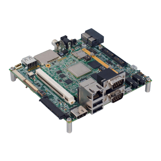
iWave iW-RainboW-G15M Hardware User's Manual (82 pages)
Brand:
iWave
| Category:
Computer Hardware
| Size: 4 MB
Table of Contents
Hardware User Guide
1
Table of Contents
4
1 Introduction
7
Purpose
7
Qseven SOM Overview
7
List of Acronyms
7
Table 1: Acronyms & Abbreviations
7
Terminlogy Description
9
References
9
Table 2: Terminology
9
Important Note
10
2 Architecture and Design
11
I.mx6 Qseven PMIC SOM Block Diagram
11
Figure 1: I.mx6 Qseven SOM Block Diagram
11
I.mx6 Qseven PMIC SOM Features
12
I.mx6 CPU
14
Figure 2: I.mx6Q Simplified Block Diagram
14
Pmic
15
Boot Switches
15
Figure 3: Boot Switches
15
Boot Mode Switch
16
Table 3: Boot Mode Settings Truth Table
16
Boot Media Setting Switch
17
Memory
18
Ddr3 Sdram
18
SPI nor Flash
18
Emmc Flash
18
Micro SD Slot
18
Figure 4: Micro SD Slot
18
Qseven PCB Edge Connector
19
Figure 5: Qseven PCB Edge Connector
19
Data UART Interface (UART5)
20
Gigabit Ethernet Interface
20
Pcie Interface
20
SATA Interface
21
Table 4: Compatible Magnetics
21
USB 2.0 Host Interface
21
AC'97/I2S Audio Interface
22
SD/MMC Interface
22
USB 2.0 OTG Interface
22
HDMI Interface
23
LVDS Display Interface
23
CAN Interface
24
LPC/GPIO Interface
24
SPI Interface
24
Power Control Signals
25
Power Input
25
Power Management Signals
25
I2C Interface
26
Manufacturing/Debug UART Interface (UART2)
26
PWM Interface
26
WDOG Interface
26
Table 5: 230-Pin PCB Edge Connector Pin Assignment
27
Expansion Connector1 Interfaces
42
Figure 6: Expansion Connector1
42
MIPI DSI Interface
43
Parallel Camera Interface1
43
Parallel LCD Display Interface
43
Data UART Interface (UART1 & UART3)
44
ESAI Interface
44
SPDIF Interface
44
Table 6: Expansion Connector1 Pin Assignment
45
Expansion Connector2 Interfaces
51
Figure 7: Expansion Connector1
51
MIPI CSI Interface
52
Parallel Camera Interface2
52
Data UART Interface (UART4)
53
Keypad Interface
53
Memory Bus Interface
53
MLB Interface
53
Table 7: Expansion Connector2 Pin Assignment
54
Optional Features
60
NAND Flash
60
RTC Controller
60
PMIC OTP Header
61
Figure 8: PMIC OTP Header
61
Table 8: PMIC OTP Header Pin Assignment
61
JTAG Header
62
Figure 9: JTAG Header
62
Table 9: JTAG Header Pin Assignment
62
Table 10: JTAG Header - BOM
63
Debug UART Header
64
Figure 10: Debug UART Header
64
Table 11: Debug UART Header Pin Assignment
64
Table 12: Debug UART Header - BOM
64
Power in Connector
65
Figure 11: 2Pin Power Connector
65
Table 13: 2Pin Power Connector
65
Table 14: Power in Connector - BOM
65
3 Technical Specification
66
Electrical Characteristics
66
Power Input Requirement
66
Table 15: Power Input Requirement
66
Power Input Sequencing
67
Figure 12: Qseven SOM Power Sequence
67
Table 16: Power Sequence Timing
67
Power Consumption
68
Table 17: Power Consumption¹
68
Environmental Characteristics
69
Environmental Specification
69
Heat Spreader
69
Table 18: Environmental Specification
69
Rohs Compliance
70
Electrostatic Discharge
70
Figure 13: Heat Spreader Dimensions
70
Mechanical Characteristics
71
Qseven SOM Mechanical Dimensions
71
Figure 14: Mechanical Dimension of Qseven SOM- Top View
71
Figure 15: Mechanical Dimension of Qseven SOM- Bottom View
72
Figure 16: Mechanical Dimension of Qseven SOM- Side View
72
Guidelines to Insert the Qseven SOM into Carrier Board
73
Figure 17: Qseven Module Insertion Procedure
73
4 Ordering Information
74
Table 19: Orderable Product Part Numbers
74
5 Migration Information
78
Table 20: Differences between I.mx6 Qseven Non PMIC SOM and I.mx6 Qseven PMIC SOM
78
I.mx6 Qseven PMIC SOM Silk Screen
80
Figure 18: Silk Screen Top View
80
6 Appendix I
80
Figure 19: Silk Screen Bottom View
81
I.mx6 Qseven PMIC SOM Development Platform
82
Figure 20: I.mx6 Qseven PMIC SOM Development Platform
82
7 Appendix II
82
Advertisement
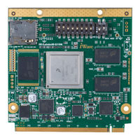
Iwave iW-RainboW-G15M User Manual (59 pages)
Brand:
Iwave
| Category:
Motherboard
| Size: 2 MB
Table of Contents
Table of Contents
4
1 Introduction
8
Purpose
8
Scope
8
List of Acronyms
8
2 Board Support Package
10
Bsp Driver Details
10
Bsp Supported Features
10
Driver Source Description
10
Device Tree Source Description
12
Bsp Compilation
14
Host Requirements
14
Setting up Build Environment
14
Android Build Procedure
15
Bsp Standalone Compilation
17
U-Boot
17
Kernel
18
Bsp Miscellaneous Settings and Configurations
19
I2C Device on the Kernel Image
19
Uart
19
Default Linux Boot Logo
19
Display Device on the Linux Image
20
Modify Display Density
20
3 Binary Programming
21
Mfg -Tool Programming
21
Requirements
21
Mfg-Tool
21
Figure 1: Boot Device Memory Layout
21
Programming Device Selection
22
Programming the Binaries
24
Limitations
25
Figure 2: Platform Detection
25
Figure 3: Binary Programming Succeed
25
Manual Sd Card Programming
27
Requirements
27
Sd Card Partition
27
Binary Programming
28
4 Android
29
Boot-Up
29
Figure 4: Android Desktop
29
Figure 5: Launcher Pad
29
Browser
30
Figure 6: Android Application Screen1
30
Figure 7: Browser
30
Gallery
31
Figure 8: Browser Terms and Conditions
31
Figure 9: Browser Set Clock and Time
31
Figure 10: Gallery
32
Figure 11: Gallery with Multimedia Files
32
Figure 12: Gallery with Images
32
Camera
33
Figure 13: Camera Application Icon
33
Figure 14: Camera Window
33
Figure 15: Camera Options Icon
34
Figure 16: Switch Camera Mode
34
Figure 17: Switch Camera Icon
35
Audio in Test
36
Figure 18: Sound Recorder
36
Figure 19: Sound Recording Window - Start
36
Figure 20: Sound Recording Window - Stop
36
Audio out Test
37
Figure 21: Playing the Recorded Audio
37
Figure 22: Music
37
Clock Settings
38
Figure 23: Settings Menu
38
Figure 24: Clock
38
Usb Otg Device Test
39
Figure 25: Alarm Settings
39
Figure 26: Usb Otg Device - Target Board
39
Figure 27: Usb Otg Device - Host Pc
40
Figure 28: Usb Otg Device Connection Option
40
Figure 29: Mounted Internal Storage Device
41
Usb Host - Hid Class
42
Key Board Test
42
Mouse Test
42
Figure 30: Keyboard Test
42
Figure 31: Mouse Pointer
42
Iwave Test Application
43
Uart Interface
43
Figure 32: Iwave Test Application Icon
43
Figure 33: Iwave Test Application
43
Figure 34: Uart Window
44
Figure 35: UART Window-Options
45
Figure 36: UART Window-Select Device
45
Can Interface
46
Figure 37: UART Window-Change Baud Rate
46
Figure 38: CAN Window-1
46
Light Sensor
47
Figure 39: CAN Window-2
47
Figure 40: Light Sensor
47
Pressure Sensor
48
Temperature Sensor
48
Figure 41: Pressure Sensor
48
Figure 42: Temperature Sensor
48
Accelerometer Sensor
49
Magnetometer Sensor
49
Figure 43: Accelerometer Sensor
49
Hdmi Test
50
5 Command Line Test
51
Block Devices Test (Sd/Emmc/Usb Host/Sata Test)
51
Lcd Back Light Testing
51
Lvds Back Light Testing - Optional
51
Pcie Device Test
52
6 Boot Arguments
53
Micro Sd Boot
53
Standard Sd Boot
53
Emmc Boot
53
Sata Boot
54
Lcd Settings
54
Hdmi Settings
54
Dual Disaplay
55
Optional Features Settings
56
Permanent Mac Address
56
7 Appendix
57
Frequently Asked Question
57
Advertisement
Related Products
iWave iW-RainboW-G15S
iWave iW-RainboW-G21D
iWave iW-RainboW-G15D
iWave iW-RainboW-G25D
iWave iW-RainboW-G27M
iWave iW-RainboW-G20M
iWave iW-RainboW-G18D
iWave iW-RainboW-G20D
iWave iW-RainboW-G22D
iWave iW-RainboW-G27D
Iwave Categories
Motherboard
Computer Hardware
Single board computers
Control Unit
Microcontrollers
More Iwave Manuals
Login
Sign In
OR
Sign in with Facebook
Sign in with Google
Upload manual
Upload from disk
Upload from URL