
Related Manuals for iWave i.MX53


Summary of Contents for iWave i.MX53
- Page 1 MXM CPU Module Hardware User Guide i.MX53 MXM CPU Module Hardware User Guide Rev 1.2 iWave Systems Technologies Pvt. Ltd. Page 1 of 33...
- Page 2 If you are not the intended recipient (or authorized to receive for the recipient), you are hereby notified that any disclosure, copying distribution or use of any of the information contained within this document is STRICTLY PROHIBITED. Thank you. “iWave Systems Tech. Pvt. Ltd.” Rev 1.2 iWave Systems Technologies Pvt.
-
Page 3: Table Of Contents
MXM CPU Module Hardware User Guide Table of Contents INTRODUCTION ......................5 ........................5 VERVIEW ....................5 EFERENCE OCUMENTS ........................6 ERMINOLOGY ....................... 7 LOCK IAGRAM ........................8 EATURES .MX53 CPU M ...................... 9 ODULE .MX53 CPU M ................. 10... - Page 4 MXM CPU Module Hardware User Guide List of Figures Figure 1: Block Diagram of i.MX53 CPU Module ................. 7 Figure 2: i.MX53 CPU Module ...................... 9 Figure 3: Power ON sequence....................28 Figure 4: Mechanical Drawing of i.MX53 CPU Module .............. 31 List of Tables Table 1: Terminology ........................
-
Page 5: Introduction
The i.MX53 CPU Module is ideal for applications that require advanced user interfaces, sophisticated video processing, 2D and 3D graphics, single or dual high resolution displays, and a high level of system integration. -
Page 6: Terminology
MXM CPU Module Hardware User Guide Terminology The following is a list of commonly occurring acronyms and abbreviations used throughout this document. Table 1: Terminology Term Definition Controller Area Network CMOS Complementary Metal-Oxide Semiconductor Central Processing Unit CSPI Configurable Serial Peripheral Interface... -
Page 7: Block Diagram
ULPI Ultra Low pin Interface Universal Serial Bus Block Diagram The high level block diagram of i.MX53 CPU Module(SOM) is shown in Figure 1. Figure 1: Block Diagram of i.MX53 CPU Module Rev 1.2 iWave Systems Technologies Pvt. Ltd. Page 7 of 33... -
Page 8: Features
MXM CPU Module Hardware User Guide Features The i.MX53 CPU Module supports the following features: Standard Features Processor: Freescale i.MX536 @ 800MHz 512MB DDR2 SDRAM (Expandable up to 2Gbyte) 16MB SPI NOR Flash Micro SD Slot Debug UART Console... -
Page 9: I.mx53 Cpu Module
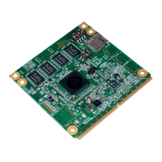
MXM CPU Module Hardware User Guide Functional Description i.MX53 CPU Module Top view of i.MX53 CPU Module is shown in Figure 2. Figure 2: i.MX53 CPU Module Rev 1.2 iWave Systems Technologies Pvt. Ltd. Page 9 of 33... -
Page 10: I.mx53 Cpu Module Description
Note2: It is recommended not to use any external pull down/ pull up for the boot configurations signals available at edge or expansion connector since these signals are used for boot device selection when processor POR_B is de-asserted. Please refer i.MX53 user Manual Chapter “System Boot” section “Device Configuration” for boot configuration signals. -
Page 11: Uart Connector (J3)
MXM CPU Module Hardware User Guide 1.7.2 UART Connector (J3) Processor UART1 RXD, TXD signals are brought to a 3-pin 80-mil connector through a RS232 transceiver for debug console. This UART connector is optional & by default for debug this UART is not used. -
Page 12: External Interface
2. External Interface On-board connectors link the i.MX53 CPU Module to external interfaces such as SD,UART etc. Refer Figure 2 for the location of the connectors on i.MX53 CPU Module. The Table 4 lists the function of each of the board’s connectors. -
Page 13: Jtag Header [J4]
MXM CPU Module Hardware User Guide JTAG Header [J4] An 20-pin customized connector is used to debug the processor and to program the flash with Host debugger software. Table 7: JTAG Header[J4] Pin Assignments Pin No. Signal name IO Level Pin No. - Page 14 MXM CPU Module Hardware User Guide E1-10 2.5V Output gpio6_GPI[28] Ball: AB13 LVDS1_TX1_P 2.5V Output gpio6_GPI[29] Ball: AC13 E3-1 LVDS1_TX1_N E3-2 2.5V Output gpio6_GPI[30] Ball: AB14 E3-3 LVDS1_TX0_P 2.5V Output gpio6_GPI[31] Ball: AC14 E3-4 LVDS1_TX0_N E3-5 2.5V Output gpio6_GPI[26]...
- Page 15 MXM CPU Module Hardware User Guide TVDAC_IOR 2.8V TVDAC_IOR Ball:AC21 TVDAC_IOG 2.8V TVDAC_IOG Ball:AB20 TVDAC_IOB 2.8V TVDAC_IOB Ball:AC19 NANDF_CS0 3.3V GPIO gpio6_GPIO[11 Ball: W12 LVDS0_CLK_P 2.5V Output gpio7_GPI[24] Ball: AC16 LVDS0_CLK_N 2.5V Output gpio7_GPI[25] Ball: AB16 LVDS0_TX0_P 2.5V Output...
- Page 16 MXM CPU Module Hardware User Guide CSI0_DAT17 3.3V gpio6_GPIO[3] Ball: T5 CSI0_DAT18 3.3V gpio6_GPIO[4] Ball: U3 CSI0_DAT19 3.3V gpio6_GPIO[5] Ball: U4 CSI0_DAT15 3.3V gpio6_GPIO[1] Ball: U2 CSI0_DAT14 3.3V gpio6_GPIO[0] Ball: U1 CSI0_DAT4 3.3V gpio5_GPIO[22] Ball: R1 CSI0_DAT11 3.3V gpio5_GPIO[29]...
- Page 17 MXM CPU Module Hardware User Guide GPIO_16* 3.3V gpio7_GPIO[11] Not Connected Ball: C6) Muxed with Pin GPIO_4/DISP0_DAT22* 3.3V/ gpio5_GPIO[16] By default 2.8V DISP0_DAT22 is connected GPIO_3/DISP0_DAT20* 3.3V/ gpio5_GPIO[14] By default 2.8V DISP0_DAT20 is connected KEY_COL0 3.3V gpio4_GPIO[6] Ball: C5 KEY_COL1 3.3V...
- Page 18 MXM CPU Module Hardware User Guide DISP0_DAT4 2.8V gpio4_GPIO[25] Ball: G2 DISP0_DAT0 2.8V gpio4_GPIO[21] Ball: J5 DISP0_DAT11 2.8V gpio5_GPIO[5] Ball: H5 DISP0_DAT9 2.8V gpio4_GPIO[30] Ball: E2 DISP0_DAT10 2.8V gpio4_GPIO[31] Ball: G3 DISP0_DAT7 2.8V gpio4_GPIO[28] Ball: H6 EIM_OE* 3.3V emi_EIM_OE...
- Page 19 MXM CPU Module Hardware User Guide connected. Ball:W8 Connected to on module SPI Flash WP pin POWER_ON Input Connected to ON pin of PMIC. Can be used to connect a pushbutton to power on the SOM module RST_IN# (Optional) 3.3V...
-
Page 20: Table 9: Pcb Edge Bottom Side [J8] Pin Assignments
MXM CPU Module Hardware User Guide Board Edge Connector (PCB Edge BOTTOM Side) Table 9: PCB Edge BOTTOM Side [J8] Pin Assignments Direction Out of Reset Description Level w.r.t Condition-Block Signal Name VCC (5V) E2-1 E2-2 VCC (5V) Main Input to the... - Page 21 MXM CPU Module Hardware User Guide EIM_DA4 3.3V emi_NAND_EIM Ball:AB6 _DA[4] EIM_DA5 3.3V emi_NAND_EIM Ball:V9 _DA[5] EIM_DA6 3.3V emi_NAND_EIM Ball:Y9 _DA[6] EIM_DA7 3.3V emi_NAND_EIM Ball:AC5 _DA[7] EIM_DA8 3.3V emi_NAND_EIM Ball:AA8 _DA[8] PATA_DIOW * 3.3V gpio6_GPIO[17] Optionally used ad UART1...
- Page 22 MXM CPU Module Hardware User Guide KEY_ROW3/I2C0 Data 3.3V gpio4_GPIO[13] I2C0 Data Signal (Ball: D4) Connected to PMIC with address 0x69|R/W KEY_COL3/ I2C0 clock * 3.3V gpio4_GPIO[12] I2C0 clock Signal(Ball: F6) Shared with pin162 Connected to PMIC with address...
- Page 23 MXM CPU Module Hardware User Guide _DA[12] SD1_CLK 3.3V gpio1_GPIO[20] Ball: E16 EIM_EB0 3.3V emi_EIM_EB[0] Ball: AC3 PATA_DATA12 3.3V gpio2_GPIO[12] Ball: N5 PATA_DATA14 3.3V gpio2_GPIO[14] Ball: P6 EIM_DA13 3.3V emi_NAND_EIM Ball: AC7 _DA[13] EIM_DA15 3.3V emi_NAND_EIM Ball: AA9 _DA[15] PATA_DATA15 3.3V...
- Page 24 MXM CPU Module Hardware User Guide EIM_D21 3.3V gpio3_GPIO[21] Ball: V3 EIM_D28 3.3V gpio3_GPIO[28] Ball: AA1 EIM_EB2 3.3V gpio2_GPIO[30] Ball: Y3 EIM_D17 3.3V gpio3_GPIO[17] Ball: U5 Used as eCSPI1_MISO EIM_D18 3.3V gpio3_GPIO[18] Ball: V1 Used as eCSPI1_MOSI EIM_D16 3.3V...
- Page 25 MXM CPU Module Hardware User Guide (Ball: A5) Shared with Pin173 EIM_D19* 3.3V gpio3_GPIO[19] Default not connected Connected to SPI flash Chip select Ball:V2 LED1 3.3V Output Link activity LED Indication. This pin is driven active when a valid link is...
-
Page 26: On Module Io Muxing
Used for power on sequencing of carrier board Note2: For IO Muxing please refer the FSL i.MX53 IO Mux sheet Note3: For Default pin configuration status also refer i.MX53 datasheet. On Module IO Muxing Below table gives the details on the signals used by on module components/connectors. - Page 27 MXM CPU Module Hardware User Guide SPI Flash write GPIO_WPn EIM_CS0 Output gpio2_GPIO[23] ALT1 protect Signal eMMC eSDHC3 Reset for eSDHC3_RST PATA_DA_0 Output ALT2 eMMC eSDHC3_CLK PATA_IORDY Output ALT2 eSDHC3 Clock Signal eSDHC3_CMD PATA_RESET_B ALT2 eSDHC3 CMD Signal eSDHC3_DAT0...
-
Page 28: Power On Sequence
MXM CPU Module Hardware User Guide Power ON sequence All peripheral power supplies should be powered On only after the CPU Module is powered On completely. ie after the PWR_RDY goes high. This is to ensure that there is no back voltage (leakage) from any supply on the board towards the 3.3 V supply IO lines (for example, from the parts that use both 1.8 V and... -
Page 29: Mating Connector Details
MXM CPU Module Hardware User Guide Mating Connector Details Edge Connector (J8) The following connector can be used as a mating connector for the edge connector on the carrier card. Table 11: Mating connector for Edge Connector (J8) Manufacturer... -
Page 30: Leds Description
MXM CPU Module Hardware User Guide LEDs Description LEDs Description Once the module is turned ON, the LEDs on the module can be observed for the power good status. Table 12: LEDs Description Sl. No. Color Function GREEN Power Good LED Note: If the LED is blinking, this indicate power on sequence is not proper Rev 1.2... -
Page 31: Mechanical Drawing
Mechanical Drawing I.MX53 CPU Module The mechanical drawing of the i.MX53 CPU Module is shown in Figure 4. Figure 4: Mechanical Drawing of i.MX53 CPU Module Note: Max Height of components in TOP is 4mm & BOTTOM is 3mm (Excluding the optional connectors) Please contact iWave for 3D &... -
Page 32: Ordering Information
MXM CPU Module Hardware User Guide Ordering Information Table 13: Ordering Information Part Number Temp. Range Specification iW-G11M1-MXXC 0C to +70C i.MX536 512MB DDR2 16MB SPI NOR Micro SD connector XX- No OS /OS is customer specific iW-G11M2-MXXA -40C to +85C i.MX536... -
Page 33: Technical Support
MXM CPU Module Hardware User Guide 7. Technical Support iWave Systems Technologies Pvt. Ltd. # 7/B, 29th Main, BTM Layout 2nd Stage, Ban galore - 560 076 Phone : +91-80-26683700, 26786245 : +91-80-26685200 Email :mktg@iwavesystems.com : www.iwavesystems.com Rev 1.2 iWave Systems Technologies Pvt.
Need help?
Do you have a question about the i.MX53 and is the answer not in the manual?
Questions and answers