RTS KP-32 User Instructions
Hide thumbs
Also See for KP-32:
- User manual (34 pages) ,
- Installation manual (2 pages) ,
- User instructions (106 pages)

Related Manuals for RTS KP-32


Summary of Contents for RTS KP-32
- Page 1 NSTRUCTIONS KP-32 K EYPANEL 2.1.0 P TO AND NCLUDING ERSION EKP-32 E XPANSION ANEL LCP-32 L EVEL ONTROL ANEL Rev. 16 DECEMBER/2011 F.01U.193.253...
- Page 2 KP-32 User Manual ROPRIETARY OTICE The product information and design disclosed herein were origi- nated by and are the property of Bosch Security Systems, Inc. Bosch reserves all patent, proprietary design, manufacturing, repro- duction, use and sales rights thereto, and to any article disclosed therein, except to the extent rights are expressly granted to others.
-
Page 3: Important Safety Instructions
KP-32 User Manual Important Safety Instructions Read these instructions. Keep these instructions. Heed all warnings. Follow all instructions. Do not use this apparatus near water. Clean only with dry cloth. Do not block any ventilation openings. Install in accordance with the manufacturer’s instructions. - Page 4 KP-32 User Manual Bosch Security Systems, Inc. Rev. 16 F.01U.193.253 User Manual...
-
Page 5: Table Of Contents
Table Contents Important Safety Instructions ..........................iii INTRODUCTION ......................... 3 Description ...............................3 Features ..............................3 Options ..............................4 Connector Module ............................... 4 CSI-100 Coaxial System Interface Module ......................5 EKP-32 Expansion Keypanel ..........................5 LCP-32/16 Level Control Panels ......................... 6 INSTALLATION .......................... 7 Rack Mount Considerations ........................7 Option DIP Switch Settings ........................8 Switch 1: Latch Enable/Disable .......................... - Page 6 Storing an Autodial Number in the TIF-951 ..................... 23 Storing an Autodial Number in the KP-32 ......................23 Dialing an Autodial Number ..........................23 Dialing And Hanging Up Using The KP-32 Dialing Menu ..............24 Manual Dialing ..............................24 Redial ................................. 24 Autodial ..............................25...
- Page 7 Method 1: Clearing the Call Waiting Window and Copying it to a Key ............33 Method 2: Copying a Blank Key Assignment to the key you want to Clear ..........33 KP-32 MENU SYSTEM ......................35 Menu System, Menu Access ........................35 Menu System, Display Menu .........................36 Display Menu, Asgn Type ..........................
- Page 8 KP-32 User Manual Key Assign Menu, Key Gain ..........................40 Key Assign Menu, Reset Vols .......................... 41 Key Assign Menu, Setup Page .......................... 41 Key Option Menu ..........................42 Key Option Menu, Auto Dial ..........................42 Key Option Menu, Chime ..........................42 Removing the chime option from a key ......................
- Page 9 KP9X Autodial Sequences ..........................65 Storing an Autodial Number in the TIF ......................65 Dialing an Autodial Number Stored in the TIF ..................... 66 KP-32 MENU SYSTEM QUICK REFERENCE ..............67 Menu Access ............................67 Menu List ...............................67 MODE 2 OPERATION ......................69 Section 2 ..............................69...
- Page 10 Installation of the RVON-1 Card ......................81 RVON-1 Relay ..............................82 Addresses and the RVON-1 ........................83 Configure the RVON-1 from the KP-32 ....................84 Top Level Menu, Service, RVON Setup ......................84 Set the IP Address from the Service Level Menu .......................84 Top Level Menu, RVON Conn.
- Page 11 KP-32 User Manual Download RVON-1 Firmware Through AZedit ...................89 Basic Network Configuration ........................91 LAN vs. WAN ..............................91 Local Area Network ............................91 Wide Area Network ............................92 Accessing The Wide Area Network (WAN) ..................... 93 Network Address Translation (NAT) ........................ 93 Ports ...................................
- Page 12 KP-32 User Manual User Manual F.01U.193.253 Bosch Security Systems, Inc. Rev. 16...
- Page 13 Setup page usage for the KP-32 and EKP-32 ..............28 FIGURE 9. LCP-32 correspondence to KP-32 and EKP-32 ............... 49 FIGURE 10. Flash Chip placement on the KP-32 motherboard ............80 FIGURE 11. Local Area Network Diagram ................... 92 FIGURE 12. Wide Area Network Diagram ................... 92 FIGURE 13.
- Page 14 KP-32 User Manual F.01U.193.253 User Manual Rev. 16 Bosch Security Systems, Inc.
-
Page 15: Introduction
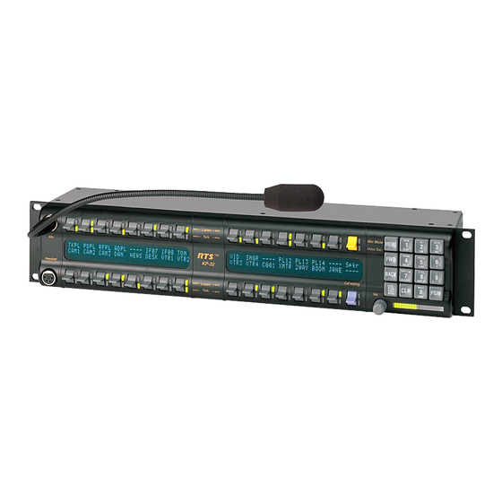
Description The RTS Model KP-32 Keypanel fits in a standard 19" rack and is two (2) rack spaces high. It has 32 lever keys: 30 keys are for intercom talk/listen assignment; one (1) key is for call waiting response; and one (1) key is for headset/microphone/ program selection and volume setup. -
Page 16: Options
4 Introduction KP-32 User Manual KP-32 Keypanel Front View. FIGURE 14. Options Connector Module KP-32 GPI Connector Module FIGURE 15. Provides connectors for two (2) line-level audio inputs (program 1 and 2), an unswitched, balanced microphone preamplifier output, an external headset, an external speaker output, and a foot switch input (for remote switch activation of all armed talk keys, or just one [1] key). -
Page 17: Csi-100 Coaxial System Interface Module
KP-32 User Manual Introduction 5 CSI-100 Coaxial System Interface Module KP-32 CSI-100 coaxial system interface board FIGURE 16. Provides the ability to link the unit to the matrix using a single 75 coaxial cable. The interface converts all audio and data streams to a single transmission path. -
Page 18: Lcp-32/16 Level Control Panels
6 Introduction KP-32 User Manual LCP-32/16 Level Control Panels LCP-32/16 level control panel front view FIGURE 18. Provides easy adjustment of point-to-point and party line listen levels for individual intercom keys. One (1) LCP-32/16 adjusts one (1) row of keys. -
Page 19: Installation
CHAPTER 2 Installation Rack Mount Considerations Elevated Operating Ambient - If installed in a closed or multi-unit rack assembly, the operating ambient temperature of the rack environment may be greater than room ambient. Therefore, consideration should be given to installing the equipment in an environment compatible with the Tma (Maximum Ambient Temperature) specified by the manufacturer. -
Page 20: Option Dip Switch Settings
Default setting = Open: enable With Screen Saver enabled, the KP-32 shuts off the display and enter a low power state after a few minutes of inactivity. The display reactivates instantaneously on an incoming call or when the keypanel operator actuates any control. As with all fluorescent and back-lit LCD displays, some dimming occurs after many years of operation. -
Page 21: Switch 5: Footswitch Enable / Disable
KP-32 User Manual Installation 9 Switch 5: Footswitch Enable / Disable* Default = Open: disabled Description: The optional Connector Module has a footswitch (GRP CALL) input. If the footswitch is enabled (DIP switch 5 set to the closed position), the keys latched on do not activate until the footswitch is closed. Latched keys are indicated by a winking green talk LEDs (on time less than off time), and when the footswitch is activated, the LEDs provide the normal ... -
Page 22: Address Switch Setting
Intercom port connectors on the Zeus back panel are arranged in three (3) groups of eight (8) intercom ports. For each group, intercom port connectors are labeled ID 1, ID 2, etc. When you connect a KP-32 keypanel to Zeus, set the Address switch to match the corresponding ID number on the Zeus back panel. - Page 23 Address Number vs. Intercom Port Numbers for 8-Port Audio I/O Cards (ADAM and ADAM CS Intercom Systems) TABLE 1. Address Card Numbers (bold headings) and Port Numbers Cards 1-25 Cards 25-50 Cards 51-75...
-
Page 24: Adam Cs With 50-Pin Telco Back Panel
ADAM CS with 50-pin Telco back panel: Determine the address setting from Table 1. To use the table, locate the intercom port number to which the KP-32 is connected. Then, read across to the Address column to find the Address number. Set the KP-32 Address switch to this number. -
Page 25: Connections
KP-32 and on an optional EKP-32 Expansion Panel. An interconnect cable is supplied with each LCP-32. Connect the first LCP-32 to the LCP connector on the KP-32. Connect the second LCP-32 to the first LCP-32, and so forth. -
Page 26: Power Supply Connector
14 Installation KP-32 User Manual Power Supply Connector Align and insert the external power supply connector. Tighten the locking ring. Connect a power cord to the power supply and to an AC power source. The power supply accepts 100-240 VAC, 50/60Hz. -
Page 27: Basic Operation
Screen Saver Operation If the KP-32 is set for screen saver operation, the alphanumeric display automatically shuts off after several minutes of inactivity. The display reactivates on incoming call or when the keypanel operator actuates any control. DIP switch 3 enables/ disables screen saver operation. -
Page 28: Intercom Keys And Displays
16 Basic Operation KP-32 User Manual Intercom Keys and Displays Alphanumeric Display Indications for Intercom Keys Upper Case Letters: Upper case letters indicate keys that have any kind of talk assignment, with or without a corresponding listen assignment. Example: DIR1 Lower Case Letters: Lower case letters indicate keys that have only a listen assignment. -
Page 29: Flashing Red Talk Led & Flashing Display Alternating Pattern Of Alpha & (-**-) (Busy)
NOTE: Latching may be turned off for the entire keypanel by setting DIP switch 1 on the KP-32 back panel to the Closed position. Latching may be disabled for individual keys on a keypanel using AZedit: Click the KP button on the AZedit toolbar to open the Keypanels / Ports setup screen. -
Page 30: Operation Of Intercom Keys With Auto Functions
18 Basic Operation KP-32 User Manual Operation of Intercom Keys with Auto Functions NOTE: Assignment of keys with auto functions is described in the programming sections that follow. Descriptions of the auto functions are also contained in the Glossary. Operation of keys with auto functions is as follows: Talk + auto follow Talk and listen can be activated separately. -
Page 31: Operation Of Intercom Talk Keys With The Speaker Dim Setting
If an intercom key is assigned to talk to an intercom port that is designated as a TIF port in AZedit, placing the key in the talk position activates the KP-32 dialing menu. See “Telephone Operation” on page 21, for further information. - Page 32 20 Basic Operation KP-32 User Manual User Manual Bosch Security Systems, Inc. F.01U.193.253 Rev. 16...
-
Page 33: Telephone Operation
TIF assignment. We recommend a talk+auto listen assignment. Receiving A Phone Call When there is an incoming telephone call, the talk LED flashes red next to the KP-32 key that is assigned to the TIF. Activate the key to answer the call. -
Page 34: Kp9X Manual Dial Sequence
On the keypad, tap CLR PHONE PGM. Activate the TIF talk key. The talk LED turns green, the on LED at the TIF activates, and you should hear dial tone at the KP-32. Dial the telephone number. Digits scroll in the display above the TIF key. When the far end answers, you can dial additional digits (to access a mail system or automated response system, etc.). -
Page 35: Storing An Autodial Number In The Tif-951
After storing the autodial number, hang up using the KP9X hang-up sequence. Storing an Autodial Number in the KP-32 To store an autodial number in the KP-32, do the following: Press Menu. Display appears in the call waiting window. -
Page 36: Dialing And Hanging Up Using The Kp-32 Dialing Menu
24 Telephone Operation KP-32 User Manual Dialing And Hanging Up Using The KP-32 Dialing Menu The dialing menu only activates when talking to an intercom port that has the Port is TIF check box activated in AZedit. (In AZedit, click the KP button to access the Keypanels/Ports screen, then select the port where the TIF is connected, then click the Edit button, then click the Advanced tab. -
Page 37: Autodial
KP-32 User Manual Telephone Operation 25 Autodial NOTE: Autodial is only available after you have saved autodial numbers. Turn ON the TIF talk key. Manual Dial displays in the Call waiting window. Tap the or key until Auto Dial displays.... - Page 38 26 Telephone Operation KP-32 User Manual User Manual Bosch Security Systems, Inc. F.01U.193.253 Rev. 16...
-
Page 39: Kp9X Series Keypad Programming
CHAPTER 5 KP9X Series Keypad Programming NOTE: A summary of the keypad programming sequences is located at the back of the manual for quick reference. Keypad Programming, Display Requests Display requests let you view information about the keypanel configuration. You can display information by two methods: either by entering sequences on the programming keypad, or by scrolling the names of display requests in the Call waiting window and then selecting the desired display request. -
Page 40: Display Setup Page Assignments
“Main” setup page. Additional setup pages are assigned to any connected expansion panels, and are referred to as Expansion 1, Expansion 2, etc.). Since the KP-32 requires 2 setup pages, it uses the main page assignments and also one expansion page (). -
Page 41: Display Requests Using Scrolling
Turns on tone generator. CLR to quit and turn off tone generator. Epnl PGM: Displays setup page assignments. Mn=KP-32 bottom row keys, X1=KP-32 top row keys, X2=EKP-32 bottom row keys, X3=EKP-32 top row keys. Gain PGM: After selecting this item, tap up on any listen key with a point-to-point or party line assignment. The current listen gain from this keypanel to the intercom port or party line displays in the Call waiting window. -
Page 42: Keypad Programming, Assigning Setup Pages
30 KP9X Series Keypad Programming KP-32 User Manual Keypad Programming, Assigning Setup Pages Tap the E-PNL key. Select one of the four setup pages: tap 1, or 2, etc. Tap the PGM key. Tap any key in the row of keys where you want to assign the setup page. -
Page 43: Programming Key Assignments Using Copy
KP-32 User Manual KP9X Series Keypad Programming 31 FUNC RELAY Relay or GPI output. Auto function assignment only: Tap an additional number to select the desired auto function: Auto listen (listen keys only) Auto follow (listen keys only) All call (talk level 1 only) -
Page 44: Programming Key Assignments Using Alpha Scrolling
32 KP9X Series Keypad Programming KP-32 User Manual Press the talk or listen key from which you wish to copy. Press the talk or listen key to which you wish to copy. The name of the key assignment should appear in the display above the key. -
Page 45: Clearing A Key Assignment
KP-32 User Manual KP9X Series Keypad Programming 33 Clearing a Key Assignment There are two ways to clear a key assignment: Method 1: Clearing the Call Waiting Window and Copying it to a Key Clear the Call waiting window, if necessary. Tap up one or more times on the call waiting key. - Page 46 34 KP9X Series Keypad Programming KP-32 User Manual User Manual Bosch Security Systems, Inc. F.01U.193.253 Rev. 16...
-
Page 47: Menu System
CHAPTER 6 KP-32 M YSTEM NOTE: A chart of the menu system is located at the back of the manual for quick reference. Menu System, Menu Access Clear all names from the call waiting display (if not clear) by tapping UP one or more times on the call waiting key. -
Page 48: Menu System, Display Menu
36 KP-32 Menu System KP-32 User Manual Menu System, Display Menu Use this menu to display information about the keypanel configuration. Display Menu, Asgn Type Displays the talk level 1 assignment types for all keys. Abbreviations for the key assignment types appear in the alphanumeric displays as follows: P-P: Point-to-point talk key. -
Page 49: Display Menu, Panel Id
Display Menu, Version Displays the firmware version of the keypanel. NOTE: For firmware upgrades, contact your intercom system dealer. The KP-32 firmware can be upgraded from AZedit. For more information, see the AZedit user manual. Menu System, Key Assign Menu Use this menu to assign intercom keys, to adjust listen levels for point-to-point keys and party line keys, and to assign setup pages. - Page 50 38 KP-32 Menu System KP-32 User Manual UPL Resrc: Assign a key to activate a UPL resource. IFSL: Assign a key to activate a IFB special list resource. Auto Func: Assign an auto function to a key. (If you select this item, skip the rest of this procedure and go to “Key Assign Menu, Auto Func”...
-
Page 51: Key Assign Menu, Matrix
KP-32 User Manual KP-32 Menu System 39 Key Assign Menu, Matrix Matrix appears only for trunked intercom systems. You must select a remote intercom matrix before assigning intercom keys to destinations in that matrix. You do not need to select matrix to assign keys to destinations in your own matrix. You also do not need to select a matrix when assigning an auto function to a key. -
Page 52: Key Assign Menu, Ifsl
40 KP-32 Menu System KP-32 User Manual Key Assign Menu, IFSL By default, all IFSL resources are restricted and Not Avail displays when you attempt to select this item. To see IFSL resources you must check the appropriate Scroll Enable check boxes in AZedit. (In AZedit, System|IFB Special Lists. Enter check marks in the appropriate Scroll Enable boxes.) -
Page 53: Key Assign Menu, Reset Vols
Key Assign Menu, Setup Page Use this menu item to change the setup page assignments on the KP-32 or EKP-32. One setup page is used for the top row of keys, and another setup page is used for the bottom row. -
Page 54: Key Option Menu
42 KP-32 Menu System KP-32 User Manual Key Option Menu Key Option Menu, Auto Dial Use this menu item to store auto dial numbers. Select Auto Dial. Tap PGM. Phone#? displays. Tap the number keys. The numbers scroll in the Call waiting window. -
Page 55: Clearing A Key Group
KP-32 User Manual KP-32 Menu System 43 Tap CLR when finished. Activating the master key should now cause it and all slave keys to activate. The LEDs for each key activate according to the current key assignment for that key. -
Page 56: Rvon Conn. Menu
44 KP-32 Menu System KP-32 User Manual RVON Conn. Menu The RVON Conn. menu is used to select an RVON connection to use with the keypanel. NOTE: This menu item only appears when you have the RVON option installed and there are RVON devices available. -
Page 57: Service Menu, Caller Vol
KP-32 User Manual KP-32 Menu System 45 Service Menu, Caller Vol. Caller Vol. allows you to enable or disable adjustments made to the caller volume. Select Caller Vol. → Disable Adj appears. To select Disable Adj or Enable Adj use Tap PGM.... -
Page 58: Service Menu, Dsp Func (Gpi Option Only)
46 KP-32 Menu System KP-32 User Manual Service Menu, DSP Func (GPI Option Only) This item accesses the digital signal processing features. Select DSP Func, then tap PGM. Filtering displays. Press to display any of the following items:... -
Page 59: Metering
KP-32 User Manual KP-32 Menu System 47 Tap PGM. → Gating displays. The arrow indicates that gating is now selected. Tap CLR to exit. Run Service Menu, Save Cfg, to save the change. Metering Metering lets you use the Vol. display as an LED bar graph meter to monitor an audio signal for about 1 minute. -
Page 60: Mixing
48 KP-32 Menu System KP-32 User Manual Mixing Mixing lets you route selected audio signals to the intercom system, to the speaker, or to the left or right headphone when using a headset. By default, the microphone signal is routed to the matrix, and the matrix signal is routed to the speaker and to the left and right headphones. -
Page 61: Service Menu, Lcp-32 (Gpi Option Only)
LCP-32 correspondence to KP-32 and EKP-32 FIGURE 22. For example, you may not want to use LCP-32s with the KP-32 but do want to use them with an EKP-32. In this case, you must turn off LCP usage for keys 1-32 as follows: Select LCP-32, then tap PGM.... -
Page 62: Assigning An Input To Activate A Key Group
50 KP-32 Menu System KP-32 User Manual Assigning an Input to Activate a Key Group Select Local GPIO, then tap PGM. Input displays. Tap PGM. GPI Inp #1 displays. Press or to display a different GPI input. Tap PGM to select a GPI input. -
Page 63: Service Menu, Matrix Out
This menu item allows the user to set the minimum volume level for both the keypanel speaker and the headset speaker(s). This is the minimum volume level available on the volume control located on the front panel of the KP-32. -
Page 64: Service Menu, Mod Assign
The KP-32 and EKP-32 use module ID numbers (Mod ID numbers) to define the address of each key and display module. By default, Mod 1 is always assigned to the right half of the KP-32 and this never changes, since this module has the keypad and is unique. -
Page 65: Service Menu, Preamp Out (Gpi Option Only)
KP-32 User Manual KP-32 Menu System 53 Service Menu, Preamp Out (GPI Option Only) Allows the user to choose how audio is routed to the Preamp Output connector. When Switched is chosen, keypanel audio is routed to the preamp output connector when a talk key is latched. When Hot Mic is chosen, audio is always available at the preamp output connector. -
Page 66: Service Menu, Scr Saver
Service Menu, Tone Gen Tone Generator PGM turns the KP-32 tone generator on or off. You can use the tone generator to check the audio path from the keypanel to the matrix and back. NOTE: The microphone is muted when the tone generator is active. -
Page 67: Specifications
CHAPTER 7 Specifications Microphone Preamplifier Electret Mic Input Level @ 1 kHz: ..........................-42dB, 150 Dynamic Mic Input Level @ 1 kHz:........................-50dBm, 150 Output Level (to matrix): ............................ +8dBu, ± 0.2dBu Max Voltage Gain, Mic to Line: ..........................70dB, ± 2dB Frequency Response: ..........................100Hz to 10kHz, ±... -
Page 68: Intercom Input/Output
19" wide x 2RU x 3.5" (90mm) deep Approvals: UL, CSA, VDE, CE Connectors (Other connector options available) Panel Microphone Connector Type: 3-circuit, 1/4" phone jack w/threaded metal bushing, compatible w/ RTS MCP5/6 Pin-out: Tip: +Audio and DC bias Ring:... -
Page 69: Power Input Connector
KP-32 User Manual Specifications 57 Power Input Connector Type:5-pin locking DIN Pin-out: Pin1: Common Pin2: Common Pin3: +5VDC, 1.50A Max. Pin4: -15VDC, 0.150A Max. Pin5: +15VDC, 0.5A Max. Intercom Connectors: Parallel-wired DE9S and RJ12 Connectors Type:DE9S Pin-out: Pin 1: Data +... -
Page 70: Gpi Module Connectors (Optional)
58 Specifications KP-32 User Manual GPI Module Connectors (Optional) Aux 1 In (Auxiliary program input 1) Type: 3-pin female XLR Pin-out: Pin 1: Ground Pin 2: Input + Pin 3: Input - NOTE: Balanced input, +8dBu nominal Aux 2 In (Auxiliary program input 2) -
Page 71: Relay 3 & 4 Out
KP-32 User Manual Specifications 59 Relay 3 & 4 Out Type: 9-pin male D-Sub Pin-out: Pin 1: NC contact 3 Pin 2: COM contact 3 Pin 3: NO contact 3 Pin 4: NC contact 4 Pin 5: COM contact 4... -
Page 72: Oc 1 & 2 Out (J2)
60 Specifications KP-32 User Manual OC 1 & 2 Out (J2) Type: 9-pin male D-Sub Pin-out: Pin 1: Gnd OC1 Pin 2: Emitter OC1 Pin 3: Collector OC1 Pin 4: Gnd OC2 Pin 5: Emitter OC2 Pin 6: Collector OC2... -
Page 73: Mic In (J7) Unbalanced Panel Microphone Input
KP-32 User Manual Specifications 61 MIC In (J7) Unbalanced Panel Microphone Input Type: 3-pin female XLR Pin-Out: Pin 1: Shield (circuit common) Pin 2: DC bias and Audio Plus (+) Pin 3: NOTE: Input level -42.5dBu nominal. MIC Out (J8) Balanced Microphone Output... - Page 74 62 Specifications KP-32 User Manual User Manual Bosch Security Systems, Inc. F.01U.193.253 Rev. 16...
-
Page 75: Kp9X Keypad Sequence Quick Reference
Turn on tone generator. CLR to end. Epnl PGM: Display setup page assignments. Mn=KP-32 top row keys. X1=KP-32 bottom row key. X2=EKP-32 top row keys. X3=EKP-32 bottom row keys. Port / party line listen gain. Turn on listen key. ↓↓ or −− to change gain. -
Page 76: Kp9X Setup Page Assignment
64 KP9X Keypad Sequence Quick Reference KP-32 User Manual KP9X Setup Page Assignment Tap E-PNL. Select a setup page: tap 1, or 2, etc. Tap PGM. Tap any key in top row to assign page to top row. Tap any key in bottom row to assign page to bottom row. -
Page 77: Kp9X Phone Operation
On the keypad, tap CLR-PHONE-PGM. Activate the TIF talk key (talk LED turns green). The on LED at the TIF activates, and you should hear dial tone at the KP-32. Dial the telephone number. Digits scroll in the display above the TIF talk key. When the far end answers, you can dial additional digits (to access a mail system or automated response system, etc.). -
Page 78: Dialing An Autodial Number Stored In The Tif
66 KP9X Keypad Sequence Quick Reference KP-32 User Manual Dialing an Autodial Number Stored in the TIF Tap the PHONE key to activate dialing mode. Tap down on the TIF talk key to latch it in the on position. Tap CLR followed by the autodial number (01, 02, etc.). -
Page 79: Kp-32 Menu System Quick Reference
CHAPTER 9 KP-32 Menu System Quick Reference Menu Access Clear all names from the call waiting display (if not clear) by tapping up one or more times on the call waiting key. Tap MENU to activate the menu system. Press ↓↓ to scroll forward through the list of menus. Press −− to scroll back. - Page 80 68 KP-32 Menu System Quick Reference KP-32 User Manual User Manual Bosch Security Systems, Inc. F.01U.193.253 Rev. 16...
-
Page 81: Mode 2 Operation
CHAPTER 10 Mode 2 Operation Section 2 Switch 4: Call Flash Timeout* When the switch is closed the menu and indefinite talking is disabled. Switch 5: Footswitch Enable / Disable* Amber talk LEDs indicate a latched talk key. Section 3 LED Indications for Intercom Keys Talk LED Indications The talk LED is the lower LED for each key. -
Page 82: Solid Red Talk Led & Flashing Display Alternating Pattern Of Alpha & (-**-) (Busy)
There is an incoming call from the destination assigned to the key. Activate the key to talk back. NOTE: The duration of incoming call flash is controlled by DIP switch 4 on the KP-32 back panel. See “Telephone Operation” on page 21, for further information. -
Page 83: Glossary
CHAPTER 11 Glossary All Call For talk key assignment only. Activating an All Call key also activates all talk keys to the left of the All Call key (up to, but not including another All Call key). Alpha Alphas are the user-changeable names which identify destinations (intercom ports, party lines, etc.). Change Alpha names for intercom ports using the Port Alpha button in AZedit. -
Page 84: Auto Reciprocal (Ar)
IFB, etc. Dim occurs in two contexts in RTS Digital Matrix Intercom Systems.First, there is the Dim Table feature. Dim tables are used to correct a feedback problem that can occur between two keypanels operating in close proximity that have keys assigned to talk/listen to a common destination. -
Page 85: Gpio
The control inputs and outputs can also be used as conditions for UPL statements in AZedit.Finally, there is a GPIO option available for the KP-12 keypanel, and a connector module option for the KP-32, which includes GPIO. -
Page 86: Party Line (Pl)
74 Glossary KP-32 User Manual Party Line (PL) A party line (also called a conference line) is a group of intercom ports which can always talk and/or listen to each other. Party lines have default names PL01, PL02 etc. These names can be changed to more meaningful names using Other Alpha setup in AZedit. -
Page 87: Relay
KP-32 User Manual Glossary 75 Relay Relay is used interchangeable with GPI output. The relay feature works with the 16 GPI outputs of an optional UIO-256 Universal Input / Output Frame, and with the relay outputs of an FR9528 Relay Frame. The relay feature also works with the 8 GPI outputs of an ADAM, ADAM CS, or Zeus intercom system (J27 on a Zeus Frame, J903 on an ADAM CS Frame, and J11 on the XCP-ADAM-MC Master Controller Breakout Panel in an ADAM Intercom System). - Page 88 76 Glossary KP-32 User Manual User Manual Bosch Security Systems, Inc. F.01U.193.253 Rev. 16...
-
Page 89: Rvon-1
The RVON-1 is compatible with any RTS Matrix Intercom System equipped with a suitable RVON interface. In conjunction with any new or existing KP-32 or KP-812 keypanel, the RVON-1 brings a new level of enterprise-wide and remote access functionality to your RTS™ Matrix Intercom. -
Page 90: Specifications
KP-32 User Manual Specifications Digital Compression Audio Bit Rate Coding Delay Playout Delay IP Bandwidth G.711 125s 20-60ms 160-224 kbps G.729AB 10ms 20-120ms 32-112kbps G.723 5.3k/6.3k 30ms 60-120ms 29-45kbps *Data depends on CODEC selection. NOTE: The Playout Delay and Bandwidth depend on the configured amount of audio per packet. -
Page 91: Default Addresses For The Rvon Product Line
KP-32 User Manual Default Addresses for the RVON Product Line Default Address for the RVON Product Line TABLE 2. Product Default IP Address Default Subnet Mask RVON-I/O 192.168.0.1 255.255.0.0 RVON-8 192.168.0.2. 255.255.0.0 RVON-1 192.168.0.3 255.255.0.0 RVON-C 192.168.0.4 255.255.0.0 RVON-16 192.168.0.5 255.255.0.0... -
Page 92: Firmware Compatibility Requirements For The Rvon-1 Card
KP-32 (Japan) 9015-7656-043 (U3) 9015-7656-202 (U2) KP-632 9015-7656-203 (U3) 9015-7656-302 (U2) KP-832 9015-7656-303 (U3) Flash Chips Flash Chips U2 U3 U2 U3 Flash Chip placement on the KP-32 motherboard FIGURE 23. User Manual Bosch Security Systems, Inc. F.01U.193.253 Rev. 16... -
Page 93: Installation Of The Rvon-1 Card
Installation of the RVON-1 Card Before using the RVON-1 card with the KP-32, a few modifications need to be made to the keypanel. If the serial number on your KP-32 keypanel is 61170, you must to update you back panel with the Ethernet RJ-45 connection (part number - 9080- 7656-002) knockout present. -
Page 94: Rvon-1 Relay
Be sure the orientation of the board is correct, otherwise undesirable effects may occur. Make sure the RJ-45 connection is positioned so it fits through the specified knockout on the back cover. When installing the RVON-1 card in an existing KP-32 or KP-812, each keypanel needs to be upgraded to include the following: KP-32 A back plate that allows for the RJ-45 connection (Ethernet). -
Page 95: Addresses And The Rvon-1
KP-32 User Manual Addresses and the RVON-1 Because the RVON-1 has an Ethernet interface, it is required to have a MAC (Media Access Control) Address. This is a low level address that contains 48 bits. Do NOT confuse this address with an IP (Internet Protocol) Address. In order to be IP compliant, all cards must have a unique MAC ID when shipped from the manufacturer. -
Page 96: Configure The Rvon-1 From The Kp-32
Configure the RVON-1 from the KP-32 To use the RVON-1 with the KP-32, the KP-32 firmware must be at version 2.0.0 or higher. In turn, the firmware requires that larger flash chips be used as well (see “Flash Chip Replacement” on page 80). -
Page 97: Top Level Menu, Rvon Conn
The RVON Conn menu contains a list of connection offers from intercoms. This menu allows the keypanel to dynamically select an intercom and port to which it connects. To select a connection offer, do the following: On the KP-32, press Menu. The top level menu appears in the CWW window. Using the ↓↓, scroll to RVON Conn. -
Page 98: Configure The Rvon-1 From The Kp-812
KP-32 User Manual Configure the RVON-1 from the KP-812 Top Level Menu, Service, RVON Setup Set the IP Address from the Service Level Menu The RVON-1 card, when shipped has a default IP Address already configured. This must be changed in order for the RVON-1 card to function properly because the pre-configured IP Address may not work with you network. -
Page 99: Top Level Menu, Rvon Conn
KP-32 User Manual Enter the first number in the Gateway IP Address. This activates the first octet of the Gateway IP Address and clears the rest of the address. Tap the encoder knob. This confirms the first octet in the Gateway IP Address and moves you to the second octet. -
Page 100: Configure The Rvon-8 Using Azedit To Contact The Rvon-1
KP-32 User Manual Configure the RVON-8 using AZedit to contact the RVON-1 To configure the RVON-1 card, do the following in AZedit: From the Status menu, select I/O Cards. The I/O Card Status screen appears showing the types of installed. -
Page 101: Download Rvon-1 Firmware Through Azedit
KP-32 User Manual Download RVON-1 Firmware Through AZedit NOTE: AZedit sends firmware directly to the RVON-1 card over Ethernet. This is different from other I/O cards (except the RVON-8) that receive the firmware from the Master Controller. For this reason, verify the PC running AZedit is able to contact the RVON-1 card via the network, or is configured with a Gateway IP Address that can contact the RVON card. - Page 102 KP-32 User Manual Click Begin Download. The download begins. Click OK. The RVON-1 firmware download is complete. This takes a minute or two to occur. WARNING: Do NOT power down the keypanel until you have verified the new version information from AZedit. If the card loses power while reprogramming the onboard flash memory, the card may become unbootable and may need to have its flash chips reprogrammed at the factory.
-
Page 103: Basic Network Configuration
APPENDIX B Basic Network Configuration Basic Network Configuration This section covers basic network configuration set-up and testing. Also covered are basic concepts and operations, including the difference between LAN and WAN networks and how IP Addressing is used. In a networked environment, such as a company, typically there are many computers connected together using a router or a switch. -
Page 104: Wide Area Network
KP-32 User Manual Local Area Network Diagram FIGURE 24. Wide Area Network A WAN (Wide Area Network) connects two or more LANs and can span a relatively large geographical area. For example, Telex Headquarters in Burnsville, MN is connected to several branch offices in Nebraska and Arkansas over a WAN. The largest WAN in existence is the Internet. -
Page 105: Accessing The Wide Area Network (Wan)
KP-32 User Manual Accessing The Wide Area Network (WAN) Figure 26 shows LAN IP Addresses using a common IP Address, 10.2.100.X (192.168.X.X is another common address). Most devices are shipped with these addresses as its default. It is recommended to use these addresses for LANs. - Page 106 KP-32 User Manual Packet Translation TABLE 6. Packet before Translation Packet After Translation Source Destination Source Destination Port Port Port Port IP Address IP Address IP Address IP Address Number Number Number Number 10.2.100.1 1031 192.156.136.22 80 99.5.1.30 1032 192.156.136.22...
-
Page 107: Ip Addresses
KP-32 User Manual IP Addresses If you do not know your IP Address, you can open a DOS screen in a Windows- based environment and bring up the ipconfig screen. To find your IP Address using ipconfig, do the following: From the Start Menu, open a Command Prompt screen. -
Page 108: Ping A Computer
KP-32 User Manual Ping a Computer Pinging a computer on the network makes sure it is able to be “seen” and receive messages on the network. NOTE: You can also ping your RVON-8 card to verify that it is responding over the network by putting the cards IP Address in place of the computer IP Address. -
Page 109: Rvon Configuration
KP-32 User Manual At the prompt, type tracert and type the url or IP Address you want to trace. Press Enter. The details of the tracer route are displayed. NOTE: You see the message “request timed out” if the IP Address/ port IN or OUT is denied to the incoming or outgoing message. - Page 110 KP-32 User Manual Below, is an example of a router configuration screen. Not all routers are configured the same way and may not look exactly like this screen. Forwarding Window Figure 9. NOTE: Linksys supports up to 253 nodes on a router. This is why it is called a Router/Switch because there are WAN functions like a router as well as having a 4-port LAN switch.
-
Page 111: Network Terminology
KP-32 User Manual Network Terminology Bridge A bridge is a device that connects two LANs, or two segments of the same LAN that use the same protocol. Sometimes called “transparent bridges” they work at the OSI model layer 2. Simply put, they are not concerned with protocols. Their main job is to pass data to a destination address that is predetermined in the data packet. - Page 112 KP-32 User Manual IP Address An IP Address is an identifier or numerical name for a computer or device on a network. Data between computers are routed over the network using these addresses to identify the (Internet Protocol computer the message being sent to and the computer the message is being set from.
- Page 113 KP-32 User Manual Switches A switch is a device that filters and forwards data packets between networks. Switches operate at the data layer, and sometimes at the network layer. A wide area network connects two or more LANs and can span a relatively large geographical area.
- Page 114 KP-32 User Manual User Manual Bosch Security Systems, Inc. F.01U.193.253 Rev. 16...
-
Page 115: Rvon Serial And Telnet Commands
APPENDIX C Telnet & Serial Port Programming RVON Serial and Telnet Commands RVON card programming can be done via direct serial or telnet connection. There are several physical connections to an RVON board: Direct serial through custom debug cable (J20 6-pin bottom front) The customer debug cable always functions as the general-purpose debug tool. -
Page 116: How To Configure The Rvon-1 Using Telnet
How to Configure the RVON-1 using Telnet Without access to the physical KP-32 with RVON-1 installed on it, you can still configure the card through the use of Telnet. The following instructions shows you how to access the Telnet screen and show you some of the information you can see and edit. - Page 117 KP-32 User Manual Type dbgcmd to access the debug command screens. Press Enter. An MXP prompt appears. At the prompt, type Show. Press Enter. The show commands screen and MXP prompt appears. At the MXP prompt, type the show command you want to see (for example, “show rvon”).
- Page 118 KP-32 User Manual set rvon ip_addr Allows you to edit the IP Address set rvon netmask Allows you to edit the netmask set rvon gateway Allows you to edit the gateway set rvon serial_ip Allows you to edit the serial IP Address...
- Page 119 KP-32 User Manual Allows you edit the destination IP Address the set channel dest_ip RVON-1 card communicates with Allows you to edit the destination type for the device set channel dest_type the RVON-1 card talks with Allows you to edit the destination channel of the...
- Page 120 Bosch Security Systems, Inc. 12000 Portland Avenue South Burnsville, MN 55337 U.S.A. www.boschcommunications.com...
Need help?
Do you have a question about the KP-32 and is the answer not in the manual?
Questions and answers