RTS KP96 SERIES Installation Instructions Manual
Adam, adam cs, and zeus intercom systems
Hide thumbs
Also See for KP96 SERIES:
- Parts manual (43 pages) ,
- Operation manual (15 pages) ,
- Operating instructions manual (31 pages)
Table of Contents
Advertisement
Quick Links
INSTALLATION INSTRUCTIONS
KP96 / KP97 SERIES KEYPANELS
WITH EKPD96 / EKPD97 EXPANSION PANELS
ADAM™, ADAM™ CS, AND ZEUS™ INTERCOM SYSTEMS
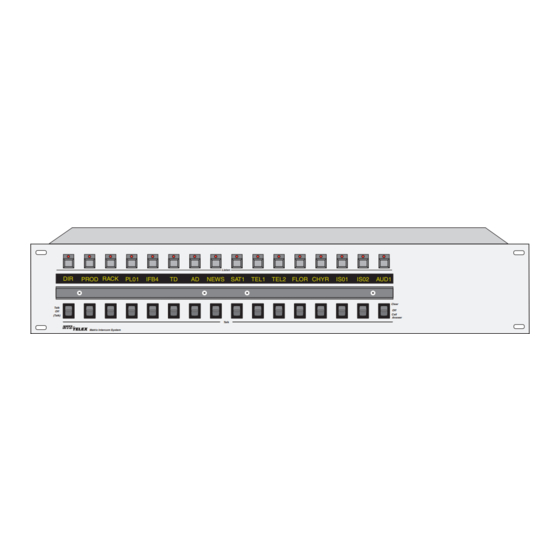
DIR PROD RACK
Talk
Off
(Talk)
BY
Matrix Intercom System
DIR
PROD RACK
Talk
Off
(Talk)
BY
Matrix Intercom System
9330-7101-001 Rev F,1/01
AND LCP-100A LEVEL CONTROL PANEL
Listen
PL01
IFB4
TD
AD NEWS SAT1
TEL1
Talk
KP96 / KP97 Keypanels
Listen
PL01
IFB4
TD
AD
NEWS
SAT1
TEL1
Talk
EKPD96 / EKPD97 Expansion Panels
LCP-100A Level Control Panel
HDST
TEL2
FLOR CHYR
IS01
IS02
AUD1
Clear
Off
Call
Answer
Incoming Messages
Programing
TEL2 FLOR CHYR
IS01
IS02
AUD1
Clear
Off
Call
Answer
NUM
PL
AUTO
1
2
3
SLIST
IFB
ISO
PREFIX
PHONE
4
5
6
Volume
RELAY
TYPE
COPY CW
E-PNL
7
8
9
Dyn Mic
EX COPY
DISP
Headset
MULT
CLR
0
PGM
FUNC
LCP-100A
Advertisement
Table of Contents

Related Manuals for RTS KP96 SERIES


Summary of Contents for RTS KP96 SERIES
-
Page 1: Installation Instructions
INSTALLATION INSTRUCTIONS KP96 / KP97 SERIES KEYPANELS WITH EKPD96 / EKPD97 EXPANSION PANELS AND LCP-100A LEVEL CONTROL PANEL ADAM™, ADAM™ CS, AND ZEUS™ INTERCOM SYSTEMS DIR PROD RACK PL01 IFB4 Talk (Talk) Matrix Intercom System PROD RACK PL01 IFB4 Talk (Talk) Matrix Intercom System 9330-7101-001 Rev F,1/01... -
Page 2: Proprietary Notice
The sole obligation of Telex during the warranty period is to pro- vide, without charge, parts and labor necessary to remedy covered defects appearing in products returned prepaid to Telex. - Page 3 End-User License Agreement for Telex® Software IMPORTANT - Please read this document carefully before using this product. THIS DOCUMENT STATES THE TERMS AND CONDITIONS UPON WHICH TELEX COMMUNICATIONS, INC. (the “COMPANY”) OFFERS TO LICENSE THE INSTALLED SOFTWARE OR PROGRAM (“the SOFTWARE”) FOR USE WITH THE PRODUCT IN WHICH IT WAS INSTALLED.
- Page 4 This page intentionally left blank. 4 Installation Instructions, KP96 / KP97 Series Keypanels...
-
Page 5: Table Of Contents
INTRODUCTION · · · · · · · · · · · · · · · · · · · · · · · · · · · · · · · · · · · · · · · · · · · · · · · · · · · · · · · · · · · · · · · NEW FEATURES FOR VERSION 8.3G . - Page 6 Figure 7. Terminal block wiring diagram for KP-96-RC option · · · · · · · · · · · · · · · · · · · · · · · · · · · · · · · ·...
-
Page 7: Introduction
FLOR CHYR Talk Headset connector. May be used instead of speaker and panel microphone. HEADSET EXPANSION SPKR ® LEVEL TELEX COMMUNICATIONS, INC. SPKR MADE IN U.S.A. OPEN MUTE KP98-7 CLOSED Choice of DE9S or RJ11 intercom connector. See “Connection to Intercom Matrix”, page 10. -
Page 8: Installation
“Basic Operation” information in the KP96 / KP97 Operating Instructions Manual. IS02 AUD1 Clear Call Answer SERIAL No. CAUTION DISCONNECT POWER BEFORE OPENING LCP-100A ® TELEX COMMUNICATIONS, INC. TELEX COMMUNICATIONS, INC. Minneapolis, MN. Minneapolis, MN. -
Page 9: Unpacking And Inspection
UNPACKING AND INSPECTION As soon as possible after receipt, inspect the container(s) and contents for physical damage that may have occurred in shipping. If damage has occurred, immediately (within 24 hours of receipt of equipment) contact the carrier in- volved and file a claim. Save all packing materials, and request an immediate inspection by the carrier’s insurance claims agent. -
Page 10: Baud Rate
• ADAM CS with RJ-11 or DB-9 back panel: You can determine the correct logical keypanel address from the worksheet in either of two ways: 1) If you know the port number that a keypanel will be connected to, look up the port number in the worksheet, then read across to the appropriate logical keypanel number for that port number. -
Page 11: Optional Connections
BELDEN 8777 IMPORTANT! When connecting to an ADAM CS back panel, use only low-profile cable connectors such as AMP Part No. 747516-3 (Telex Part No. 59926-678) Figure 4. 9-pin Intercom cable wiring diagram Table 2. 9-pin FRAME Connector Pin-out Function RS422 Data “+”... -
Page 12: Figure 6. Typical Interconnections
Adjusts Keypanel Levels EXP. DATA IN EXP. DATA OUT TERMINAL BLOCK EXTERNAL SPEAKER Figure 7. Terminal block wiring diagram for KP-96-RC option 12 Installation Instructions, KP96 / KP97 Series Keypanels LCP-100A KEYPANEL EXPANSION EXP. DATA IN EXP. DATA OUT EXPANSION PANEL CONTROL Note: Do not exceed 2 expansion panels and 3 level control panels. -
Page 13: Rear Panel Headset Connection
2.7.2 Rear Panel Headset Connection Table lists the HEADSET connector pin functions. A variety of headset types can be connected. Head- set/speaker switching can also be accomplished from this connector. When the front panel HDST switch is in the off position, shorting pins 7 and 8 on the rear panel headset connector will cause the headset to activate, and the front panel speaker and microphone will turn off. -
Page 14: Power-Up And Operational Check
There are several internal jumpers which modify keypanel operation. The jumpers are set for the following default operations: J201: The EXT LINE IN signal (KP-96-RC option only) is muted when any Talk key is pressed. May be optionally set for no mute. -
Page 15: Figure 8. Locations Of Internal Jumpers And Trimmers
J202 Q402 J401 J403 J404 J406 Figure 8. Locations of internal jumpers and trimmers Installation Instructions, KP96 / KP97 Series Keypanels 15... -
Page 16: J203 (Sidetone Muting)
The following procedures make use of the additional con- nectors available on the KP-96-RC Rear Connector Plate option. Connector pin-outs for these connectors were pre- sented earlier in this section. If the keypanel under adjust-... - Page 17 Check the level at the MIC PRE OUT connector (ref Table for pin-out). It should measure +8 dBu. 5. If the reading is not +8 dBu, but within a 3dB range, adjust the LEVEL TO MATRIX trimmer (RV406) for +8dBu. 6.
-
Page 18: Speaker/Headset Amplifier Adjustments
Headset Carbon-Mic Level Insert a -25dBm signal (1 KHz at 50 ohms) into the carbon mic input of the HEADSET connector (reference Table for pin-out). A +12 vdc bias voltage is supplied at pin 3 (carbon mic + input) of the HEADSET connector. The signal generator should be isolated from this dc bias voltage. - Page 19 Adjust RV204 (internal) for a minimum common mode signal. Insert a +8dBu (1 KHz) signal into the EXT LINE IN connector and record the output reading. 10. Remove the signal from the EXT LINE IN connector, and insert it into the audio input + and - pins of the FRAME connector, P10.
-
Page 20: Table 8. Correspondence Between Address Numbers And Intercom Port Numbers For Adam Intercom Systems
Table 8. Correspondence between address numbers and intercom port numbers for ADAM Intercom Systems Address 201 209 217 225 233 241 249 257 265 273 281 289 297 305 313 321 329 337 345 353 361 369 377 385 393 202 210 218 226 234 242 250 258 266 274 282 290 298 306 314 322 330 338 346 354 362 370 378 386 394 203 211 219 227 235 243 251 259 267 275 283 291 299 307 315 323 331 339 347 355 363 371 379 387 395... - Page 21 NOTES Installation Instructions, KP96 / KP97 Series Keypanels 21...
Need help?
Do you have a question about the KP96 SERIES and is the answer not in the manual?
Questions and answers