Table of Contents

Related Manuals for RTS DKP-12


Summary of Contents for RTS DKP-12
- Page 1 User Instructions DKP-8, DKP-12, AND KP-12 KEYPANELS PUSH-BUTTON AND LEVER KEY VERSIONS up to and including firmware version 1.05.15 DKP-8 DKP-12 9350-7497-001 Rev H KP-12 KP-12 Short April 2007...
- Page 2 OTICE The product information and design disclosed herein were originated by and are the property of Telex Communications, Inc. Telex reserves all patent, proprietary design, manufacturing, reproduction, use and sales rights thereto, and to any article dislcosed therein, except to the extent rights are expressly granted to others.
-
Page 3: Table Of Contents
READ ME FIRST ... 1 Menu List for DKP-8, DKP-12, and KP-12 Keypanels ... 3 Power-Up and Initial Settings ... 9 Applying Power ... 9 “MD1”, “Key Type” and “Set Addr” Messages ... 9 Determining the Address, CS9XXX Intercoms ... 9 Determining the Address, ADAM and ADAM CS Intercoms ... - Page 4 Menus, Autodial (for KP-12/DKP-12 Only) ... 28 Menus, KEY ASGN ... 29 Menus, KEY ASGN, General Description ... 29 Menus, KEY ASGN, AUTODIAL (For KP-12, DKP-12 Only) ... 29 Menus, KEY ASGN, AUTOFUNC ... 29 Menus, KEY ASGN, CLEAR ... 30 Menus, KEY ASGN, COPY ...
- Page 5 Menus, KEY ASGN, LISTS, UPL ... 35 Menus, KEY ASGN, LOCAL I/O (For KP-12 Only) ... 35 Menus, KEY ASGN, PHONE (For KP-12, DKP-12 Only) ... 35 Menus, KEY ASGN, REDIAL (For KP-12, DKP-12 Only) ... 36 Menus, KEY ASGN, UPL ... 36 Menus, Key Opt Menu ...
- Page 6 Determining the Keypanel Address, CS9XXX Intercoms ... 46 Determining the Keypanel Address, ADAM and ADAM CS Intercoms ... 46 Determining the Keypanel Address, Zeus Intercom Systems ... 46 Menus, SERVICE, SIDETONE ... 47 Menus, SERVICE, TALLY ... 47 Menus, SERVICE, TEST PNL ... 47 Menus, SERVICE, TONE ...
-
Page 7: Read Me First
READ ME FIRST READ ME FIRST This manual is designed for two basic types of users: 1) those who are not involved in the setup or maintenance of the key- panel, but simply want to use it to communicate; and 2) those who will use the advanced features to modify the keypanel’s operation and key assignments. -
Page 9: Menu List For Dkp-8, Dkp-12, And Kp-12 Keypanels
Menu List for DKP-8, DKP-12, and KP-12 Keypanels TOP LEVEL MENU. With the MENU indicator OFF, turn the SELECT control to view the following items in the call waiting window. MENU ITEM --- See “Top Level Menu, - - - - (Clear call waiting)”... - Page 10 Menu List for DKP-8, DKP-12, and KP-12 Keypanels PAGE 1-4 See “Top Level Menu, Page (1-4)” on page 24. TGL LISN See “Top Level Menu, TGL LISN (Toggle Listen ON/OFF)” on page 25. MENU MODE In the top level menu, tap SELECT on MENUS to turn on the MENU indicator. Then, turn SELECT to view the following See “Menu Mode”...
- Page 11 SET ADDR SIDETONE TALLY TEST PNL TONE DKP-8 Keypanel Reference View (Push-button version shown) FIGURE 1. • Although the DKP-8 has an expansion connector for connection of expansion panels and level control panels, this feature is generally not used, since the DKP-8 is a desktop unit, while expansion panels and level control panels are designed for rack mounting.
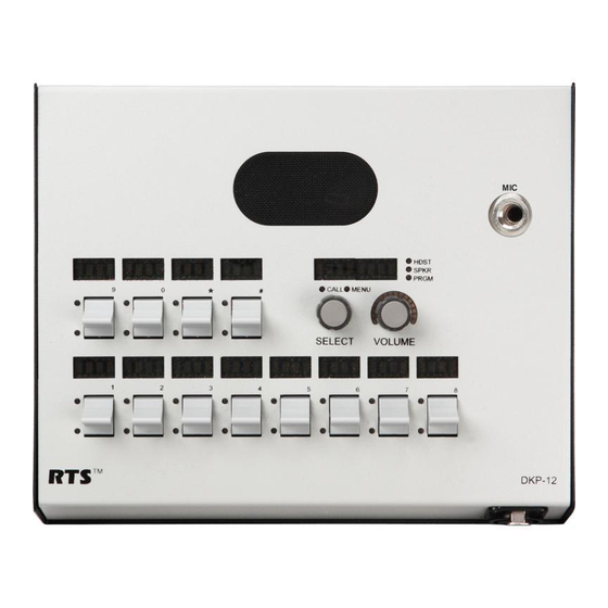
- Page 12 Although the DKP-12 has an expansion connector for connection of expansion panel and level control panels, this feature is generally not used, since the DKP-12 is a desktop unit, while expansion panels and level control panels are designed for rack mounting.
- Page 13 KP-12 Keypanel Reference View (Push-button version shown). FIGURE 3.
- Page 14 Menu List for DKP-8, DKP-12, and KP-12 Keypanels...
-
Page 15: Power-Up And Initial Settings
Applying Power Versions with an AC power connector have a power switch on the back panel. Versions with an external power supply and DC power jack do not have a power switch: plug in the power supply to apply power. “MD1”, “Key Type”... -
Page 16: Setting The Address
Power-Up and Initial Settings Setting the Address While SET ADDR is displayed, tap the SELECT control. ADDR 1 will display in the call waiting window. Turn the SELECT control to display the address (ADDR 1 through ADDR 10) that you determined above. Tap the SELECT control. -
Page 17: Specifications
Specifications Specifications MICROPHONE PREAMPLIFIER Ω Audio Input Level (at 1k Electret Mic: -42dBu, 5kΩ Dynamic Mic: 50dBu, 150Ω Output Level (to matrix): +8dBu, ±0.2dBu Max Voltage Gain, Mic to Line: 70dB, ±0.2dB Frequency Response: 100Hz to 8000 Hz, ±3dB TEST OSCILLATOR Output Level (to matrix): +8dBu, ±2dBu Output Frequency: 400Hz HEADPHONE AMPLIFIER... - Page 18 Power-Up and Initial Settings...
-
Page 19: Basic Intercom Operation
Keys and Displays • Keys that are assigned for talk or talk+listen are indicated using UPPER CASE letters in the alphanumeric displays above the keys. • Keys that are assigned for listen-only are indicated using lower case letters. • For momentary activation of a key press and hold the key. Then, release it when finished. -
Page 20: Headset/Speaker/Prgm Selection And Volume Adjustment
Basic Intercom Operation NOTE: You can adjust the amount of time that displays will flash for incoming call indication. See “Menus, SERVICE, TALLY” on page 47. Headset/Speaker/PRGM Selection and Volume Adjustment You can select operation with a headset (HDST). Or, you can select operation with the internal speaker (SPKR) and a micro- phone connected at the panel microphone jack. -
Page 21: Telephone Operation
The following paragraphs assume that a phone key has already been set up and is ready for use. If a phone key has not been set up, see “Menus, KEY ASGN, PHONE (For KP-12, DKP-12 Only)” on page 35. Names for general purpose phone keys are assigned, like any other intercom port name, using the intercom system configuration software. -
Page 22: Hanging Up
NOTE: The following paragraph assumes that a redial or autodial key has already been set up and is ready for use. To set up a redial key, see “Menus, KEY ASGN, REDIAL (For KP-12, DKP-12 Only)” on page 36. To set up an autodial key, see “Menus, KEY ASGN, AUTODIAL (For KP-12, DKP-12 Only)”... -
Page 23: Using The Top-Level Menu
General Description When the keypanel is turned ON, it resets to the top-level menu. At this level, the MENU indicator is OFF. To access the items in the top level menu, turn the SELECT control. The following items are displayed in the call waiting window as the SELECT control is turned: ITEM DESCRIPTION... -
Page 24: Top Menu Level, Call List Names
Using the Top-Level Menu Top Menu Level, Call List Names As mentioned previously, a flashing CALL indication occurs when there is an incoming call from a destination and there is no key assigned to talk back to that destination. The destination name flashes in the call waiting window and is added to the call list. -
Page 25: Top Level Menu, Display, Key Icom
Top Level Menu, Display Top Level Menu, Display, KEY ICOM When you select KEY ICOM, the intercom system names for all talk key assignments will appear in the display above the intercom keys. If there is only one intercom system, the word “LOCL” will display to indicate “local intercom”. The call waiting window will also display TAP KEYS. -
Page 26: Top Level Menu, Display, Listen
Using the Top-Level Menu Top Level Menu, Display, Listen When you tap LISTEN, the listen key assignment for each key will appear in the alphanumeric display above the key. If there is no listen assignment, the display will show (- - - -). The call waiting window will also display TAP KEYS. -
Page 27: Top Level Menu, Key List
Top Level Menu, Key List Top Level Menu, Key List When you select Key List, the list of all currently assigned keys on all 4 setup pages will be scrollable in the call waiting win- dow. Turn the SELECT control to locate a key assignment. To talk to the selected key assignment, press and hold the SELECT control. -
Page 28: Top Level Menu, Lists, P-P (Point-To-Point)
Using the Top-Level Menu • If restrictions against key assignment have been imposed using the intercom system configuration software, the intercom key may ignore the assignment. In this case, contact the intercom system administrator if you need to make a change. •... -
Page 29: Top Level Menu, Lists, Iso
Top Level Menu, Lists To talk to the selected IFSL, press and hold the SELECT control. This will also add the IFSL name to the call list for future use. To assign the IFSL to an intercom key for future use, press and hold the SELECT control, then tap an intercom key. •... -
Page 30: Top Level Menu, Lists, Upl
Using the Top-Level Menu To talk to the selected special list, press and hold the SELECT control. To assign the special list to an intercom key for future use, press and hold the SELECT control, then tap an intercom key. •... -
Page 31: Top Level Menu, Tgl Lisn (Toggle Listen On/Off)
Top Level Menu, TGL LISN (Toggle Listen ON/OFF) options did not stay with keys as setup pages were change. This meant that if you changed setup pages, the key assignments on the new active setup page would take on the key options from the previously used setup page. Starting with version 24, this has been changed so that key options now track not only the keys to which they are assigned, but also the setup page. - Page 32 Using the Top-Level Menu...
-
Page 33: Menu Mode
Select Control Operation in Menu Mode • The keypanel normally operates at the top-level menu. At this level, the MENU indicator is OFF. To enter menu mode, turn the SELECT control to display MENUS, then tap the SELECT control. The MENU indicator will turn ON. NOTE: If your keypanel displays (MENUS) instead of MENUS, this indicates that menu mode has been locked, and you must enter the 4-digit passcode that was saved previously to gain access. -
Page 34: Menus, Autodial (For Kp-12/Dkp-12 Only)
LOCAL I/O and OPTO-ISO are available only with the optional GPI module installed (KP-12 only). Menus, Autodial (for KP-12/DKP-12 Only) NOTE: This menu is used to store autodial numbers. To assign a key that dials a specific autodial number, see page 29. To use stored autodial numbers with an all-purpose phone key see page 16. -
Page 35: Menus, Key Asgn
NOTE: To store phone number for use by autodial keys, see “Menus, Autodial (for KP-12/DKP-12 Only)” on page 28. When you select AUTODIAL, the point-to-point scroll list will display for the currently selected intercom system. -
Page 36: Menus, Key Asgn, Clear
Menu Mode • Auto-function key assignment changes are automatically uploaded to the intercom system and saved to the online configuration. Double-tap the SELECT control to return to the previous menu level. Or, press and hold the SELECT control for two seconds to exit the menu mode. -
Page 37: Menus, Key Asgn, Lists
Menus, KEY ASGN To copy the TALK assignment, turn the SELECT control to display TALK, then tap SELECT. TAP DEST will appear in the call waiting window. Tap the destination key (the key you want to copy to). The call waiting window will display LISTEN. To assign the new key as LISTEN, tap SELECT. -
Page 38: Menus, Key Asgn, Lists
Menu Mode Menus, KEY ASGN, LISTS General Description This menu gives you complete control when setting up key assignments. You can assign keys for any of the types of operations listed in Table 3 on page 31. Menus, KEY ASGN, LISTS, ICOM ICOM is only selectable for trunked systems. -
Page 39: Menus, Key Asgn, Lists, Ifsl
Menus, KEY ASGN Changing a key’s assignment has no effect on any key options that may already be assigned to that key using “General Description” on page 37. Double-tap the SELECT control to return to the previous menu level. Or, press and hold the SELECT control for two seconds to exit menu mode. -
Page 40: Menus, Key Asgn, Lists, Rly (Relays)
Menu Mode Tap SELECT. The call waiting window will display TAP KEY. Tap an intercom key to assign the party line. If restrictions against key assignments have been imposed using the intercom system configuration software, the intercom key may ignore the key assignment. In this case, contact the intercom system administrator if you need to make a change. P-P key assignment has no effect on any key options that may already be assigned to that key using “General Description”... -
Page 41: Menus, Key Asgn, Lists, Upl
An intercom key must already have one of the following key assignments in order for a Local I/O assignment to function: IFB, ISO, PL, P-P, or SPCL. Menus, KEY ASGN, PHONE (For KP-12, DKP-12 Only) You use this menu item to assign a general purpose phone key that can be used for manual dialing, auto-dialing or redialing. A... -
Page 42: Menus, Key Asgn, Redial (For Kp-12, Dkp-12 Only)
SERVICE, SAVE CFG” on page 46.. Otherwise, the phone function will be lost when the keypanel is turned OFF. Menus, KEY ASGN, REDIAL (For KP-12, DKP-12 Only) You use this menu item to assign a redial key for use along with one or more phone keys. If the KP-12 has multiple phone keys assigned, the redial key redials the last number dialed on the last phone key that was used. -
Page 43: Menus, Key Opt Menu
Menus, Key Opt Menu Tap the intercom key that you want to assign the UPL. The name UPL will appear in the display above the key. If restrictions against key assignments have been imposed using the intercom system configuration software, the intercom key may ignore the assignment. -
Page 44: Menus, Key Opt, Clr Opt
Menu Mode Turn the SELECT control to display CHIME2 or CHIME3 if desired, then tap SELECT. You will hear an audible sample of the chime tone. The call waiting window will also display TAP KEYS. Tap any keys you want to assign the chime tone to for incoming calls. Double-tap the SELECT control to return to the previous menu level. -
Page 45: Menus, Key Opt, Latching
Menus, Key Opt Menu Tap the intercom key that will be the group master key. The talk and listen indicators for the selected key will flash green, depending on whether talk, listen, or both are currently setup on the key. This confirms the group master assignment. NOTE: You cannot assign group operation to any key that is programmed for solo operation (described below) or that is locked ON or OFF using button lock. -
Page 46: Menus, Service Menu
Menu Mode Menus, SERVICE MENU General Description Use this menu to set the logical keypanel address during installation and to set general operating features such as display brightness, etc. Any changes you make in this menu must be saved locally if you want them to be retained for future use. Oth- erwise, the settings will be lost when the keypanel is turned OFF. -
Page 47: Menus, Service, Mic Ctrl
Menus, SERVICE MENU Select MENUS, SERVICE, LOCK. The call waiting window will display TAP CODE. Enter a 4-digit passcode by tapping intercom keys. When the last digit is entered, all displays will briefly display asterisks while the passcode is being stored, then the keypanel will reset to the top level menu. -
Page 48: Menus, Service, Mic Gain
MODS are used. If you need to assign MODS on a DKP keypanel, simply refer to the “Procedure to Assign MODS”, and set MODS 1 and 2 (DKP-8) or 1-3 (DKP-12) as summarized in Table 4 . The KP-12 keypanel, on the other hand, can be used with various combinations of expansion panels and level control panels. -
Page 49: Procedure To Assign Mods
Menus, SERVICE MENU Default Module Number Assignments TABLE 4. Keypanel/LCP-12 Default MODE Assignments MOD 6 Keys 21-24 MOD 7 Keys 25-28 EKP-16/LCP-16 Default MOD Assignments MOD 5 Keys 17-20 MOD 6 Keys 21-24 MOD 7 Keys 25-28 MOD 8 Keys 29-32 EKP-20/LCP-20 Default MOD Assignments MOD 5 Keys 17-20... -
Page 50: Using Multiple Expansion Panels (Kp-12 Only)
Menu Mode Using Multiple Expansion Panels (KP-12 Only) When using multiple expansion panels, some MOD numbers may have to be reassigned so that each group of 4 keys has its own unique MOD number. Table X shows the correspondence between MOD numbers, key numbers, and setup pages. Example 1, connecting one EKP-20 along with a KP-12. -
Page 51: Menus, Service, Opto-Iso (Kp-12 With Gpi Module Only)
Menus, SERVICE MENU After selecting MUTE LVL, turn the SELECT control to select either HDPHONE or SPEAKER, then tap SELECT again. The current muting level will display in the call waiting window. Turn the SELECT control to adjust the mute level from -40dB (maximum muting) to 0dB (no muting). Double-tap the SELECT control to return to the previous menu level. -
Page 52: Menus, Service, Out Ctrl
Menu Mode OPTO-ISO Assignment Options (KP-12 with GPI Module Only) TABLE 6. Name Description PAGE 3 Assigns input to actuate setup page 3 PAGE 4 Assigns input to actuate setup page 4 Menus, SERVICE, OUT CTRL OUT CTRL gives you the choice to listen to audio through either HEADSET or SPEAKER no matter what MIC is selected on the front of the keypanel. -
Page 53: Menus, Service, Sidetone
Menus, SERVICE MENU Setting the Keypanel Address While SET ADDR is displayed, tap the SELECT control. ADDR 1 will appear in the call waiting window. Turn the SELECT control to display the desired logical keypanel address (ADDR 1 through ADDR 10) then tap the SELECT control. -
Page 54: Menus, Service, Tone
Menu Mode • The call waiting window will display TAP KEYS. If you tap any intercom key, the display above that key will briefly display OK. If you turn either the SELECT or VOLUME control, the alphanumeric display above the control will increment or decrement by ones at each detente. - Page 55 Table 7: Correspondence between ADDR numbers and intercom port numbers for ADAM and ADAM CS Intercom Systems Settings for ADDR Intercom Port Numbers...
- Page 56 Table 7: Correspondence between ADDR numbers and intercom port numbers for ADAM and ADAM CS Intercom Systems Settings for ADDR Intercom Port Numbers 1000...
-
Page 57: Kp-12 Audio Transmit Board Connections
KP-12 Audio Transmit Board Connections The new audio transmit board (9030-7725-500), if used with the new controller board (9030-7725-000) has digital control for compression setting and Mic gain setting through the master volume encoder of the KP-12. By inspecting the audio transit board, the following pots, jumpers and connectors are identified: R16 and R142 are attenuation pots for the Matrix Out and Preamp Out, respectively. - Page 58 IMPORTANT! - If you are using an earlier model KP-12, and your audio transmit board needs to be replaced, you will need to make the following adjustments with the new audio transmit board for it to work properly. There are four jumpers on the audio transmit board (9030-7725-500) - JP1, JP2, JP3, and JP4. •...
-
Page 59: Replacing The Kp-12 Power Supply
Replacing the KP-12 Power Supply These instructions explain how to replace the old KP-12 power supply (part number 352024-000) with the new power supply (part number 532088-000). Included in this kit: • Power Supply - part number 532088-000 • 3 metal tabs - part number 702156-000 •... - Page 60 NOTE: If you have an older chassis, you will need to attach the 3 metal tabs as shown in the figure below. You will also need to use the supplied washer on the screw hole with no metal tab (the washer goes between the board and the chassis hole). If you have a new chassis, you can discard the metal tabs and washer.
- Page 62 12000 Portland Avenue South • Burnsville, MN 55337 • U.S.A...
Need help?
Do you have a question about the DKP-12 and is the answer not in the manual?
Questions and answers