GeoVision GV-IP Decoder Box Series User Manual
Full hd 1080p hdmi
Hide thumbs
Also See for GV-IP Decoder Box Series:
- Quick start manual (26 pages) ,
- User manual (80 pages)

Subscribe to Our Youtube Channel
Related Manuals for GeoVision GV-IP Decoder Box Series


Summary of Contents for GeoVision GV-IP Decoder Box Series
- Page 1 GV-IP Decoder Box Series and GV-Pad Mini User’s Manual Before attempting to connect or operate this product, please read these instructions carefully and save this manual for future use. DB-Pad-UM-B...
- Page 2 Every effort has been made to ensure that the information in this manual is accurate. GeoVision, Inc. makes no expressed or implied warranty of any kind and assumes no responsibility for errors or omissions. No liability is assumed for incidental or consequential damages arising from the use of the information or products contained herein.
- Page 3 Preface Welcome to the GV-IP Decoder Box and GV-Pad Mini User’s Manual. This Manual is designed for the following models and firmware versions: Model Firmware Version GV-IP Decoder Box Lite V1.0 GV-IP Decoder Box Plus V1.02 GV-IP Decoder Box Ultra V1.0 GV-Pad Mini V1.01...
- Page 4 After purchasing a new GV-IP camera or factory resetting your GV-IP camera, you need to set up a login username and password for that camera. Download and install GV-IP Device Utility from GeoVision’s website. On the GV-IP Device Utility window, click Search to search for your GV-IP cameras.
- Page 5 Optionally click Upgrade all devices to use the same username and password on all other cameras.
-
Page 6: Table Of Contents
1.8.2 GV-Pad Mini ................... 17 1.9 GV-IR Remote Control................... 20 Chapter 2 Getting Started....................22 2.1 Installing the GV-IP Decoder Box Series..............22 2.2 Connecting the GV-IP Decoder Box Series............23 2.3 Connecting the GV-Pad Mini.................. 25 2.4 The Main Screen ....................26 2.5 Setting Up the Network.................. - Page 7 4.3 Date & Time......................50 4.4 Account ........................51 4.5 Display ........................53 4.6 Camera........................54 Chapter 5 Advanced Applications ..................55 5.1 Upgrading the Firmware ..................55 5.1.1 Upgrading Firmware through a Storage Device ........55 5.1.2 Upgrading Firmware through GV-IP Device Utility........56 5.2 Restoring Default Settings ..................58...
-
Page 8: Chapter 1 Introduction
GV-Joystick V2 can be installed to control GeoVision and third-party PT / PTZ / Speed Dome cameras. The IP Devices and GV-Software that Can Connect with GV-IP Decoder Box Ultra... -
Page 9: Features
1.1.1 Features Decode video streams in H.264 / H.265 codec up to 30 fps Decode up to 8 megapixel IP cameras Decode up to 64 IP streams Automatically search for ONVIF IP devices Support for third-party IP cameras that adhere to RTSP or ONVIF ... -
Page 10: Gv-Ip Decoder Box Plus
DVR and PC setup. The security administrator can monitor channels, take snapshots of critical moments, and pause at a channel when events occur. GV-Joystick V2 can be installed to control GeoVision and third-party PT / PTZ / Speed Dome cameras. -
Page 11: Features
1.2.1 Features Decode video streams in H.264 codec at up to 30 fps Decode up to 4 megapixel IP cameras Decode up to 64 IP streams Automatically search for ONVIF IP devices Support for third-party IP cameras that adhere to RTSP or ONVIF ... -
Page 12: Gv-Ip Decoder Box Lite
GV-Joystick V2 can be installed to control GeoVision and third-party PT / PTZ / Speed Dome cameras. The IP Devices that Can Connect with GV-IP Decoder Box Lite... -
Page 13: Features
1.3.1 Features Decode video streams in H.264 codec at up to 30 fps Decode up to 2 megapixel IP cameras Decode up to 16 IP streams Automatically search for ONVIF IP devices Support for third-party IP cameras that adhere to ONVIF ... -
Page 14: Gv-Pad Mini
DVR and PC setup. The security administrator can monitor channels, take snapshots of critical moments, and pause at a channel when events occur. GV-Joystick V2 can be installed to control GeoVision and third-party PT / PTZ / Speed Dome cameras. - Page 15 1.4.1 Features Decode video streams in H.264 codec at up to 30 fps Decode up to 4 megapixel IP cameras Decode up to 64 IP streams Automatically search for ONVIF IP devices Support for third-party IP cameras that adhere to RTSP or ONVIF ...
-
Page 16: Compatible Devices
Introduction 1.5 Compatible Devices The compatible devices for GV-IP Decoder Box Series and GV-Pad Mini vary according to different models. GV-IP Decoder Box Ultra 1. GV-IP Camera and GV-Video Server using H.264 / H.265 codec 2. Third-party IP devices that support H.264 / H.265 and adhere to RTSP or ONVIF 3. - Page 17 Note: 1. GV-Mobile Server is an application that encodes up to 64 video channels and subsequently allows the GV-IP Decoder Box Ultra / Plus / GV-Pad Mini to decode and display: analog cameras and IP cameras connected to GV-DVR / NVR / VMS ...
-
Page 18: Packing List
Introduction 1.6 Packing List GV-IP Decoder Box Ultra GV-IP Decoder Box Ultra GV-IR Remote Control Download Guide Warranty Card GV-IP Decoder Box Plus GV-IP Decoder Box Plus AC/DC Adapter (12 V, 3 A, 36 W) Power Cord USB Mouse Download Guide Warranty Card GV-IP Decoder Box Lite GV-IP Decoder Box Lite... -
Page 19: Optional Accessories
Small screws x 4 GV-Joystick V2 GV-Joystick V2 facilitates focusing, zooming, panning, and tilting of GeoVision and third-party PT, PTZ, and Speed Dome cameras on GV-IP Decoder Box Series / GV-Pad Mini. GV-Joystick V2 USB Type A to Type B Cable ... -
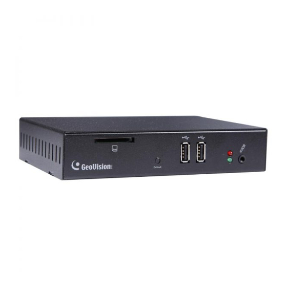
Page 20: Overview
Introduction 1.8 Overview 1.8.1 GV-IP Decoder Box Series 1.8.1.1 Front View GV-IP Decoder Box Ultra Figure 1-5 No. Name Function Micro SD Card Connect to a micro SD card for local storage of snapshots and firmware upgrade. Slot The red LED indicates the power is supplied. - Page 21 GV-IP Decoder Box Plus Figure 1-6 GV-IP Decoder Box Lite Figure 1-7 No. Name Function SD Card Connect to a SD card for local storage of snapshots and firmware upgrade. Only supported by GV-IP Decoder Box Plus. Slot Reset the device to the default factory settings. Use a pin to press the Default default button for about 10 seconds.
-
Page 22: Rear View
Introduction 1.8.1.2 Rear View GV-IP Decoder Box Ultra Figure 1-8 No. Name Function DC 12V Connect to power by using the supplied power adapter. Audio Out Connect to a speaker. HDMI Connect to an HDMI-compliant display device. Connect to a GV-Joystick V2, USB mouse, or USB storage USB 2.0 device. - Page 23 GV-IP Decoder Box Plus / Lite Figure 1-9 No. Name Function Network Connect to the network. Audio Out Connect to a speaker. Connect to a VGA monitor. HDMI Connect to an HDMI-compliant display device. Connect to a GV-Joystick V2, USB mouse, or USB storage device. DC 12V Connect to power by using the supplied power adapter.
-
Page 24: Gv-Pad Mini
Introduction 1.8.2 GV-Pad Mini 1.8.2.1 Front and Rear Views Figure 1-10 No. Name Function LCD screen Display the system settings of the device. Speaker Listen to the audio around the connected IP device. Ethernet Port Connect to the network. Stand Position the GV-Pad Mini to your preference. - Page 25 1.8.2.2 Top, Left-Side and Right-Side Views Figure 1-11 No. Name Function Micro SD Card Connect to a micro SD card for local storage of content and firmware upgrade. Slot The red LED indicates the power is supplied. LED Indicators The green LED indicates the system is ready. Press to enter the Standby/Sleep mode.
- Page 26 Introduction No. Name Function DC 12V Connect to power using the supplied power adapter. Connect to a GV-Joystick V2, USB mouse, or USB storage device for local storage of content and firmware upgrade. Line Out Port Connect to a headphone or speaker. Reset the device to the default settings.
-
Page 27: Gv-Ir Remote Control
1.9 GV-IR Remote Control The GV-IR Remote Control is only supported by GV-IP Decoder Box Ultra. Figure 1-12 No. Name Function Back Return to the previous page in the Main Screen. Menu Control Move up, down, right and left in the Main Screen. Volume Control Increase or decrease the volume. - Page 28 Introduction No. Name Function Use the following hotkeys to execute commands when a camera live view is selected in the main screen. CH1: Take a screenshot Hotkeys CH2: Activate the PTZ function. CH3: Enter in full screen mode. CH4: Activate the audio out function. PTZ Controls No.
-
Page 29: Chapter 2 Getting Started
Chapter 2 Getting Started 2.1 Installing the GV-IP Decoder Box Series You can install the GV-IP Decoder Box Series on the wall or simply use it as desk mount device. Wall Mount Installation For wall mount installation, you need to purchase the wall mount kit. -
Page 30: Connecting The Gv-Ip Decoder Box Series
Getting Started 2.2 Connecting the GV-IP Decoder Box Series Follow the steps below to connect the GV-IP Decoder Box Series. Here we use GV-IP Decoder Box Plus as an example. Figure 2-3 1. Connect the device to the LAN port using an RJ-45 cable. - Page 31 Note: 1. You can only connect the GV-IP Decoder Box Series to one display device through either the HDMI or VGA connector. 2. The default video output is set to HD 720P resolution. If you use a VGA monitor, be sure to change the output resolution to VGA 1024 x 768.
-
Page 32: Connecting The Gv-Pad Mini
Getting Started 2.3 Connecting the GV-Pad Mini Follow the steps below to connect GV-Pad Mini. Figure 2-4 1. Connect the device to the LAN port using an Ethernet cable. 2. Connect to power using the supplied power adapter. 3. Connect a speaker / headphone to the line out port if needed. 4. -
Page 33: The Main Screen
2.4 The Main Screen After you have connected the necessary wires and cables, GV-IP Decoder Box Series / GV-Pad Mini will power on and the main screen will display on the monitor. Note: The user interfaces are different by models. Find the relevant settings corresponding to your device. -
Page 34: Setting Up The Network
DHCP server without further settings. To change the IP address to a fixed one, follow the steps below. Note: By default, if GV-IP Decoder Box Series / GV-Pad Mini is connected to LAN without the DHCP server, it will be assigned a static IP address: 192.168.0.100. - Page 35 Tip: You can also use GV-IP Device Utility downloaded from GeoVision’s website. to modify the IP address by clicking the GV-IP Decoder Box Series / GV-Pad Mini and selecting Configure. Note the compatible versions of GV-IP Device Utility for the following products: ...
-
Page 36: Adding Ip Devices To Live View Grid
2.6 Adding IP Devices to Live View Grid Before you start, make sure all the IP devices or GV-Mobile Server is under the same LAN as GV-IP Decoder Box Series / GV-Pad Mini. 2.6.1 Adding IP Devices through Automatic Search 1. - Page 37 4. Click Save to apply. Note: All the GeoVision IP devices have the default user name and password of admin. If you want to change the default settings, you may change the user name and password under Camera in System Settings (see 4.6 Camera).
- Page 38 Getting Started 6. Drag and drop an IP device from the camera list to the grid. To select multiple cameras at a time, click Select Multiple Cameras on the top. Figure 2-11 7. To adjust the display order of the cameras, right-click the camera and click Move Up or Move Down.
-
Page 39: Adding Ip Devices Manually
2.6.2 Adding IP Devices Manually If the GV-IP Decoder Box Series / GV-Pad Mini is unable to detect the IP device using the search function, you can search for the device manually. 1. Click the Camera / IPCam Search icon on the main page. - Page 40 4. Click Save. The IP device is now added to the camera list. Note: All the GeoVision IP devices have the default user name and password of admin. If you want to change the default settings, you may change the user name and password...
-
Page 41: Adding Devices Using Gv-Ip Device Utility
Note: The compatible version of GV-IP Device Utility must be V8.6.6.0 or later for GV-Pad Mini and V8.7.2.0 or later for GV-IP Decoder Box Ultra. Before you start, make sure that all the IP devices / software must be under the same LAN as the GV-IP Decoder Box Series / GV-Pad Mini. Figure 2-13... -
Page 42: Adding A Gv-Ip Device
Device Utility window appears, it will automatically search for all the GV-IP Devices under the same LAN. Figure 2-14 2. Click the IP address of your GV-IP Decoder Box Series / GV-Pad Mini and select Connect Setting. This dialog box appears. Figure 2-15... - Page 43 3. Type the ID and password of your GV-IP Decoder Box Series / GV-Pad Mini and click OK. The default ID and password are admin. This window appears. Figure 2-16 4. Use the Camera List toolbar to add, remove, or configure a selected camera in the Camera List.
- Page 44 Getting Started D. If you have changed the default ID and password of the added GV-IP Devices / GV-Mobile Server, right-click the channel, select Edit and type the username and password to log in for connection. By default, the login ID and password for all GV-IP Devices are admin.
-
Page 45: Adding A Third-Party Device
2.7.2 Adding a Third-party Device 1. Click the Add Camera button on the Video Connection Setting window (Figure 2-16). This dialog box appears. Figure 2-18 2. Type the IP address, user name, and password of the device. 3. Select Protocol for Brand and one of the following protocols for Device Name. Type the RTSP command if required. - Page 46 Getting Started ONVIF: Select this protocol if your camera adheres to ONVIF. RTSP over HTTP: The RTSP protocol uses an HTTP port for data streaming from the IP camera. RTSP over TCP: The RTSP protocol uses a TCP port for data streaming from the IP camera.
-
Page 47: Chapter 3 Accessing Live View
Chapter 3 Accessing Live View 3.1 Live View After adding and assigning IP devices to the live view grid, the camera live views are displayed on the main screen. Right-click a live view grid to access the following options: Note: The user interfaces are different by models. Find the relevant settings corresponding to your device. - Page 48 Accessing Live View Capture Snapshot: Only supported by GV-IP Decoder Box Ultra / Plus / GV-Pad Mini, capture a snapshot of the live view. This option is only available when the live view grid is not looping. See 3.2 Capturing Snapshots. Play Mode: When more than one device is added to a grid, select Loop to start looping ...
- Page 49 When the device resolution exceeds the maximum resolution supported, GV-IP Decoder Box Series / GV-Pad Mini will connect to stream 2 of the device instead. If stream 2 is unavailable, the message “Resolution Error” will appear on the screen.
- Page 50 Accessing Live View GV-IP Decoder Box Ultra Screen Division Maximum Resolution Fisheye Dewarping 1-Division (Single View) 3840 x 2160 Grid 1 2560 x 1920 4-Division (Quad View) Other 3 Grids 1920 x 1080 Not supported 8-Division 1280 x 720 for each grid 1280 x 720 for each grid 9-Division GV-IP Decoder Box Plus...
-
Page 51: Capturing Snapshots
3.2 Capturing Snapshots You can take snapshots of the live view and the snapshots will be automatically saved to the selected storage device (USB drive or SD card) in JPEG format. Before you start, be sure: You have inserted a USB drive or SD card for storage. ... -
Page 52: Fisheye Dewarping
Accessing Live View 3.3 Fisheye Dewarping You can enable fisheye dewarping if the fisheye camera is in Single View or Grid 1 of the Quad View. Right-click the live view of the fisheye camera and select Fisheye to enable fisheye dewarping. Note: Fisheye dewarping is only supported by GV-IP Decoder Box Plus. -
Page 53: Controlling Ptz And Speed Dome Cameras With Gv-Joystick V2
3.4 Controlling PTZ and Speed Dome Cameras with GV-Joystick V2 The GV-Joystick V2 can be connected to the GV-IP Decoder Box Series / GV-Pad Mini to control GeoVision PT, PTZ, and Speed Dome cameras, and also third-party PTZ and Speed Dome cameras. -
Page 54: Chapter 4 System Settings
System Settings Chapter 4 System Settings On the main screen, click the System Settings icon to access the following setting pages: System, Network, Date & Time, Account, Display, and Camera. Note: The user interfaces are different by models. Find the relevant settings corresponding to your device. -
Page 55: System
4.1 System On the System page, you can change the device name, interface language, resolution, or the designated storage device for storing snapshots. Note: Capturing snapshots is not supported by GV-IP Decoder Box Lite. Figure 4-2... - Page 56 Language: Select a language for the user interface. Resolution: Only for GV-IP Decoder Box Series, select a resolution for your monitor. The default is HD 720P. If you are using a VGA monitor, select VGA 1024 x 768.
-
Page 57: Network
4.2 Network To configure the network settings for the GV-IP Decoder Box Series / GV-Pad Mini, see 2.5 Setting Up the Network. 4.3 Date & Time On the Date & Time page, you can configure the date and time of the GV-IP Decoder Box Series / GV-Pad Mini. -
Page 58: Account
System Settings 4.4 Account On the Account page, you can configure the login account of the GV-IP Decoder Box Series / GV-Pad Mini. The default user name and password are both admin. You will need the login information if you want to access the GV-IP Decoder Box Series / GV-Pad Mini through GV-IP Device Utility. - Page 59 Configure the lock function by enabling Lock Operation (for GV-IP Decoder Box Ultra) / Login window (for GV-IP Decoder Box Plus / Lite / GV-Pad Mini) to manage users’ accessibility. Once you enable the function, you must enter the User Name and Password if you have been idle for a specified time period.
-
Page 60: Display
System Settings 4.5 Display On the Display page, you can specify what information to overlay on the live view. Figure 4-5 Font Color: Change the font color of the text overlay. Device Name / Display Name: Select to display the device name of the camera. ... -
Page 61: Camera
4.6 Camera On the Camera page, you can change the ID and password of the IP device, which automatically applies to all IP devices. The default ID and Passwords are admin. Click Save to apply the settings. Figure 4-6... -
Page 62: Chapter 5 Advanced Applications
3. On the main screen, click the Firmware Update icon. 4. Select the storage device and select the firmware file. Figure 5-1 5. Click Update to begin upgrading the firmware. The GV-IP Decoder Box Series / GV-Pad Mini will restart after the firmware upgrade is completed. -
Page 63: Upgrading Firmware Through Gv-Ip Device Utility
5.1.2 Upgrading Firmware through GV-IP Device Utility 1. Run the GV-IP Device Utility. All GV-IP Devices under the same LAN are searched. Figure 5-2 2. Click the IP address of your GV-IP Decoder Box Series / GV-Pad Mini and select Configure. This window appears. Figure 5-3... - Page 64 4. Click Upgrade to start upgrading. The system will restart itself when the upgrade is completed. Note: The default user name and password are both admin. To see how to change the login information of GV-IP Decoder Box Series / GV-Pad Mini, refer to 4.4 Account.
-
Page 65: Restoring Default Settings
5.2 Restoring Default Settings If for any reason the GV-IP Decoder Box Series / GV-Pad mini is not responding correctly, there are two ways to restore the device to default settings. 1. Use the pin to press the load default button on the front / side panel for about 10 seconds. - Page 66 Advanced Applications For GV-IP Decoder Box Plus / Lite / GV-Pad Mini, click the System Settings icon on the main screen and click the Load Default button on the bottom of any of the setting pages. Figure 5-6 The system will restore default settings and reboot itself.
Need help?
Do you have a question about the GV-IP Decoder Box Series and is the answer not in the manual?
Questions and answers