
Related Manuals for GeoVision GV-PBL8800


Summary of Contents for GeoVision GV-PBL8800
- Page 1 GV-IP Panoramic Cameras User's Manual GV-PBL8800 GV-PDR8800 Before attempting to connect or operate this product, please read these instructions carefully and save this manual for future use. MPA-UM-A...
- Page 2 GeoVision. Every effort has been made to ensure that the information in this manual is accurate. GeoVision, Inc. makes no expressed or implied warranty of any kind and assumes no responsibility for errors or omissions. No liability is assumed for incidental or consequential damages arising from the use of the information or products contained herein.
-
Page 3: Preface
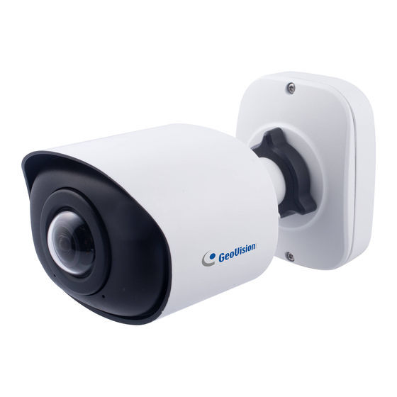
The features described in the manual vary among camera models and versions. Some features may not be available in your camera. This manual is designed for the following camera models: Model Model Number Panoramic IR Fixed Bullet IP Camera GV-PBL8800 Panoramic IR Fixed Rugged IP Dome GV-PDR8800... -
Page 4: Table Of Contents
Table of Contents Preface ............................ 1 Chapter 1. Introduction ......................1 Safety Instruction ........................... 1 Chapter 2. Product Description ................... 2 Product Overview ....................... 2 Key Features ........................2 System Requirements ......................4 Chapter 3. Configuration Flow ..................... 5 Chapter 4. Network Connection ................... 7 Setting the Camera over the LAN .................. - Page 5 8.5.4 Maintenance ............................144...
-
Page 6: Chapter 1. Introduction
Chapter 1. Introduction Safety Instruction These instructions are intended to ensure that user can use the product correctly to avoid danger or property loss. The precaution measures are divided into “Warnings” and “Cautions” Warnings: Serious injury or death may be caused if any of these warnings is neglected. •... -
Page 7: Chapter 2. Product Description
Chapter 2. Product Description 2.1 Product Overview GeoVision provides a consistent range of cost-effective and reliable network cameras to fully meet your requirements. Based on embedded Linux operating system, GeoVision’s panoramic IP camera series could be easily accessed and managed either locally or remotely with great reliability. - Page 8 Video • H.265/ H.264/ MJPEG video compression capability • Support Primary Stream/ Secondary Stream/ Tertiary Stream • Support Smart Stream by 10-level adjustable H.265+ • Bandwidth saved by Smart Stream with stable network connection • Real-time video electronic amplification Audio •...
-
Page 9: System Requirements
2.3 System Requirements Operating System: Windows XP/Vista/7/8/10/11 CPU: 1.66GHz or higher RAM: 1G or higher Graphic memory: 128MB or more Internet protocol: TCP/IP (IPv4/IPv6) Web Browsers: Internet Explorer 8.0 and above version, Mozilla Firefox, Google Chrome and Safari. -
Page 10: Chapter 3. Configuration Flow
Chapter 3. Configuration Flow The configuration flow of cameras is shown in the following figure. Note: The configuration must be based on the actual situation of different models. More configuration details are shown in the following table. - Page 11 Table 1. Description of flow Configuration Description Reference Connect the network camera. You can set the 4.1 Setting the Camera over Network Connection camera over the LAN or the LAN dynamic IP connection. Accessing from IP Accessing the Network address, web browser 5.1 Assigning An IP Camera and back-end software...
-
Page 12: Chapter 4. Network Connection
Chapter 4. Network Connection 4.1 Setting the Camera over the LAN Connecting the camera to a switch or a router is the most common connection method. The camera must be assigned an IP address that is compatible with its LAN. 4.1.1 Connect via a Switch or Router Refer to the following figure to set network camera over the LAN via the switch or router. -
Page 13: Dynamic Ip Connection
4.2 Dynamic IP Connection Step 1: Connect the network camera to a router; Step 2: On the camera, assign a LAN IP address, the Subnet mask and the Gateway; Step 3: On the router, set port forwarding. E.g. 80, 8000 and 554 ports. The steps for port forwarding vary depending on different routers. -
Page 14: Chapter 5. Accessing The Network Camera
Chapter 5. Accessing the Network Camera 5.1 Assigning an IP Address The Network Camera must be assigned an IP address to be accessible. The default IP address of the network camera is 192.168.0.10. You can change the IP address of the camera via GV-IP Device Utility, via browser, or from the web browser. -
Page 15: Assigning An Ip Address Via Browser
5.1.2 Assigning an IP Address via Browser Follow the steps to change the IP address of the camera via browser: Step 1: Change the IP address of computer to 192.168.0.10 segment, here are two ways as below: a. Start → Control Panel → Network and Internet Connection → Network Connection → Local Area Connection, and double click it;... - Page 16 b. Click “Advanced”, and then click “IP settings”--> “IP address”--> “Add”. In the pop-up window, enter an IP address that in the same segment with the camera (e.g. 192.168.0.60), but please note that this IP address shall not conflict with the IP address on the existing network);...
- Page 17 Step 3: You need to set the password first when using it for the first time. And you can also set three security questions for your device after activation. Then you can log in to the camera with the default user name (admin) and a custom password. Note: •...
-
Page 18: Accessing From The Web Browser
5.2 Accessing from the Web Browser The camera can be used with the most standard operating systems and browsers. And the camera was upgraded to support Plugin-Free Mode. In Plugin-Free Mode, you can preview the video on the browser without plugin. Currently Plugin-Free Mode is supported in Firefox &... -
Page 19: Chapter 6. Live View
Chapter 6. Live View 6.1 Live Video After logging in the network camera web GUI successfully, user is allowed to view live video as follows. Table 2. Description of the buttons Parameter Description Click to access the live view page. Live Video Click to access the playback page. - Page 20 Settings Click to access the configuration page. Click to select system language. Display the user name and click to logout. Choose the stream (Primary/Secondary/Tertiary) to show on the current video window. Choose the options (Hide Detection Region/Region Entrance/ Region Exiting/Advanced Motion/Line Crossing/Loitering/ People Counting/Object Left/Object Remove/Regional People Counting) to hide/display detection region on the current...
- Page 21 Stop/Play live view. Stop/Play Click to capture the current image and save to Snapshot the configured path. Click to Start Recording video and save to the configured path. Click again to Stop Start/Stop Recording. Recording When enabled, you can zoom in in a specific Digital Zoom area of video image with your mouse wheel.
-
Page 22: Chapter 7. Playback
Chapter 7. Playback Click to enter playback interface. In this part, you can search and playback the recorded video files stored in SD cards or NAS. The Playback interface is as below:... - Page 23 Step 1: Click the “Search” button, choose the date and record type when the window pops Step 2: The timeline displays the video files for the day and show different colors according to selected record type. Drag the progress bar with the mouse to locate the exact playback point as needed.
- Page 24 Table 3. Description of the buttons Parameter Description Choose date to search recorded videos. Search the recorded videos by record type ( All/General/Basic Event/VCA Event/People Counting). The timeline will show different colors according to selected record type as below: Adjust the speed of video playback. Speed Down: Includes 0.5X and 0.25X for Play.
- Page 25 Click to enable the audio. Mute Click to take a snapshot. Snapshot Click to start/stop recording. Start/Stop recording Click to zoom in/off. Digital Zoom Full Screen. Full Screen Time narrow/expand. Time Expand/Narrow...
-
Page 26: Chapter 8. Settings
Chapter 8. Settings 8.1 Media 8.1.1 Video Stream parameters can be set in this module, adapting to different network environments and demands. Primary Stream Settings... - Page 27 Secondary Stream Settings Tertiary Stream Settings...
- Page 28 Table 4. Description of the buttons Function Parameters Introduction General & Event are available only for Primary Stream. General refers to continuous record video, while Event includes events that can trigger alarms, such as Motion, Exception, and so on. Record Stream This item can separately set different bit rate and frame rate Type for different Recording Stream Types.
- Page 29 CBR: Constant Bitrate. The rate of CBR output is constant. Bit Rate Control VBR: Variable Bitrate. VBR files vary the amount of output data per time segment. Low/Medium/High are available, this item is optional only if you Image Quality select VBR. The option is for H.264, Main/High/Base can be selected as Profile needed.
-
Page 30: Image
8.1.2 Image General settings of image including the image adjustment, day/night setting and image enhancement can be set in this module. OSD (On Screen Display) content, privacy mask and video time can be displayed to rich the image information. 8.1.2.1 General General settings of image including Image Adjustment, Day/Night Switch, Day/Night Parameters, Exposure, Backlight, White Balance, Image Enhancement and Display can... - Page 31 [Image Adjustment] Table 5. Description of the buttons Function Introduction Parameters Adjust the Brightness of the scene. Brightness Adjust the color and light contrast. Contrast Adjust the Saturation of the image. Higher Saturation makes colors appear “purer” while lower one appears Saturation more “washed-out”.
- Page 32 [Day/Night Switch] Table 6. Description of the buttons Parameters Function Introduction Night Mode: Shown in live view based on Night Mode settings. Day Mode: Shown in live view based on Day Mode settings. Auto Mode: Shown in live view based on environment, set the sensitivity for switching Day Mode to Night Mode, or Night Mode to Day Mode.
- Page 33 Night to Day Sensitivity: This is the sensitivity for switching Night Mode to Day Mode. When IR Light Sensor Current Value is higher than this value, it will switch Night Mode to Day Mode. Note: The three buttons are optional only if you select Auto Mode.
- Page 34 Table 7. Description of the buttons Parameters Function Introduction Exposure Level 0~10 is available to meet your need. Level Minimum Minimum Shutter is the same as Maximum Exposure Time. Shutter Set the minimum Shutter to 1~1/100000s. Maximum Maximum Shutter is the same as Minimum Exposure Time. Shutter Set the maximum Shutter to 1~1/100000 s.
- Page 35 [Exposure] Table 8. Description of the buttons Parameters Function Introduction Auto Mode, Manual Mode and Schedule Mode are available. Auto Mode: The camera will adjust the brightness according to the light environment automatically. Manual Mode: The camera will adjust the brightness according to the value you set, you can set the exposure time from 1~1/100000 s, the higher the value is, the brighter the image is.
- Page 36 [Backlight]...
- Page 37 Table 9. Description of the buttons Parameters Function Introduction Single Mode: Set single mode for BLC/WDR/HLC. Note: WDR and General HLC are not supported while High Frame Rate is enabled. Day/Night Mode: Support BLC/WDR/HLC on Day Mode/Night Mode separately. Schedule Mode: Set schedule mode for BLC/WDR/HLC. You can customize the schedule to enable/disable BLC/WDR/HLC mode.
- Page 38 [White Balance] Table 10. Description of the buttons Parameters Function Introduction To restore white objects, removed color distortion caused by the light of the environment. Auto White Balance: This option will automatically enable the White Balance function. Manual White Balance: Set Red Gain Level and Blue Gain Level manually.
- Page 39 Schedule mode: Select this option to customize the schedule to enable/ disable above modes. White Balance [Image Enhancement] Table 11. Description of the buttons Parameters Function Introduction There is an option to turn On/Off the IR LED. IR Balance Mode would avoid the problem of overexposure IR Balance Mode and darkness, and the IR LED will change according to the actual illumination.
- Page 40 [Display] Table 12. Description of the buttons Parameters Function Introduction Power Line 60Hz and 50Hz are available. Frequency Outdoor/Indoor Select Indoor or Outdoor mode to meet your needs. Mode There are three options available, you can select one to meet your need. Off: Keep the image in normal direction.
- Page 41 With this option enabled, the camera will prevent the image Lens Distort Correct from distortion when resolution ratio is changed. Set the value from 1 to 10. FoV Adjustment...
- Page 42 8.1.2.2 Table 13. Description of the buttons Parameters Function Introduction Enable to set OSD for primary stream and secondary stream. Video Stream Font Size: Smallest/Small/Medium/Large/Largest/Auto are available for title and date. Font Color: Enable to set different color for title and date. Background Color: Enable to set different colors for display information background on screen.
- Page 43 Show Video Title: Check the check box to show video title and customize the OSD content. Video Title Text Position: OSD display position on the image. Show Timestamp: Check the checkbox to display date on the image. Timestamp Date Position: Date display position on the image. Date Format: The format of date.
- Page 44 [Privacy Mask] You can select the color to cover certain areas on the live video. Note: Up to 8 privacy mask areas are supported for GV-PBL8800/PDR8800. Table 14. Description of the buttons Parameters Function Introduction Check the check box to enable the Privacy Mask function.
- Page 45 8.1.2.4 Region of interest (often abbreviated as ROI), is a selected subset of samples within a dataset identified for a particular purpose. Users can select up to 8 key regions of a scene to transmit through separate streams for targeted preview and recording. By using the ROI technology, more than 50% of bit rate can be saved and therefore less bandwidth demanded and the storage usage reduced.
- Page 46 8.1.3 Audio 8.1.3.1 Audio This audio function allows you to hear the sound from the camera or transmit your sound to the camera side. Alarm can be triggered when the audio input is above a certain alarm level you set, and configured audio can be played when an alarm occurs. Table 16.
-
Page 47: Network
8.2 Network 8.2.1 Basic 8.2.1.1 TCP/IP Table 17. Description of the buttons Parameters Function Introduction Type: Static Type and DHCP Type are optional for user to get IPv4 address automatically or use fixed IP address. IP Address: An address that used to identify a network camera on the network. - Page 48 IPv6 Mode: Choose different modes for IPv6: Manual/Route Advertisement/ DHCPv6. IPv6 Address: IPv6 Address used to identify a network camera IPv6 on the network. IPv6 Prefix: Define the prefix length of IPv6 address. IPv6 Default Gateway: The default router IPv6 address. Maximum Transmission Unit.
- Page 49 Enable: Start or stop using HTTPs. Port: Web GUI login port via HTTPS, the default is 443. HTTPs Installed Certificate/Attributes/Installation Type: Upload and set the SSL certificate. Save the configuration. Table 19. HTTP URL are as below: Stream Main Stream http://username:password@IP:port/ipcam/mjpeg.cgi Secondary Stream http://username:password@IP:port/ipcam/mjpegcif.cgi...
- Page 50 Table 20. Description of the buttons Parameters Function Introduction The port of RTSP, the default is 554. RTSP Port Playback Port The port of playback, the default is 555. Playback Port Note: Port 0 means closing playback function. There are Better Compatibility and Better Performance two options, if an issue occurs on your camera’s image, please RTP Packet switch this option.
- Page 51 8.2.1.4 UPnP Universal Plug and Play (UPnP) is a networking architecture that provides compatibility among networking equipment, software and other hardware devices. The UPnP protocol allows devices to connect seamlessly and to simplify the implementation of networks in the home and corporate environments.
- Page 52 Save the configuration. 8.2.1.5 DDNS DDNS allows you to access the camera via domain names instead of IP address. It manages to change IP address and update your domain information dynamically. You need to register an account from a provider. For details on registering for DDNS, see Chapter 3, GV-IP Camera User’s Manual.
- Page 53 Status Display DDNS running status. Save the configuration. Note: • Make sure that the internal and the external port number of RTSP are the same. • Please do the Port Forwarding of HTTP Port and RTSP Port before proceeding with DDNS configurations.
- Page 54 Table 24. Description of the buttons Parameters Function Introduction Check the checkbox to enable Email function. Enable The sender's name. It is usually the same as the account User Name name. Sender Email Email address to send video files attached emails. Address The password of the sender.
- Page 55 8.2.1.7 Alarm video files can be sent to specific FTP server. You must configure the FTP settings correctly before using it. Table 25. Description of the buttons Parameters Function Introduction FTP and SFTP are optional. FTP Type Server FTP/SFTP server address. Address Generally, the port of the FTP server is 21, while Server Port...
- Page 56 Storage Path where video and image will be uploaded to the FTP server. Storage Four FTP storage path types are available, including Path Root Directory, Parent Directory, Child Directory and Customize. Choose IP Address/ Device Name/Date as the Storage Parent Settings folder name of Parent Directory, or customize the Directory...
-
Page 57: Advanced
8.2.2 Advanced 8.2.2.1 VLAN A virtual LAN (VLAN) is any broadcast domain that is partitioned and isolated in a computer network at the data link layer (OSI layer 2). LAN is an abbreviation of local area network. VLANs allow network administrators to group hosts together even if the hosts are not on the same network switch. - Page 58 8.2.2.2 PPPoE This camera supports the PPPoE auto dial-up function. The camera gets a public IP address by ADSL dial-up after the camera is connected to a modem. You need to configure the PPPoE parameters of the network camera. Note: •...
- Page 59 Table 26. Description of the buttons Parameters Function Introduction SNMP Port The port of SNMP, the default is 161. The version of SNMP, please select the version of your SNMP software. Enable SNMP V1: Provide no security. SNMP v1/v2c Enable SNMP V2c: Require password for access. Write Community: Input the name of Write Community.
- Page 60 The port of SNMP, the default is 161. SNMP Port Save the configuration. Note: • The settings of SNMP software should be the same as the settings you configure on the web browser. • A reboot is required for the settings to take effect. 8.2.2.4 802.1x The IEEE 802.1X standard is supported by the network cameras, and when the feature is...
- Page 61 8.2.2.6 RTMP Real-Time Messaging Protocol (RTMP) was initially a proprietary protocol for streaming audio, video and data over the Internet, between a Flash player and a server. RTMP is a TCP-based protocol which maintains persistent connections and allows low-latency communication. It can realize the function of live broadcast so that customers can log in to the camera wherever there is a network.
- Page 62 Method 1: IP Direct mode Dial on the camera’s IP address directly through SIP phone, so you can see the video. Note: SIP phone and the camera should in the same network segment. Method 2: Account registration mode • Before using the SIP, you need to register an account for the camera from the SIP server; •...
- Page 63 Table 27. Description of the buttons Parameters Function Introduction Start or stop using SIP. Enable Note: SIP supports Direct IP call. Choose to use Enable mode or Disable mode. Enable mode means to use SIP with register account. Disable Register Mode mode refers to use SIP without register account, just use the IP address to call.
- Page 64 [Alarm Phone List] Table 28. Description of the buttons Parameters Function Introduction Add alarm phone to the camera. Phone Type: Phone Number (Call by phone number) & Direct IP Call (Check to accept peer to peer IP call). To Phone Number/IP Address: Call by phone number or IP address.
- Page 65 [White List] Table 29. Description of the buttons Parameters Function Introduction Enable White List When enabled, only the designated phone number or IP Number Filter address can visit. Phone Type: Phone Number (Call by phone number) & Direct IP Call. Phone Number/IP Address: Including the phone number or IP address on the white list.
- Page 66 8.2.2.8 More Here you can set more functions, like Push Message Settings and ONVIF Settings. Note that Push Message is currently not functional. Table 30. Description of the buttons Parameters Function Introduction Enable: Enable/disable the Push Message function. Push Event Type: You can click to choose the types of Event message as shown below: Push Message...
-
Page 67: Storage
8.3 Storage 8.3.1 Storage Management Table 31. Description of the buttons Parameters Function Introduction Format: Format SD card, the files in SD card will be SD Card removed. The network disk should be available within the network and properly configured to store the recorded files, etc. NAS (Network-Attached Storage), connecting the storage devices to the existing network, provides data and files services. -
Page 68: Record Settings
8.3.2 8.3.2 Record Settings Table 32. Description of the buttons Parameters Function Introduction Enable Recycle Enable/Disable Recycle Storage. If you enable this option, it will delete Storage the files when the free disk space reaches a certain value. Reserve the record time before alarm, 0~10 sec. Second Edit record schedule as needed. - Page 69 Copy the schedule area to another date. Schedule Settings Select all schedule. Clear all schedule. Save the configuration. Note: SD Card or NAS are available.
-
Page 70: Snapshot Settings
8.3.3 Snapshot Settings Table 33. Description of the buttons Function Introduction Parameters Enable Timing Snapshot: Check the checkbox to enable the Timing Snapshot function. Interval: Set the snapshots interval, input the number and choose the unit (millisecond, second, minute, hour, day). Save To Storage: Save the snapshots to SD card or NAS, and choose the file name to add time suffix or overwrite the base file name. - Page 71 Edit record schedule as needed. Intuitive scheduling by drawing the time bar directly. Schedule Settings Copy the schedule area to another date. Schedule Settings Select all schedule. Clear all schedule. Save the configuration.
-
Page 72: Explorer
8.3.4 8.3.4 Explorer Files will be seen on this page when they are configured to save into SD card or NAS. You can set time schedule every day for recording videos and save video files to your desired location. Note: Files are visible once SD card is inserted. Don’t insert or pull out SD card when power Video files are arranged by date. -
Page 73: Event
8.4 Event 8.4.1 Basic Event 8.4.1.1 Motion Detection Settings steps are shown as follows: Step 1: Check the checkbox to enable the motion detection. Step 2: Check the check box to enable the motion analysis. Step 3: Select the detection mode. Step 4: Set motion region. - Page 74 Table 34. Description of the buttons Parameters Function Introduction Enable Check the checkbox to enable Motion Detection function. Detection When Motion Analysis is enabled, the moving region will turn yellow so that the user can know exactly where the motion occurred. Note: Only support when HTTP is selected in Live View.
- Page 75 Table 35. Description of the buttons Parameters Function Introduction Normal Mode and Advanced Mode are available for the option. When Advanced Mode is selected, users can Detection Mode configure up to 4 detection regions and sensitivity for each detection region. Sensitivity level, 1~10.
- Page 76 Table 36. Description of the buttons Parameters Function Introduction Copy the schedule area to another date. Select all schedule. Clear all schedule. [Alarm Action] Step 6: Set alarm action.
- Page 77 Table 37. Description of the buttons Parameters Function Introduction Duration: Selected the duration time of alarm. 5 s/10 s/ 15 s/20 s/25 s/30 s are available. Record Linkage: Save alarm recording files to SD Card or NAS or upload the recording files via FTP. Number: The number of snapshots, 1~5 are available.
- Page 78 [Basic Settings] Table 38. Description of the buttons Parameters Function Introduction Alarm Audio Alarm will be triggered when the thresholds Threshold reach to a certain value from 0 to 100. Audio Sample The current value of the audio sample. Value [Schedule Settings] Refer to Table 36 of 8.4.1.1 Motion for details.
- Page 79 8.4.1.3 Exception Table 39. Description of the buttons Parameters Function Introduction Network Disconnected, IP Address Conflicted, Record Failed, SD Card Full, SD Card Uninitialized, SD Card Error Alarm Type and No SD Card are available. Check the checkbox to enable the alarm type you selected Alarm Action Refer to Table 37 of 8.4.1.1 Motion for details.
-
Page 80: Vca Event
8.4.2 VCA Event Smart Event uses VCA (Video Content Analysis) technology, which provides advanced, accurate smart video analysis. Powered by AI chip, the new generation video analytics is capable of recognizing vast attributes of human, vehicle, and object pattern recognition models. - Page 81 Step 2: Choose detection object. Check Human or Vehicle attribute, and the camera will alarm once detecting people or vehicle and triggering related events; [General Settings] Step 3: Set detecting sensitivity and object size limits;...
- Page 82 Table 40. Description of the buttons Parameters Function Introduction Level 1~10 is available, the default level is 5. The higher the sensitivity, the easier it is for moving objects to be recorded in Sensitivity the results. Draw the screen or input pixel number to set the minimum size of the detected object.
- Page 83 Table 41. Description of the buttons Parameters Function Introduction Copy the schedule area to another date. Select all schedule. Clear all schedule. [Alarm Action] Step 5: Set alarm action;...
- Page 84 Table 42. Description of the buttons Parameters Function Introduction Duration: Selected the duration time of alarm. 5 s/10 s/ 15 s/20 s/25 s/30 s are available. Record Linkage: Save alarm recording files to SD Card or NAS or upload the recording files via FTP. Number: The number of snapshots, 1~5 is available.
- Page 85 8.4.2.2 Region Exiting Region exiting is to make sure that any person or object won't exit the area that is being monitored. Any exit of people or objects will trigger an alarm. Settings steps are shown as follows: [Detection Settings] Note: General Settings will take effect in all detection regions/lines! Step 1: Draw the detection region and enable region exiting detection;...
- Page 86 Table 43. Description of the buttons Parameters Function Introduction Level 1~10 is available, the default level is 5. The higher the Sensitivity sensitivity, the easier it is for moving objects to be recorded in the results. Draw the screen or input pixel number to set the minimum size of the detected object.
- Page 87 [Alarm Action] Step 5: Set alarm action; Note: Refer to Table 42 of 8.4.2.1 Region Entrance for details.
- Page 88 8.4.2.3 Advanced Motion Detection Different from traditional motion detection, advanced motion detection can filter out “noise” such as lighting changes, natural tree movements, etc. When an object moves in the selected area, it will trigger alarm. Settings steps are shown as follows: Step 1: Draw the detection region and enable advanced motion detection;...
- Page 89 Step 4: Set detecting sensitivity and object size limits; Table 44. Description of the buttons Parameters Function Introduction The alarm will not be triggered when the moving duration of an object is within the setting time. Off/1 s/2 s/3 s/4 s/5 s are Ignore Short-Lived available.
- Page 90 Draw the screen or input pixel number to set the maximum size of the detected object. When the object is larger than this Max. Size size, it will not be detected. The default maximum size is 320*240. [Schedule Settings] Step5: Set detection schedule; Note: Refer to Table 41 of 8.4.2.1 Region Entrance for details.
- Page 91 8.4.2.4 Tamper Detection Tamper Detection is used to detect possible tampering like the camera being unfocused, obstructed or moved. This functionality alerts security staff immediately when any above- mentioned actions occur. Settings steps are shown as follows: Step 1: Enable Tamper Detection and set detecting sensitivity; [Schedule Settings] Step 2: Set detection schedule;...
- Page 92 [Alarm Action] Step3: Set alarm action; Note: • Refer to Table 41 of 8.4.2.1 Region Entrance for details. • The algorithm supports defocus detection in Tamper Detection function.
- Page 93 8.4.2.5 Line Crossing Line Crossing detection is designed to work in most indoor and outdoor environment. An event will be triggered every time when the camera detects objects crossing a defined virtual line. Settings steps are shown as follows: [Detection Settings] Step 1: Draw the detection line, enable line crossing detection, and define its direction;...
- Page 94 Step 2: Choose detection object. Check Human or Vehicle attribute, and the camera will alarm once detecting people or vehicle and triggering related events; [General Settings] Step 3: Set detecting sensitivity and object size limits; Note: Refer to Table 40 of 8.4.2.1 Region Entrance for details.
- Page 95 [Schedule Settings] Step 4: Set detection schedule; Note: Refer to Table 41 of 8.4.2.1 Region Entrance for details. [Alarm Action] Step 5: Set alarm action; Note: Refer to Table 42 of 8.4.2.1 Region Entrance for details.
- Page 96 8.4.2.6 Loitering When objects are loitering in a defined area for a specific period of time, it would trigger an alarm. Settings steps are shown as follows: [Detection Settings] Note: General Settings will take effect in all detection regions/lines! Step 1: Draw the detection region and enable loitering detection; Step 2: Set Min.
- Page 97 [General Settings] Step 4: Set object size limits;...
- Page 98 Table 45. Description of the buttons Parameters Function Introduction Draw the screen or input pixel number to set the minimum size of the detected object. When the object is smaller than Min. Size this size, it will not be detected. The default minimum size is 3*3.
- Page 99 8.4.2.7 Object Left/ Removed Object Left can detect and prompt an alarm if an object is left in a pre-defined region. Object Removed can detect and prompt an alarm if an object is removed from a pre- defined region. Settings steps are shown as follows: [Detection Settings] Note: General Settings will take effect in all detection regions/lines!
- Page 100 Step 1: Draw the detection region and enable object left/removed detection (Or enable both features at the same time); [General Settings] Step 2: Set Min. time, detecting sensitivity and object size limits.
- Page 101 Table 46. Description of the buttons Parameters Function Introduction After setting Min. time from 5s to 1800s, any objects are left Min. Time in the selected area or removed from the selected area over the minimum time will trigger the alarm. Level 1~10 is available, the default level is 5.
-
Page 102: People Counting
8.4.3 People Counting 8.4.3.1 People Counting People Counting is able to count how many people enter or exit during the setting period. Settings steps are as shown below: Step 1: Enable People Counting Detection; Step 2: Draw the detection line and select the detection direction. Note: •... - Page 103 [General Settings] Step 3: Set sensitivity and object size limits.
- Page 104 Table 47. Description of the buttons Parameters Function Introduction Level 1~10 is available, the default level is 5. The higher the sensitivity, the easier it is for moving objects to be recorded Sensitivity in the results. Draw the screen or input pixel number to set the minimum size of the detected object.
- Page 105 Step 5: Set counting information;...
- Page 106 Table 48. Description of the buttons Parameters Function Introduction Users can choose the information they want to display in Live Count Type Video. Set counting OSD. Note: The Total Counting OSD configuration is linked in all detection lines. Total Show OSD: Click to enable/disable the OSD shown. Counting Font Size: The font size of the OSD display.
- Page 107 [Alarm Action] Step 6: Set alarm trigger and alarm action;...
- Page 108 Table 49. Description of the buttons Parameters Function Introduction Alarm will be triggered when the thresholds reaches to a certain value from 1 to 9999. Total Counting and Single Counting are available. You can set the Thresholds of In/Out/Capacity/Sum. Alarm Note: Trigger For Total Counting, the thresholds are the sum of...
- Page 109 8.4.3.2 Regional People Counting When enabling Regional People Counting, users can check the real-time number of people and the time of each person's stay in the detection region. Note: • Support up to 4 detection regions for regional people counting. •...
- Page 110 Step 2: Set sensitivity and object size limits. Table 50. Description of the buttons Parameters Function Introduction Level 1~10 is available, the default level is 5. The higher the sensitivity, the easier it is for moving objects to be recorded Sensitivity in the results.
- Page 111 [Schedule Settings] Step4: Set detection schedule; Note: Refer to Table 41 of 8.4.2.1 Region Entrance for details. [Alarm Action] Step6: Set alarm trigger and alarm action;...
- Page 112 Table 51. Description of the buttons Parameters Function Introduction Alarm will be triggered when the Max./Min. Stay/Max. Length Alarm of Stay thresholds reaches to the value. Trigger Note: The value must be in the range of 1 to 60. Refer to Table 42 of 8.5.2.1 Region Entrance for details. Alarm Action Note: The alarm action is effective on 4 detection regions simultaneously.
- Page 113 8.4.3.3 Statistics Report The results during the enabling period will be displayed on “Statistics Report” interface. Step 1: Select Main Type; Step2: Select Report Type including Daily Report, Weekly Report, Monthly Report and Annual Report; Step3: For People Counting, select Statistics Type including In, Out or Sum. For Regional People Counting, select Length of Stay including All, More Than or Less Than and set the time of more than/less then.
- Page 114 Step4: Select Start Time, then click "Search" button. The camera will automatically count the data for the day/week/month/year (based on the report type selected) from the start time and generate the corresponding report. Step5: Moreover, you can also click "Line Chart" button or "Bar Chart"...
- Page 115 [Regional People Counting-Statistics Report (Line Chart)] [Regional People Counting-Statistics Report (Bar Chart)]...
- Page 116 Step6: Click "Download" button to download the screenshot of the statistical report chart. Step7: Click Export to pop up the Export window as shown below, and you can choose File Format to export the report to local. For People Counting Statistics Report, you can check the check box to export the report of different lines as needed.
- Page 117 [People Counting-Auto Export] • Check the check box to enable the auto export of People Counting, then select the lines as needed. • Set Day. Choose Everyday to export daily reports, or choose other options to export reports on a specific day of the week;...
- Page 118 • Set Time. User can choose the time of day to export the Statistics Report automatically, click the calendar icon to pop up the following Quick Selection; • Set Export Time Range; • Set the destination path of the automatically exported report. The report can be exported to FTP/ Email/Storage automatically as the form of an Excel spreadsheet according to the day, time and export time range previously set.
- Page 119 [Regional People Counting-Auto Export] • Check the check box to enable the auto export of Regional People Counting. • Set Day. User can choose Everyday to export daily reports, or choose other options to export reports on a specific day of the week; •...
- Page 120 • Set Time. User can choose the time of day to export the Statistics Report automatically, click the calendar icon to pop up the following Quick Selection; • Set Export Time Range; • Set the destination path of the automatically exported report. The report can be exported to FTP/ Email/Storage automatically as the form of an Excel spreadsheet according to the day, time and export time range previously set.
-
Page 121: Heat Map
8.4.4 Heat Map 8.4.4.1 Heat Map Heat Map function can analyze customers movement to reveal insights for better business management with the intuitive and accurate statistical analysis results in time or space pattern as needed. Note: Only allowed to view reports within 7 days without a SD card or NAS. Step 1: Enable Heat Map function. - Page 122 [Basic Settings] Table 52. Description of the buttons Parameters Function Introduction Level 1~10 is available, the default level is 5. The higher the Sensitivity sensitivity, the easier it is for moving objects to be recorded in the results. Set the minimum object size from 1 to 100, the default value is Min.
- Page 123 Step 2: Set Heat Map Region. Draw the screen to set the detection area. You can click “Select All” button to select all areas, or "Clear All" button to remove the current drawn area. [Schedule Settings] Step3: Schedule Settings. Note: Refer to Table 41 of 8.5.2.1 Region Entrance for details. 8.4.4.2 Report The heat map results will be displayed on this interface.
- Page 124 [Space Heat Map] [Time Heat Map] Step 4: Click the "Export" button to export the report locally.
- Page 125 Step 5: Click the "Auto Export" button to pop up the Heat Map Report Settings as shown below. • Set Export Type. User can check Space Heat Map or Time Heat Map or both. When either Space Heat Map or Time Heat Map is checked, the gray item becomes editable as shown below;...
- Page 126 • Set Export Time Range. • Set the destination path of the automatically exported report. The report can be exported to FTP/ Email/Storage automatically as the form of an Excel spreadsheet or a picture according to the day, time and export time range previously set. Then click “Save”.
-
Page 127: System
8.5 System 8.5.1 System Setting 8.5.1.1 System info Table 53. Description of the buttons Parameters Function Introduction The device name can be customized. It will be seen in file Device Name names of video files. The product model of the camera. Product Model Hardware The hardware version of the camera. - Page 128 Device The device information. Information The elapsed time since the last restarted of the device. Uptime Save the configuration. 8.5.1.2 Date&Time Table 54. Description of the buttons Parameters Function Introduction Current System Current date & time of the system. Time Time Zone: Choose a time zone for your location.
-
Page 129: Security
8.5.2 Security 8.5.2.1 User Table 55. Description of the buttons Parameters Function Introduction Manage Allow Anonymous Viewing: Check the checkbox to enable visit from whom doesn’t have account of the device. Privilege... - Page 130 Click “Edit” button to set three security questions for your camera. In case that you forget the password, you can click “Forget Password?” button on login page to reset the password by answering three security questions correctly. Security Question There are twelve default questions. You can also customize the security questions.
- Page 131 8.5.2.2 Online User Here real-time status of user logging in camera will be shown. Table 56. Description of the buttons Parameters Function Introduction Click to get latest status of user accessing to camera. Refresh Record serial number of user logging in camera. Note: There are at most 30 records shown at the list.
- Page 132 8.5.2.3 Access List Table 57. Description of the buttons Parameters Function Introduction General Max. Number of Connection: Select the maximum number of Settings concurrent streaming. Options include No Limit, 1~10. Enable Access List Filtering: Able to access or restrict access for some IP address.
- Page 133 8.5.2.4 Security Service Table 58. Description of the buttons Parameters Function Introduction Secure Shell (SSH) has many functions: It can replace Telnet and also provides a secure channel for FTP, SSH Settings POP, even for PPP.
- Page 134 8.5.2.5 Watermark Watermarking is an effective method to protect information security, realizing anti- counterfeiting traceability and copyright protection. 8.5.2.6 About User can view some open source software licenses about the camera by clicking the View Licenses button.
-
Page 135: Logs
8.5.3 Logs The logs contain the information about the time and IP that has accessed the camera through web. Table 59. Description of the buttons Parameters Function Introduction There are five main log types: All Type, Event, Main Operation, Information, Exception and Smart. Type On the premise that main type has been selected, select the sub type to narrow the range of logs. - Page 136 8.5.4 Maintenance 8.5.4.1 System Maintenance Table 60. Description of the buttons Parameters Function Introduction Software Version: The software version of the camera. Local Upgrade: Click the “Browse” button and select the upgrading file. Then click the “Upgrade” button to upgrade. After the system reboots successfully, the update is done.
- Page 137 Reset: Click “Reset” button to reset the camera to factory default settings. Keep the IP Configuration: Check this option to keep the IP configuration when resetting the camera. Keep the User information: Check this option to keep the user information when resetting the camera. Export Config File: Click this button and a window will pop You need to enter and confirm password again, then click Maintenance...
Need help?
Do you have a question about the GV-PBL8800 and is the answer not in the manual?
Questions and answers