Table of Contents
Advertisement
Quick Links
Advertisement
Table of Contents

Related Manuals for SteelMax SM-D1


Summary of Contents for SteelMax SM-D1
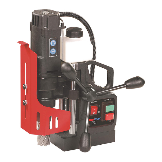
- Page 1 ® Portable Magnetic Drilling Machine OPERATOR’S MANUAL MODEL #SM-D1 Serial # _______________________________ Date of Purchase ______________________ Steelmax Tools LLC 6200 S Troy Circle Suite 110 Centennial, CO 80111 1-87Steelmax www.steelmax.com sales@steelmax.com...
-
Page 2: Table Of Contents
10. MACHINE’S TEST CERTIFICATE ................... - 27 - 11. WARRANTY CARD ........................- 28 - 12. ANNULAR CUTTERS ....................... - 29 - Steelmax Tools LLC Tel · 303.690.9146 Fax · 303.690.9172 6200 S. Troy Circle. Suite 110. Centennial, CO 80111 email ·... -
Page 3: General Information
1. GENERAL INFORMATION Portable drilling machines with electromagnetic bases are fast becoming very universal power tools not only at steel fabricating workshops or steel building sites but also at every factory maintenance workshop, truck manufacture & repair company, military equipment service, onboard ship maintenance shop etc. Full advantages of electromagnetic drilling machines can be achieved only with optimal tooling. -
Page 4: Technical Data
2. TECHNICAL DATA □ 220-240 V AC/ 50/60 Hz Power supply □ 120 V AC/ 50/60 Hz Power required 1000 W Motor power 920 W Tool holder 3/4” Weldon, 19,05 mm/ Max. milling cutter diameter 1-3/8", 35 mm Max. milling/drilling depth 2”... -
Page 5: Standard Equipment
OPERATING INSTRUCTIONS ( BEFORE YOU BEGIN ) Remove all contents from packaging and inspect to ensure no damage was incurred during shipping. Your SM-D1 package should include the following: 3. STANDARD EQUIPMENT The D1 comes in a set which consists of:... - Page 6 and 32 A fuse for 120V. When used on building sites, it must be supplied through a separation transformer made in the second class of protection. Machine can be used outdoors, but is not weatherproof. Do not expose to rain, snow or frost.
-
Page 7: Start Up And Operation
Examples how safety chain should be fastened. Drawing 1. 5. START UP AND OPERATION 5.1 Cutters and optional equipment features. This drilling machine’s spindle has a Weldon Shank type socket 3/4” or 19,05 mm and is specifically designed for use with annular cutters. Drawing 2. - Page 8 Basically annular cutters are designed to make through holes. On occasions when there is a need for an overlapping hole the pilot should not be used. 5.1.1 Installing and uninstalling the annular cutter Annular cutter installation and uninstallation should be carried out when the machine is turned off and the power cord is unplugged! Installing the annular cutter: 1.
- Page 9 5.2 Operating instructions The machine is supplied in a metal box. Check if all parts listed in paragraph 3 are included. Steel elements of the drilling machine are protected for transit and storing with grease film. Before first start up of the machine all grease should be removed.
- Page 10 CAUTION: READ THE WHOLE INSTRUCTIONS MANUAL BEFORE ATTEMPTING TO START UP 5.3 Before you cut Before positioning the machine on the work piece, always make sure that: work piece is made of steel; thickness of work piece is at least 3/8” (10 mm) surface of steel under the magnet is flat wipe, brush or sand down clean surface where you intended to place the drilling machine, so that you remove rust, paint, dirt etc which would reduce adhesive...
- Page 11 Bring the cutter gently into contact with the work piece and slowly start to apply pressure on the cutter. Making a hole with a milling cutter should ideally be done in one pass. It makes the cutter work better and easier to eject the slug after the hole is completed. If you experience slugs getting stuck inside a cutter after hole is complete, try to reduce pressure on the cutter or use a different coolant.
- Page 12 5.6 The overload protection. The drilling machine is equipped with overload protection system. If machine is working close to overload limit it can be switched off, automatically. In this case the operator should turn it on again. 5.7 Installing and uninstalling the cooling system Installing the cooling system: a) Place the machine in the vertical position, b) Raise the drive and the slide up by using the lever,...
-
Page 13: Maintenance And Service
Uninstalling the cooling system: a) Place the machine in the vertical position, b) Raise the drive and the slide up by using the lever, c) Remove the end of the cooling hose (2) on the connection end (4) in the reducer, d) Remove the cooling system. - Page 14 6.1 Replacement of motor brushes The carbon brushes of the D1 drill should be monitored every 100 working hours. Replacement of motor brushes should be carried out when the machine is switched off and with the power cord unplugged! 1. Loosen 4 4x19 screws (1), fastening the motor cover (2). 2.
-
Page 15: Parts List / Exploded Views
7. Parts List / Exploded Views WRT-0440-24-10-00-0 DRILLING MACHINE Steelmax D1 /115V WRT-0440-24-20-00-0 DRILLING MACHINE Steelmax D1 /230V ITEM PART NUMBER VERSION DESCRIPTION STJ-0440-01-00-00-1 2011 FRAME ASSEMBLY RDK-0440-02-00-00-1 1555 GEARBOX ASSEMBLY SLN-0440-03-00-00-3 2012 MOTOR ASSY/120V SLN-0440-03-00-00-5 2013 MOTOR ASSY/230V OSL-0440-04-00-00-0 2486 GUARD ASSY, UKL-0440-05-00-00-1... - Page 16 - 16 - D1 9/2011 Operators Manual for Drilling Machine...
- Page 17 STJ-0440-01-00-00-1 FRAME ASSEMBLY ITEM PART NUMBER VERSION DESCRIPTION KRP-0440-01-01-00-1 1549 MAIN BODY ASSY WLK-0440-01-02-00-0 PINION SHAFT ASSY z14 1.2.1 USZ-000015 SEAL QUAD-RING 20,22x3,53 PAS-0272-01-03-00-0 D-RING STRAP PDS-0378-02-00-00-1 1063 ELECTROMAGNETIC BASE, PDK-000048 SPRING WASHER 6,1 PRS-000019 EXTERNALE RETAINING RING 28z SRB-000113 HEX.
- Page 18 RDK-0440-02-00-00-1 GEARBOX ASSEMBLY ITEM PART NUMBER VERSION DESCRIPTION KRP-0440-02-01-00-1 1551 GEARCASE ASSY WRZ-0272-02-02-00-0 MOTOR SPINDLE ASSEMBLY WLK-0271-02-03-00-1 PINION SHAFT ASSEMBLY KNC-0234-00-10-00-0 COOLANT COUPLING AMT2-H-19 KOL-0271-02-05-00-1 GEAR - 52 PRS-0271-02-06-00-0 DISTANCE RING PRT-0440-02-02-00-1 GUIDE 2.10 LOZ-000072 BEARING BALL 629 SHIELDED 2.11 LOZ-000047 BEARING BALL 6005 2RS - 18 -...
- Page 19 KRP-0440-02-01-00-1 GEARCASE ASSY ITEM PART NUMBER VERSION DESCRIPTION 2.1.1 KRP-0440-02-01-01-2 1550 GEARCASE 2.1.2 LST-0271-02-01-02-1 GEAR RACK 2.1.3 TLJ-000031 SELF-LUBRICATING SLEEVE 18x20x20 2.1.5 LOZ-000053 BEARING 608 2Z 2.1.6 PRS-000070 SEAL 25x37x7 2.1.7 KLK-000044 DOWEL, PIN 5 x 10 MM 2.1.8 KLK-000048 DOWEL, PIN 5 x 18 2.1.9 SRB-000111 HEX.
- Page 20 WRZ-0272-02-02-00-0 MOTOR SPINDLE ASSEMBLY. ITEM PART NUMBER VERSION DESCRIPTION 2.2.1 KRP-0272-02-02-01-0 MOTOR SPINDLE 2.2.2 WYP-0139-00-02-00-1 PLUNGER 2.2.3 SPR-0271-02-02-03-0 SPRING 2.2.4 USZ-0279-02-01-06-0 SEAL 2.2.5 PRS-000009 INTERNAL RETAINING RING 19W 2.2.6 WKR-000059 HEX. SET SCREW M8 x 10 2.2.7 LOZ-000047 BEARING BALL 6005 2RS - 20 - D1 9/2011 Operators Manual for Drilling Machine...
- Page 21 SLN-0440-03-00-00-3 MOTOR ASSY/120V 2012 SLN-0440-03-00-00-5 2013 MOTOR ASSY/230V ITEM PART NUMBER VERSION DESCRIPTION OBD-0272-03-01-01-1 FIELD FRAME OSL-0271-03-01-02-0 GUARD PWD-0440-03-01-00-0 MOTOR CORD STN-000002 FIELD /120V C-34116/1 STN-000004 FIELD /230V C-34116 WKR-000241 SCREW FOR PLASTIC 4x19 KNC-000006 CONNECTOR 48-201-06 PKR-0272-03-02-01-2 GEARBOX COVER PRS-0271-03-02-02-1 GEARBOX COVER RING WRN-000016...
- Page 22 UKL-0440-05-00-00-1 COOLANT BOTTLE ASSY ITEM PART NUMBER VERSION DESCRIPTION BTL-0440-05-01-00-4 BOTTLE, NKR-000116 ZWR-000010 COOLANT VALVE PDK-0232-00-01-00-0 SEAL WASHER WAZ-000004 PLASTIC HOSE 4MM 0,16m - 22 - D1 9/2011 Operators Manual for Drilling Machine...
- Page 23 PNL-0272-04-00-00-4 2015 CONTROL PANEL ASSEMBLY /120V, PNL-0272-04-00-00-5 2014 CONTROL PANEL ASSEMBLY /230V, ITEM PART NUMBER VERSION DESCRIPTION MSK-0300-04-01-00-1 2018 PANEL PLATE ASSY 6.1.1* NKL-0440-15-08-01-0 LABEL PANEL PLATE STR-0257-04-10-00-2 ELECTRONIC CONTROLLER SW-31M /120V, STR-0257-04-10-00-3 ELECTRONIC CONTROLLER SW-31M /230V, WLC-000005 SWITCH START-STOP /115V, WLC-000007 SWITCH START-STOP /230V, PNK-000013...
-
Page 24: Electrical Diagrams
8. ELECTRICAL DIAGRAMS - 24 - D1 9/2011 Operators Manual for Drilling Machine... - Page 25 - 25 - D1 9/2011 Operators Manual for Drilling Machine...
-
Page 26: Declaration Of Conformity
EN 50144-1, EN 55014 and satisfies safety regulations of guidelines: 2004/108/EC, 2006/95/EC, 2006/42/EC Bialystok, 2010-04-19 ___________________________ Prezes Steelmax Tools LLC 6200 S Troy Circle Suite 110 Centennial, CO 80111 1-87Steelmax www.steelmax.com sales@steelmax.com... -
Page 27: Machine's Test Certificate
Resistance of the protective circuit [Ω] The above-mentioned product meets the requirements of safe usage as prescribed in standard IEC-745 Name of tester ____________________ Quality Control ____________________ Steelmax Tools LLC 6200 S Troy Circle Suite 110 Centennial, CO 80111 1-87Steelmax www.steelmax.com sales@steelmax.com... -
Page 28: Warranty Card
11. WARRANTY CARD WARRANTY CARD No..... Steelmax Tools LLC in the name of Manufacturer warrants the Drilling Machine to be free of defects in material and workmanship under normal use for a period of 12 months from date of sold. - Page 29 3/4” SHANK M2AL ANNULAR CUTTERS 1" D.O.C. 2" D.O.C. M2AL Cutter DECIMAL Diameter EQUIVALENT PART# PART# 7/16” 0.4375 SM-AC-0438-1 SM-AC-0438-2 1/2” 0.5000 SM-AC-0500-1 SM-AC-0500-2 9/16” 0.5625 SM-AC-0563-1 SM-AC-0563-2 5/8” 0.6250 SM-AC-0625-1 SM-AC-0625-2 11/16” 0.6875 SM-AC-0688-1 SM-AC-0688-2 3/4” 0.7500 SM-AC-0750-1 SM-AC-0750-2 13/16”...
Need help?
Do you have a question about the SM-D1 and is the answer not in the manual?
Questions and answers