Table of Contents
Advertisement
Quick Links
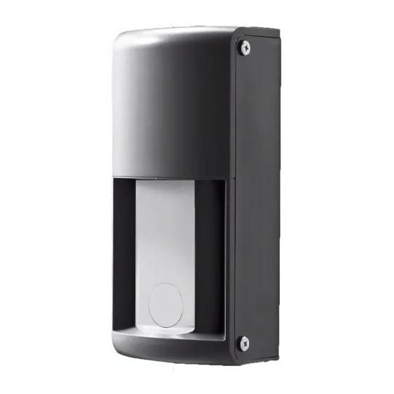
Vehicle Detection Sensor for Vehicle Counting
OVS-01CC
Features
●
dual detection technologies : Doppler shift and
●
●
(automatically activates based on the outside air
Not affected by underground obstructions, this
●
product is installed above ground.
●
Installation Instructions
Table of Contents
1
2
3
3-1
3-2
3-3
3-4
4
4-1
4-2
4-3
4-4
4-5
5
5-1
6
7
7-1
Specifications
7-2
7-3
-1-
No.59-2654-0 170918
2
3
4
4
5
7
8
10
10
13
14
15
17
18
18
19
20
20
21
21
Advertisement
Table of Contents

Related Manuals for Optex OVS-01CC


Summary of Contents for Optex OVS-01CC
-
Page 1: Table Of Contents
No.59-2654-0 170918 Installation Instructions Vehicle Detection Sensor for Vehicle Counting OVS-01CC Table of Contents Safety Precautions Features Component Name Before Using the Product The sensor can count moving vehicles by using ● Detection Principle and Basic Operation of the Sensor... -
Page 2: Safety Precautions
Safety Precautions This product is a vehicle detection sensor designed for a car counting , installed beside a drive way. Do not use the product for other purposes. For Safe Use About the Marks The description given here is for correct usage of the product without causing damage to you, other personnel as well as damage to properties.The marks and their meanings are as follows: Please read the text after understanding the contents well. -
Page 3: The Sensor Can Count Moving Vehicles By Using
Component Name Sensor Unit Operation Unit Front Cover Sensor Unit Base ■ Operation Unit OVS-01CC Sensitivity Value Button VALUE Value Indicator Standby Maximum Range (m) Microwave Maximum Area Check Operation Indicator Detection Range Button Calibration Output1 Output2 Calibration Area Check Area Check Button N.O. -
Page 4: Reduced (Patent Pending)
Before Using the Product Detection Principle and Basic Operation of the Sensor ● Detection Principle This sensor uses reflection of a microwave signal to detect a vehicle. ● (The higher the reflection, the easier the detection becomes.) The microwave sensor uses FMCW technology, it can detect a vehicle in the lot. ●... -
Page 5: Sensor Installation Recommendations
Sensor Installation Recommendations Install the pole for the sensor in the following layout configuration. The sensor will not work correctly unless its installation direction and height are correct. Installation height: 500mm(19.69in.) from the ground to the bottom of the sensor Installation angle: 90 degrees to the vehicle direction of travel. -
Page 6: Reduced Installation Time As Access Road For
If the pole is installed on a slope, install the sensor higher or lower in order to adjust NOTE ● the height of the set detection range to 500mm(19.69in.) from the ground. It may reduce the detection capability compared to the normal installation. 500mm(19.69in.) Height of the set detection range Ground... -
Page 7: Vehicle Is Not Closed, As No Civil Engineering
Sensor Detection Recommendations A vehicle is detected when it approaches the sensor at speeds of 2 to 60kph (1.24 to 37.28mph). ● The following cases may occur due to the sensor's characteristics. NOTE The sensor may not work properly if it is installed in a location that does not meet the ●... -
Page 8: Installation Workflow
Remove the front cover and sensor unit, and attach the sensor and connect the wire. [3] Setting Verification and Modification (if needed): Go to P.13 OVS-01CC Check the settings, and if necessary, change them based on the installation environment and applications. - Page 9 [5] Detection Area Check: Go to P.15 Verify the detection area. If needed, change the installation angle of the unit and/or sensing distance setting. * Once the installation condition such as the angle is modified, perform the calibration again. OVS-01CC Sensitivity VALUE Standby...
-
Page 10: Installation Steps (Basic)
Installation Steps (Basic) Installation of the Unit ■Required Tools■ ●Precision screwdriver, Phillips #1 ●Screwdriver, Phillips #2 [1] Drill pilot holes into the poles and attach the sensor. Mounting Pitch 32±1 (1.26±0.04) [Unit : mm(inch)] [2] Run the wire through the poles. [3] Fix the poles so that the sensor faces the angle shown below. - Page 11 [4] Loosen the retaining screws on the bottom of the front cover and remove the front cover. * Do not loosen the screw completely. The screw may fall out. If losing the screw, use a M3 x 10 philips screw. [5] Detach the sensor unit.
- Page 12 [8] Attach the sensor unit to the base. Press the excess wire back into to the pole while attaching the unit. [9] Perform the steps in P.13 through 16 "4-2 Setting Verification and Adjustment", "4-3 Calibration", and "4-4 Detection Area Check". [10] Put the front cover on the top of the base first, and attach it while spreading it open and pushing down the front cover.
-
Page 13: Setting Verification And Adjustment
Setting Verification and Adjustment This section describes how to verify the basic settings. Use the OVS-01CC buttons to change the settings if needed. Sensitivity VALUE Standby Maximum Range (m) Basic Setting Items Area Check Detection Calibration Output1 Output2 Calibration Area Check N.O. -
Page 14: Calibration
Calibration ●Calibration function This function records (memorizes) the background of the detection area without any pedestrians or vehicle present. This process makes the sensor detection capability higher and provides stable detection. If any noticeable changes occur around the detection area (such as construction of a wall or fence), you must perform the calibration again. -
Page 15: Detection Area Check
Detection Area Check ● Detection Area Check Function This function allows you to visually check the detection area of the microwave signal using the operation indicator. It is possible to verify the correct angle and size of the detection area. *This detection area check must be performed after calibration. - Page 16 [3] Stand at the edge of the vehicle lane (see Figure [B]), walk along the border and verify that the operation indicator keeps blinking green (not detecting). If the operation indicator changes to blinking red (detecting), adjust the sensor angle and/or range setting again.
-
Page 17: Other Functions
Other Functions ● Automatic Indicator OFF If a button is not pressed for 30 minutes, the operation indicator dims and other indicators turn off. Pressing any button turns the indicators back on. Standby Area Check Operation Indicator Detection Calibration Calibration Area Check ●... -
Page 18: Advanced Installation
Keep pressing the button until the desired setting is reached. The sensitivity setting switches from 1 to 2, 3, 4, 5, and then returns to 1, 2, and so on. (e.g.: If the sensitivity is 3, three indicators are turned on). value Press the button to select the sensitivity. OVS-01CC Sensitivity VALUE Standby Maximum Range (m) -
Page 19: Troubleshooting
Troubleshooting Symptom Cause Action Operation indicator does not turn ON. Power may not be supplied. Connect power supply of 12-24VDC. The supply voltage may not be correct. Check power supply voltage 12-24VDC. The power supply polarity is wrong Check power supply polarity. (wrong polarity does not cause a failure but the product does not work). -
Page 20: Specifications
Specifications Specifications Model OVS-01CC Detection Method Combination of microwave Doppler shift and FMCW technologies Sensor Frequency 24GHz Response 300msec Supply Voltage 12 - 24VDC Heater enabled: Up to 190mA, Heater disabled : Up to 70mA (at 24V) Power Consumption Relay output DC30V, 0.3A (N.O. / N.C. switchable) -
Page 21: Detection Area Diagram
Detection Area Diagram [Unit: m] 1m=3.28ft. Side View Top View 8m setteing 8m setting Installation height 0.5m, Sensitivity: 3, Detection area check mode * Under the normal operation mode, the detection area by an actual vehicle may be smaller. Dimensions [Unit:mm(inch)] Cable Hole 14(0.55) Mounting Pitch 32(1.26) - Page 22 Hereby, OPTEX declares that the radio equipment type OVS-01CC isin compliance with RED 2014/53/EU. The full text of the EU DoC is available at the following internet address: www.optex.net EU contact information Manufacturer: OPTEX CO., LTD. 5-8-12 Ogoto, Otsu, Shiga, 520-0101 JAPAN Authorised representative in Europe: OPTEX (EUROPE) LTD.
- Page 23 -23-...
- Page 24 FAX:+81-77-579-8190 URL:http://www.optex.co.jp/e/ OPTEX INC. (USA) OPTEX SECURITY Sp.zo.o. (POLAND) TEL:800-877-6656 (Toll free) TEL:+48-22-598-06-55 FAX:+1-310-898-1098 URL:http://www.optex.com.pl/ URL:http://www.optexamerica.com/ OPTEX KOREA CO., LTD. (KOREA) OPTEX (EUROPE)LTD. (UK) TEL:+82-2-719-5971 TEL:+44-1628-631000 URL:http://www.optexkorea.com/ URL:http://www.optex-europe.com/ OPTEX (DONGGUAN) CO., LTD. OPTEX SECURITY SAS (FRANCE) SHANGHAI OFFICE (CHINA) TEL:+33-437-55-50-50 TEL:+86-21-34600673 URL:http://www.optex-security.com/...
Need help?
Do you have a question about the OVS-01CC and is the answer not in the manual?
Questions and answers