Advertisement
OVS-01CC Quick Reference Guide
1. Install the pole for the sensor in the following layout configuration.
Installation height: 500mm(19.69in.) from the ground to the bottom of the sensor
Installation angle: 90 degrees to the vehicle direction of travel.
90°
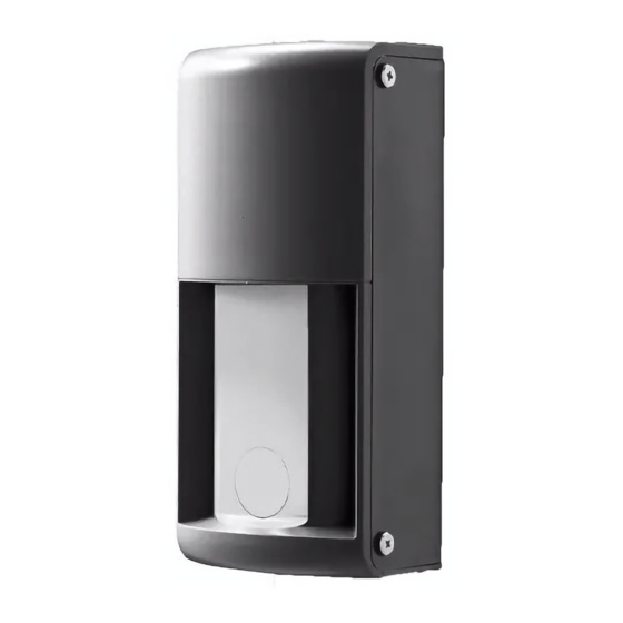
Sensor
Two way traffic lane : Install the sensor on the the lane of traffic you wish to monitor.
The sensor cannot detect a vehicle in the opposite lane.
Road not to
be detected
Road to
be detected
2. Install the sensor, wire it and apply power.
[1] Make holes to mount the sensor.
[2] Run a cable thru the post or pole.
Mounting
Pitch 32±1
(1.26±0.04)
[Unit : mm(inch)]
Vehicle Path
Road not to
be detected
Road to
be detected
[3] Loosen the retaining screws on the bottom
of the front cover and remove the front
cover, detach the sensor unit.
Hold here and
pull forward
[4] Fix the base using 4 screws.
[5] Connect wires.
Power
[6] Attach the sensor body to the base
and adjust the sensor angle.
4. Perform calibration in order to memorize the
background of the detection area. Ensure no
pedestrians or vehicles are present.
1. Press the Calibration button.
Standby
Area Check
2. Operation indicator blinks in blue.
Detection
Calibration
3. Step away from sensor and
Calibration Area Check
outside detection area.
4. Green LED lights when done
correctly.
6. Put the front cover on the top of the base first, and attach it
while spreading it open and pushing down the front cover.
Output1
Output2
Applicable Wire
Single conductor: 0.5-1.2mm (equivalent to CPEV)
Stranded wire: 0.3-2.0sq
Non-Voltage Relay Output N.O./N.C. Switchable
30VDC 0.3A or less (resistance load)
Non-Voltage Relay Output N.O./N.C. Switchable
30VDC 0.3A or less (resistance load)
Power Supply 12-24VDC
3. Set the Microwave maximum range.
Recommended to set the range 1m(3.28ft.) shorter than the
actual width of the road.
Maximum Range (m)
1
2
Maximum Range Botton
5
6
Output1
Output2
N.O.
N.C.
5. System operation check.
Check the entire coverage area by using actual vehicle.
Sensor
7. Tighten the front cover retaining screw.
3
4
7
8
Calibration
N.O.
N.C.
Left side of the lane
Center of the lane
Right side of the lane
Advertisement
Table of Contents

Related Manuals for Optex OVS-01CC


Summary of Contents for Optex OVS-01CC
- Page 1 OVS-01CC Quick Reference Guide [4] Fix the base using 4 screws. [5] Connect wires. Power Output1 Output2 Applicable Wire Single conductor: 0.5-1.2mm (equivalent to CPEV) 1. Install the pole for the sensor in the following layout configuration. Stranded wire: 0.3-2.0sq Installation height: 500mm(19.69in.) from the ground to the bottom of the sensor...
Need help?
Do you have a question about the OVS-01CC and is the answer not in the manual?
Questions and answers