
Related Manuals for mikroElektronika mikromedia for STM32


Summary of Contents for mikroElektronika mikromedia for STM32
- Page 1 mikromedia ™ for STM32 ® Compact multimedia development system rich with on-board peripherals for all-round development on STM32F207VGT6 STM32F407VGT6 devices...
- Page 2 TO OUR VALUED CUSTOMERS I want to express my thanks to you for being interested in our products and for having confidence in MikroElektronika. The primary aim of our company is to design and produce high quality electronic products and to constantly improve the performance thereof in order to better suit your needs.
-
Page 3: Table Of Contents
Table of Contents Introduction to mikromedia for STM32® Programming with mikroProg™ programmer Package Contains mikroProg Suite™ for ARM® Software Key Features Programming with ST-LINK V2 programmer System Specification 4. Reset buttons 1. Power supply 5. Oscillators USB power supply 6. MicroSD Card Slot Battery power supply 7. -
Page 4: Introduction To Mikromedia For Stm32
Introduction to mikromedia for STM32® mikromedia for STM32® is a compact development system with lots of on-board peripherals which allow development of devices with multimedia contents. The central part of the system is a 32-bit STM32F207VGT6 STM32F407VGT6 microcontroller. The mikromedia for STM32® features integrated... -
Page 5: Package Contains
Package Contains 20122011 www.mikroe.com Copyright ©2011 Mikroelektronika. All rights reserved. Mikroelektronika, Mikroelektronika logo and other Mikroelektronika trademarks are the property of Mikroelektronika. All other tradmarks are the property of their respective owners. Unauthorised copying, hiring, renting, public performance and broadcasting of this DVD prohibited. -
Page 6: Key Features
Key Features Connection Pads TFT 320x240 display USB MINI-B connector Charge indication LED LI-Polymer battery connector 3.5mm headphone connector Power supply regulator Crystal oscillator VS1053 Stereo mp3 coder/decoder RESET button STM32F207VGT6 or STM32F407VGT6 microcontroller Accelerometer Serial Flash memory microSD Card Slot Power indication LED JTAG/SWD programmer connector Page 6... -
Page 7: System Specification
System Specification power supply Via USB cable (5V DC) power consumption 46.5 mA with erased MCU (when on-board modules are inactive) board dimensions 81.2 x 60.5 mm (3.19 x 2.38 inch) weight ~45 g (0.10 lbs) Page 7... -
Page 8: Power Supply
1. Power supply USB power supply You can apply power supply to the board using MINI-B USB cable provided with the board. On-board voltage regulators provide the appropriate voltage levels to each component on the board. Power LED (GREEN) will indicate the presence of power supply. - Page 9 VCC-SYS VCC-USB AVCC VCC-3.3 PMEG3010ER FERRITE VCC-SYS VBUS DMP2160UW HDR1 HDR2 2.2uF 100nF 10nF VCC-BAT USB MINIB BATT CONN VCC-1.8 VCC-3.3 VCC-BAT VCC-1.8 VREF-1.8 VCC-1.8 10uF 2.2uF Vout VSENSE 120K 2.2uF 100nF AP7331-ADJ VCC-3.3 VCC-3.3 12K1 VCC-3.3 Figure 1-3: Power supply schematics M1X26 M1X26 VCC-3.3...
-
Page 10: Key Microcontrollers Features
2. Key microcontrollers features The mikromedia for STM32® M3 development system comes with the STM32F207VGT6 microcontroller. This high- 32-bit performance microcontroller with its integrated modules and in combination with other on-board modules is ideal for multimedia applications. STM32F207VGT6 - 1.25 DMIPS/MHz, 32-bit Cortex -M3 Core;... -
Page 11: Stm32F407Vgt6
The mikromedia for STM32® M4 development system comes with the STM32F407VGT6 microcontroller, which can deliver even more processing power. With up to 168MHz operation, 32-bit this microcontroller with other on-board modules is a perfect choice for performance-demanding applications. STM32F407VGT6 - 1.25 DMIPS/MHz, 32-bit Cortex -M4 Core;... -
Page 12: Programming The Microcontroller
3. Programming the microcontroller Figure 3-1: STM32F207VGT6 Microcontroller Figure 3-2: STM32F407VGT6 Microcontroller Page 12... - Page 13 Via USB mikroBootloader Using external mikroProg™ programmer programmer The mikromedia for STM32® development system can be programmed in three different ways. Using bootloader which is pre-programmed into device by default or via external programmers ( mikroProg™ or ST-LINK V2™) .
-
Page 14: Programming With Mikrobootloader
Programming with mikroBootloader step 1 – Connecting mikromedia You can program the microcontroller with bootloader which is pre-programmed into the device by default. To transfer .HEX file from a PC to MCU you need bootloader software (mikroBootloader USB HID) which can be downloaded from: http://www.mikroe.com/eng/products/view/853/ mikromedia-for-stm32/ After software is downloaded unzip it to desired location and... -
Page 15: Step 2 - Browsing For .Hex File
step 2 – Browsing for .HEX file step 3 – Selecting .HEX file Figure 3-4: Browse for HEX Figure 3-5: Selecting HEX Click the ”Browse for HEX” button and from a Select .HEX file using open dialog window. pop-up window (Figure 3.5) choose the .HEX file ”Open”... -
Page 16: Step 4 - Uploading .Hex File
step 4 – Uploading .HEX file Figure 3-6: Begin uploading Figure 3-7: Progress bar To start .HEX file bootloading click the You can monitor .HEX file uploading via progress bar ”Begin uploading” button. Page 16... -
Page 17: Step 5 - Finish Upload
step 5 – Finish upload Figure 3-8: Restarting MCU Figure 3-9: mikroBootloader ready for next job ”OK” Click the button after uploading is finished and wait for 5 seconds. Board will automatically reset and your new program will execute. Page 17... -
Page 18: Programming With Mikroprog™ Programmer
Programming with mikroProg programmer ™ mikroProg™ for STM32® programmer mikroProg Suite™ for ARM® The microcontroller can be programmed with external software. The mikroProg™ programmer is connected to the development system via the CN5 (JTAG) connector. You can choose between two ways to program microcontrollers , Figure 3-14: JTAG interface... -
Page 19: Mikroprog Suite™ For Arm® Software
DVD://download/eng/software/development-tools/arm/mikroprog/ mikroprog_suite_for_arm_v110.zip Copyright ©2011 Mikroelektronika. All rights reserved. Mikroelektronika, Mikroelektronika logo and other After downloading, extract the package and double click the executable Mikroelektronika trademarks are the property of Mikroelektronika. All other tradmarks are the property of their respective owners. -
Page 20: Programming With St-Link V2 Programmer
Programming with ST-LINK V2 programmer ST-LINK V2 programmer The microcontroller can be also programmed with mikroProg Suite™ for ARM® software, Figure 3-11 . This programmer connects mikroProg to ST-LINK V2 adapter. with mikromedia board via Figure 3-12: In order to adjust the ST-LINK™ V2 programmer mikroProg™... - Page 21 VCC-3.3 2.2uF VCC-3.3 TMS/ SWDIO TCK/ SWCLK AVCC 100K TRST RESET# JTAG (SWD) VREF-1.8 PB12 PB13 PB14 PA0-WKUP VCC-3.3 PB15 VDDA VREF+ GNDA VCC-3.3 VCC-3.3 VCC-3.3 PD10 PD11 PD12 PD13 10uF 100nF 100nF PD14 RESET# STM32F207VGT6 PD15 NRST OSC_OUT STM32F407VGT6 OSC_IN VCC-3.3 VCC-3.3 VCC-3.3...
-
Page 22: Reset Buttons
4. Reset Buttons Board is equipped with two reset buttons. First is located at the back side of the board (Figure 4-1), and second one is at the top of the front side (Figure 4-2). If you want to reset the circuit, press either of two buttons. It will generate low voltage level on microcontroller reset pin (input). - Page 23 VCC-3.3 2.2uF VCC-3.3 HDR2 AVCC 100K 100nF VREF-1.8 PB12 PB13 PB14 PA0-WKUP VCC-3.3 PB15 VDDA VREF+ GNDA PD10 PD11 PD12 PD13 PD14 STM32F207VGT6 PD15 NRST OSC_OUT R7 100 STM32F407VGT6 OSC_IN 22pF VCC-3.3 OSC32_OUT PC15/OSC32_OUT OSC32_IN 32.768KHz PC14/OSC32_IN M1X26 PA10 PC13/TAMPER_RTC PA11 VBAT 22pF...
-
Page 24: Oscillators
5. Oscillators STM32F207VGT6 STM32F407VGT6 microcontrollers are equipped with internal 16MHz RC oscillator that provides stable clock signal. Since the chips have an integrated PLL, this base frequency is suitable for further clock multiplication. Board also contains 32.768kHz Crystal oscillator (X1) RTCC which provides external clock for internal module. -
Page 25: Microsd Card Slot
6. MicroSD Card Slot microSD card slot Board contains for using microSD cards in your projects. It enables you to store large amounts of data externally, thus saving microcontroller memory. MicroSD cards use Serial Peripheral Interface (SPI) for communication with the microcontroller. 2.2uF VCC-3.3 VCC-3.3 VCC-3.3 VCC-3.3 VCC-3.3... -
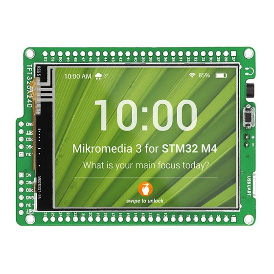
Page 26: Touch Screen
7. Touch Screen TFT 320x240 display resistive The development system features a covered with a touch panel. Together they form a functional unit called a touch screen. It enables data to be entered and displayed at the same time. The TFT display is capable of 262.144 diffe rent colors. - Page 27 VCC-SYS VCC-3.3 VCC-3.3 TFT1 2.2uF VCC-3.3 LED-K LED-A1 LED-A2 AVCC 100K LED-A3 BC846 LED-A4 LCD-BLED BC846 LCD-RST RESET VSYNC VREF-1.8 PB12 HSYNC VCC-3.3 PB13 DOTCLK BC846 PB14 PA0-WKUP ENABLE VCC-3.3 T-D7 PB15 VDDA DB17 10uF T-D6 VREF+ DB16 T-D5 GNDA DB15 T-D4 PD10...
-
Page 28: Audio Module
8. Audio Module Figure 8-1: On-board VS1053 MP3 codec Figure 8-2: The mikromedia for STM32® features stereo audio codec VS1053. This module Inserting 3.5mm enables audio reproduction by using stereo headphones connected to the headphones jack system via a 3.5mm connector CN2. - Page 29 2.2uF VCC-3.3 VCC-3.3 VCC-1.8 VCC-1.8 VCC-1.8 VCC-1.8 VCC-3.3 VCC-3.3 VCC-3.3 VCC-3.3 VCC-3.3 AVCC 100K MP3-CS# 100nF 100nF 100nF 100nF 100nF 100nF 100nF 100nF 100nF MP3-RST# decoupling VREF-1.8 capacitors PB12 PB13 PB14 PA0-WKUP VCC-3.3 PB15 VDDA VREF+ GNDA PD10 PD11 PD12 PD13 PD14 STM32F207VGT6...
-
Page 30: Usb Connection
9. USB connection STM32F207VGT6 STM32F407VGT6 microcontrollers have integrated module, which enables you to implement USB communication functionality to your mikromedia board. Connection with target USB host is done over MINI-B USB connector which is positioned next to the battery connector. Figure 9-1: Connecting USB cable to programming... - Page 31 2.2uF VCC-3.3 AVCC 100K VCC-3.3 VCC-3.3 VCC-3.3 VREF-1.8 PB12 PB13 PB14 PA0-WKUP VCC-3.3 10uF 100nF 100nF PB15 VDDA VREF+ GNDA PD10 PD11 VCC-3.3 VCC-3.3 VCC-3.3 PD12 PD13 PD14 STM32F207VGT6 PD15 NRST 100nF 100nF 100nF OSC_OUT STM32F407VGT6 OSC_IN PC15/OSC32_OUT decoupling USB-DET PC14/OSC32_IN capacitors PA10...
-
Page 32: Accelerometer
10. Accelerometer ADXL345 On board accelerometer is used to measure acceleration in three axis: x, y and z. The acceleromer’s function is defined by the user in the program loaded into the microcontroller. Communication between the accelerometer and the microcontroller is I 2 C performed via the interface. -
Page 33: Flash Memory
11. Flash Memory 2.2uF VCC-3.3 AVCC 100K VREF-1.8 PB12 PB13 PB14 PA0-WKUP VCC-3.3 PB15 VDDA VREF+ GNDA PD10 PD11 Figure 11-1: PD12 PD13 PD14 Flash memory module STM32F207VGT6 PD15 NRST VCC-3.3 VCC-3.3 VCC-3.3 VCC-3.3 VCC-3.3 VCC-3.3 OSC_OUT STM32F407VGT6 OSC_IN PC15/OSC32_OUT 10uF 100nF 100nF... -
Page 34: Pads
12. Pads 2.2uF VCC-3.3 VCC-SYS AVCC 100K HDR2 HDR1 PB12 VREF-1.8 PB12 PA10 SCK2-PB13 PB13 PD14 MISO2-PB14 PB14 PA0-WKUP VCC-3.3 MOSI2-PB15 PB15 VDDA VREF+ GNDA PD10 PD10 PD11 PD11 PD12 PD12 PD10 PD13 SCL2-PB10 PD13 PD11 PD14 SDA2-PB11 PD14 PD12 PB12 STM32F207VGT6 PD15... -
Page 35: Pinout
13. Pinout System power supply VSYS Reset pin Reference Ground Reference Ground left ch. audio out right ch. Analog Lines PWM lines PA10 PD14 Interrupt Lines Digital I/O lines PB10 PD10 PB11 PD11 PB12 PD12 Digital I/O lines PB13 PD13 PB14 PE13 PB15... -
Page 36: Dimensions
14. Dimensions 81.15 mm (3195 mils) 73.66 mm (2900 mils) 63.5 mm (2500 mils) 2.54 mm 2.67 mm (100 mils) (105 mils) Page 36... -
Page 37: Mikromedia Accessories
15. Mikromedia accessories We have prepared a set of extension boards pin-compatible with your mikromedia, which enable you to easily expand your board basic functionality. call them mikromedia shields. But we also offer other accessories, such as Li-polymer battery, stacking headers, wire jumpers and more. -
Page 38: What's Next
What’s next? You have now completed the journey through each and every feature of mikromedia for STM32® board. You got to know it’s modules and organization. Now you are ready to start using your new board. We are suggesting several steps which are probably the best way to begin. We invite you to join the users of mikromedia™... - Page 39 No part of this manual, including product and software described herein, may be reproduced, stored in a retrieval system, translated or transmitted in any form or by any means, without the prior written permission of MikroElektronika. The manual PDF edition can be printed for private or local use, but not for distribution.
- Page 40 If you are experiencing some problems with any of our products or just need additional information, please place your ticket at www.mikroe.com/esupport If you have any questions, comments or business proposals, mikromedia for STM32 ® M3/M4 Manual ver. 1.00 do not hesitate to contact us at office@mikroe.com...
Need help?
Do you have a question about the mikromedia for STM32 and is the answer not in the manual?
Questions and answers