
Subscribe to Our Youtube Channel
Related Manuals for mikroElektronika CLICKER PIC32MX


Summary of Contents for mikroElektronika CLICKER PIC32MX
- Page 1 A compact starter kit with your favorite microcontroller and a socket for click add-on ™ boards. New ideas are just a click away.
- Page 2 TO OUR VALUED CUSTOMERS I want to express my thanks to you for being interested in our products and for having confidence in MikroElektronika. The primary aim of our company is to design and produce high quality electronic products and to constantly improve the performance thereof in order to better suit your needs.
-
Page 3: Table Of Contents
Table of Contents 1. What is PIC32MX clicker? step 4 – Uploading .HEX file 2. Power supply step 5 – Finish upload 3. PIC32MX534F064H microcontroller Programming with mikroProg Programmer ™ Key microcontroller features 5. mikroProg Suite for PIC Software ™ ®... -
Page 4: What Is Pic32Mx Clicker
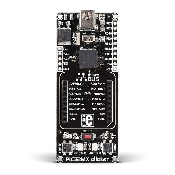
1. What is PIC32MX clicker? USB Mini-B connector 3.3V Voltage regulator mikroProg Programmer connector ™ PIC32MX534F064H microcontroller Crystal oscillators (8MHz and 32kHz) Connection pads mikroBUS socket ™ RESET button Power indication LED Additional buttons Figure 1-1: PIC32MX clicker Additional LEDs PIC32MX clicker is an amazingly compact starter development kit which brings innovative mikroBUS host socket to your favorite ™... - Page 5 3.3V VOLTAGE REGULATOR VCC-3.3 VCC-3.3 VCC-3.3 VCC-3.3 REG1 VCC-3.3 VCC-5V 100nF 100nF 100nF 100nF 100nF 2.2uF Vout LD29080DT33 10uF 10uF VCC-5V FERRITE USB-DET VBUS USB-D_N USB-D_P VCC-3.3 USB-ID RD1/LED2 10uF 100nF USB MINIB RD4/LED1 22pF SOSCO VCC-3.3 SOSCI RD0/PWM RG6/SCK RD11/INT RD11 RG7/MISO...
-
Page 6: Power Supply
2. Power supply When the board is powered up the power indication LED will be automatically turned on. The USB connection can provide up to 500mA of current which is more than enough for the operation of all on-board and additional modules. Figure 2-1: connecting USB power supply through CN1 connector... - Page 7 3.3V VOLTAGE REGULATOR VCC-3.3 VCC-3.3 VCC-5V VCC-3.3 REG1 FERRITE VCC-5V VBUS Vout LD29080DT33 10uF 10uF 100nF USB MINIB Figure 2-2: Power supply schematic Page 7...
-
Page 8: Pic32Mx534F064H Microcontroller
3. PIC32MX534F064H microcontroller The PIC32MX clicker development tool comes with the PIC32MX534F064H microcontroller. This 32-bit MIPS M4K Core high performance microcontroller is rich with on-chip peripherals and features 64KB of Flash and 16KB RAM. It has integrated full speed USB 2.0. support. Key microcontroller features - 80MHz/105DMIPS, 32-bit MIPS M4K Core;... -
Page 9: Programming The Microcontroller
4. Programming the microcontroller Figure 4-1: PIC32MX534F064H microcontroller The microcontroller can be programmed in two ways: Using USB HID mikroBootloader, Using external mikroProg for PIC , dsPIC , PIC32 programmer. ™ ® ® ® Page 9... -
Page 10: Programming With Mikrobootloader
Software File folder mikroBootloader USB HID.exe Figure 4-2: USB HID mikroBootloader window Bootloader tool for mikroElektron... mikroElektronika To start, connect the USB cable, or if already connected Firmware File folder press the Reset button on your PIC32MX clicker. Click the... -
Page 11: Step 2 - Browsing For .Hex File
step 2 – Browsing for .HEX file step 3 – Selecting .HEX file Figure 4-3: Browse for HEX Figure 4-4: Selecting HEX Click the Browse for HEX button and from a Select .HEX file using open dialog window. pop-up window (Figure 3.4) choose the .HEX file which will be uploaded to MCU memory. -
Page 12: Step 4 - Uploading .Hex File
step 4 – Uploading .HEX file Figure 4-5: Begin uploading Figure 4-6: Progress bar To start .HEX file bootloading click the Progress bar enables you to monitor .HEX file Begin uploading button. uploading. Page 12... -
Page 13: Step 5 - Finish Upload
step 5 – Finish upload Figure 4-8: mikroBootloader ready for next job Figure 4-7: Restarting MCU Click OK button after the uploading process is finished. Press Reset button on PIC32MX clicker board and wait for 5 seconds. Your program will run automatically. Page 13... -
Page 14: Programming With Mikroprog ™ Programmer
Programming with mikroProg programmer ™ Figure 4-9: mikroProg connector ™ The microcontroller can be programmed with external mikroProg for PIC , dsPIC and PIC32 programmer and mikroProg Suite ™ ® ® ® ™ for PIC software. The external programmer is connected to the development system via 1x5 mikroProg connector, Figure 4-9. - Page 15 VCC-3.3 VCC-3.3 10uF 100nF 100nF 100nF 100nF 100nF 2.2uF 22pF SOSCO SOSCI RD11 22pF RD10 MCLR# 22pF MCLR PIC32MX534F064H OSC2 OSC1 D+/RG2 22pF D-/RG3 VUSB VBUS USBID/RF3 VCC-3.3 RB6/PGC RB7/PGD MCLR# mPROG Figure 4-10: mikroProg connection schematic ™ NOTE Make sure to use only the front row of mikroProg’s IDC10 connector (side with a knob and incision) when connecting it to 1x5 header on your PIC32MX clicker board.
-
Page 16: Mikroprog Suite ™ For Pic ® Software
5. mikroProg Suite for PIC Software ™ ® The mikroProg programmer requires ™ special programming software called mikroProg Suite for PIC . It can be ™ ® used for programming all Microchip ® microcontroller families, including PIC10 ® PIC12 , PIC16 , PIC18 , dsPIC30/33 ®... - Page 17 Software Installation Wizard Start Installation Accept EULA and continue Install for all users Choose destination folder Installation in progress Finish installation Page 17...
-
Page 18: Buttons And Leds
6. Buttons and LEDs Figure 6-1: Two buttons, two LEDs and a reset button The board also contains reset button and a pair of buttons and LEDs. Each of these additional peripheral are located in the bottom area of the board. Reset button is used to manually reset the microcontroller. Pressing the reset button will generate low voltage level on microcontroller reset pin. - Page 19 VCC-3.3 VCC-3.3 MCLR# 10uF 100nF 22pF SOSCO SOSCI RD1/LED2 RD11 22pF RD10 MCLR# 22pF MCLR RD4/LED1 PIC32MX534F064H OSC2 OSC1 RB4/T1 D+/RG2 22pF D-/RG3 VCC-3.3 VCC-3.3 VUSB VBUS PB0/T2 USBID/RF3 VCC-3.3 100nF 100nF 100nF 100nF 100nF 2.2uF Figure 6-2: Other modules connection schematic Page 19...
-
Page 20: Click ™ Boards Are Plug And Play
7. click boards are plug and play! ™ Up to now, MikroElektronika has released more than 100 mikroBUS compatible click ™ ™ boards. On the average, one click board is released per ™ week. It is our intention to provide you with as many... - Page 21 RFid click Relay click 8x8 click FM click Bluetooth2 click Thunder click ™ ™ ™ ™ ™ ™ USB SPI click ™ BarGraph click 7seg click THERMO click Gyro click EEPROM click LightHz click Pressure click ™ ™ ™ ™ ™...
-
Page 22: Pinout
8. Pinout In addition to the mikroBUS socket, the PIC32MX clicker ™ has a row of 9 pins with Analog, Interrupt, I2C, UART and PWM lines (+ GND) for connecting external electronics. SDA3 U1RX PWM3 SCL3 U1TX PWM4 RD10 INT3 SCL1 Analog Lines INT2... -
Page 23: Dimensions
9. Dimensions 75.6 2979 71.6 2819 12.7 16.7 2.54 Legend mils Mounting hole size Ø Ø 17.2 25.4 1000 Page 23... - Page 24 No part of this manual, including product and software described herein, may be reproduced, stored in a retrieval system, translated or transmitted in any form or by any means, without the prior written permission of MikroElektronika. The manual PDF edition can be printed for private or local use, but not for distribution.
- Page 25 If you want to learn more about our products, please visit our web site at www.mikroe.com If you are experiencing some problems with any of our products or just need additional information, please place your ticket at www.mikroe.com/support If you have any questions, comments or business proposals, do not hesitate to contact us at office@mikroe.com PIC32 MX clicker manual ver.
Need help?
Do you have a question about the CLICKER PIC32MX and is the answer not in the manual?
Questions and answers