
Related Manuals for mikroElektronika CLICKER 2 STM32


Summary of Contents for mikroElektronika CLICKER 2 STM32
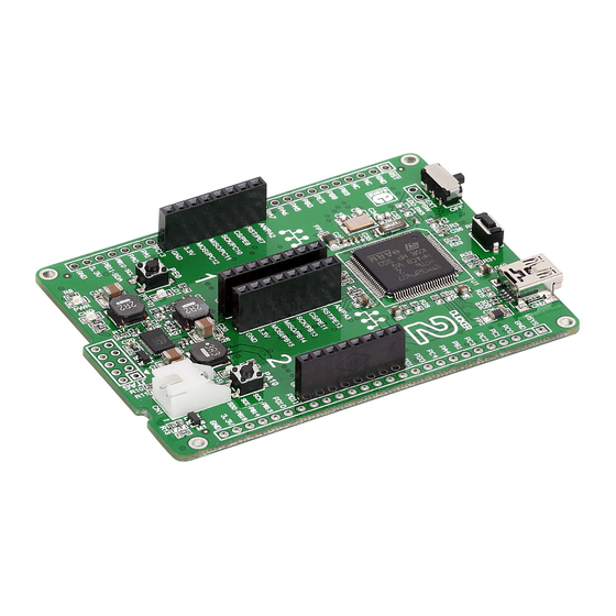
- Page 1 A compact starter kit with your favorite microcontroller and two mikroBUS sockets ™...
- Page 2 TO OUR VALUED CUSTOMERS I want to express my thanks to you for being interested in our products and for having confidence in MikroElektronika. The primary aim of our company is to design and produce high quality electronic products and to constantly improve the performance thereof in order to better suit your needs.
-
Page 3: Table Of Contents
Table of contents Introduction to clicker 2 for STM32 3.2 Programming with mikroProg programmer ™ Key features mikroProg Suite for ARM software ™ ® 1. Power supply 3.3 Programming with ST-LINK V2 programmer 2. STM32F407VGT6 microcontroller 4. Buttons and LEDs Key microcontroller features 5. -
Page 4: Introduction To Clicker 2 For Stm32
Introduction to clicker 2 for STM32 clicker 2 for STM32 is a compact dev. kit with two mikroBUS sockets for click board ™ connectivity. You can use it to quickly build your own gadgets with unique functionalities and features. It carries the STM32F407VGT6, a 32-bit ARM®... -
Page 5: Key Features
Key features ON/OFF switch Pads for connecting external ON/OFF switch Jumper for enabling RTC power supply 25 MHz crystal oscillator 32.768 KHz crystal oscillator 2x26 connection pads mikroBUS sockets 1 and 2 ™ Pushbuttons Additional LEDs LTC3586 USB power manager IC Indication LEDs RESET button USB mini-B connector... - Page 6 VCC-BAT VCC-3.3V VCC-3.3V VCC-3.3V VCC-3.3V VCC-3.3V VCC-3.3V VCC-3.3V VCC-3.3V VCC-3.3V VSYS VCC-3.3V VCC-5V VCC-3.3V VCC-5V HDR1 HDR2 2.2uF VCC-3.3V BATT CONN RESET# 100nF 100nF 100nF 100nF 100nF 100nF 100nF 100nF 10uF 10uF PC0-AN AVCC PC1-AN 100K PA2-MB1_AN PE9-MB1-PWM PA3-MB2_AN PD12-MB2-PWM PC2-AN PB9-PWM PE7-MB1_RST...
-
Page 7: Power Supply
1. Power supply USB power supply You can supply power to the board with a Mini-B USB cable provided in the package. On-board voltage regulators provide the appropriate voltage levels to each component on the board. Power LED (GREEN) will indicate the presence of power supply. - Page 8 LDO3V3 LDO3V3 VCC-3.3V VCC-3.3V VCC-3.3V LDO3V3 LDO3V3 AVCC VCC-3.3V LD4B JS202011AQN VCC-BAT VCC-BAT 22uF 10nF PD4-BATSTAT PWR-EN 100nF 2.2uF PB12-SENSEL 100nF DMP2305U 100K VSYS VSYS DMP2305U 100K VSYS LTC3586 PC5-VSENSE 2.2uF 2.2uF HDR1 HDR2 100K 100nF VCC-BAT SWCD3 PWR-EN PWR-EN VSYS VOUT VOUT3...
-
Page 9: Stm32F407Vgt6 Microcontroller
2. STM32F407VGT6 microcontroller The clicker 2 for STM32 development tool comes with the STM32F407VGT6 device. This 32-bit high performance microcontroller is rich with on-chip peripherals and features 1 MB of Flash and 192+4 KB of SRAM. It has integrated full speed USB 2.0. -
Page 10: Programming The Microcontroller
3. Programming the microcontroller Figure 3-1: STM32F407VGT6 microcontroller The microcontroller can be programmed in three ways: Using USB HID mikroBootloader, Using external mikroProg for STM32 programmer ™ Using external ST-LINK V2 programmer ™ Page 10... -
Page 11: Programming With Mikrobootloader
Firmware File folder the Reset button on your clicker 2 for STM32. Click the Connect button within 5s to enter the bootloader mode, otherwise clicker 2 STM32 STM32F407VG USB HID Bootloader v1.310.hex existing microcontroller program will execute. HEX File Page 11... -
Page 12: Step 2 - Browsing For .Hex File
step 2 – Browsing for .HEX file step 3 – Selecting .HEX file Figure 3-4: Selecting HEX Figure 3-3: Browse for HEX Click the Browse for HEX button and from a Select .HEX file using open dialog window. pop-up window (Figure 3.4) choose the .HEX file Click the Open button. -
Page 13: Step 4 - Uploading .Hex File
step 4 – Uploading .HEX file Figure 3-5: Begin uploading Figure 3-6: Progress bar To start .HEX file bootloading click the Progress bar enables you to monitor .HEX file uploading. Begin uploading button. Page 13... -
Page 14: Step 5 - Finish Upload
step 5 – Finish upload Figure 3-7: Restarting MCU Figure 3-8: mikroBootloader ready for next job Click OK button after the uploading process is finished. Press Reset button on clicker 2 for STM32 board and wait for 5 seconds. Your program will run automatically. Page 14... -
Page 15: Programming With Mikroprog ™ Programmer
3.2 Programming with mikroProg programmer ™ The microcontroller can be programmed with external mikroProg for STM32 ™ programmer and mikroProg Suite for ARM software. ™ ® The external programmer is connected to the development system via 2x5 JTAG connector soldered on the CN3 connector pads, Figure 3-9. -
Page 16: Mikroprog Suite For Arm Software
mikroProg Suite for ARM software ™ ® On-board mikroProg programmer requires special programming software called mikroProg Suite ™ ™ for ARM . This software is used for programming of all supported microcontroller families with ® Cortex -M3 and Cortex -M4 cores. The software has an intuitive interface and SingleClick ®... -
Page 17: Programming With St-Link V2 Programmer
3.3 Programming with ST-LINK V2 programmer The microcontroller can also be In order to adjust the ST-LINK V2 programmer to ™ programmed with the ST-LINK V2 be connected to the development system, it is programmer and mikroProg Suite ™ necessary to provide the appropriate adapter for ARM software. - Page 18 VCC-3.3V VCC-3.3V 2.2uF VCC-3.3V 100nF 100nF AVCC 100K VCC-3.3V 100nF 100nF PB12 PB13 PB14 PA0-WKUP VCC-3.3V VCC-3.3V PB15 VDDA VREF+ GNDA PD10 100nF 100nF PD11 PD12 22pF 22pF PD13 100pin TQFP PD14 RESET# PD15 NRST VCC-3.3V VCC-3.3V OSC_OUT STM32F407VGT6 OSC_OUT 25MHz OSC_IN OSC_IN...
-
Page 19: Buttons And Leds
4. Buttons and LEDs The board also contains a reset button and buttons and LEDs, a pair of as well as an ON/OFF switch. The Reset button is used to manually reset the microcontroller—it generates a low voltage level on the microcontroller’s reset pin. - Page 20 VCC-3.3V VCC-3.3V VCC-3.3V 2.2uF VCC-3.3V 100nF 100nF AVCC 100K RESET# VCC-3.3V 100nF 100nF 100nF PB12 PB13 PB14 PA0-WKUP VCC-3.3V VCC-3.3V PB15 VDDA VREF+ GNDA PD10 100nF 100nF PD11 PD12 22pF 22pF PD13 100pin TQFP PD14 RESET# PD15 NRST OSC_OUT VCC-3.3V VCC-3.3V STM32F407VGT6 OSC_OUT...
-
Page 21: Power Management And Battery Charger
5. Power management and battery charger clicker 2 for STM32 features LTC®3586-2, a highly integrated power management and battery charger IC that includes a current limited switching PowerPath manager. When you solder the onboard zero-ohm J1 jumper to the LDO position (Figure 6-1), the LTC®3586-2 will provide an independent, steady power supply to the MCUs... -
Page 22: Oscillators
6. Oscillators The STM32F407VGT6 microcontroller is equipped with an internal 16MHz RC oscillator that provides a stable clock signal. Since the chips have an integrated PLL, this base frequency is suitable for further clock multiplication. Board also contains an additional 25MHz crystal oscillator, as well as a 32.768kHz one, which provides an external clock for the internal RTCC module. - Page 23 2.2uF VCC-3.3V VCC-3.3V VCC-3.3V AVCC 100K 100nF 100nF VCC-3.3V PB12 PB13 PB14 PA0-WKUP PB15 VDDA 100nF 100nF VREF+ GNDA PD10 PD11 PD12 22pF 22pF VCC-3.3V VCC-3.3V PD13 100pin TQFP PD14 PD15 NRST OSC_OUT STM32F407VGT6 OSC_OUT 25MHz OSC_IN OSC_IN 100nF 100nF OSC32_OUT OSC32_IN PC15/OSC32_OUT...
-
Page 24: Usb Connection
7. USB connection STM32F407VGT6 microcontrollers has an integrated USB module, which enables you to implement USB communication functionality to your clicker 2 board. Connection with target USB host is done over a Mini-B USB connector which is positioned next to the battery connector. Figure 7-1: Connecting USB cable to clicker 2... - Page 25 VCC-3.3V VCC-3.3V VCC-3.3V VCC-3.3V VCC-3.3V 2.2uF VCC-3.3V AVCC 100K 100nF 100nF 100nF 100nF 100nF 100nF VCC-3.3V VCC-3.3V VCC-3.3V VCC-3.3V PB12 PB13 100nF 100nF 10uF 10uF PB14 PA0-WKUP PB15 VDDA VREF+ GNDA PD10 PD11 PD12 22pF 22pF PD13 100pin TQFP PD14 PD15 NRST OSC_OUT...
-
Page 26: Pads
8. Pads VCC-3.3V VCC-3.3V VCC-3.3V VCC-3.3V VCC-3.3V VCC-3.3V VCC-3.3V VCC-3.3V VCC-3.3V 100nF 100nF 100nF 100nF 100nF 100nF 100nF 100nF 10uF 10uF 2.2uF VCC-3.3V AVCC 100K VSYS HDR1 HDR2 RESET# PC0-AN PB12 PC1-AN PB13-SPI2_SCK PA1-UART4_RX PB13 PC2-AN PB14-SPI2_MISO PA0-UART4_TX PB9-PWM PB14 PA0-WKUP PC3-AN PB15-SPI2_MOSI... -
Page 27: Pinout
9. Pinout Reset pin VSYS System power supply Reference Ground Reference Ground Analog Lines PWM lines Interrupt Lines Digital I/O lines PD15 PD14 PD13 Digital I/O lines PC13 PD11 PD10 UART4 Lines PB13 PB10 PB14 SPI2 Lines C2 Lines PB11 PB15 3.3V power supply 3.3V power supply... -
Page 28: Mikrobus ™ Pinout
9.1 mikroBUS pinouts ™ Having two mikroBUS sockets and an additional connection pad, clicker 2 for STM32 utilizes all of the STM32F407VGT6’s I/Os. ™ Each of the three UART outputs has its own separate connection pin (either on mikroBUS 1 or 2, or on the 2x26 connection pad). ™... -
Page 29: Click ™ Boards Are Plug And Play
10. click boards are plug and play! ™ Up to now, MikroElektronika has released more than 90 mikroBUS ™ compatible click boards. On the ™ average, one click board is released per week. It is our intention to provide you with as many add-on... - Page 30 RFid click Relay click 8x8 click FM click Bluetooth2 click Thunder click USB SPI click ™ ™ ™ ™ ™ ™ ™ BarGraph click 7seg click THERMO click Gyro click EEPROM click LightHz click Pressure click ™ ™ ™ ™ ™...
-
Page 31: Dimensions
11. Dimensions Page 31... - Page 32 No part of this manual, including product and software described herein, may be reproduced, stored in a retrieval system, translated or transmitted in any form or by any means, without the prior written permission of MikroElektronika. The manual PDF edition can be printed for private or local use, but not for distribution.
- Page 33 If you want to learn more about our products, please visit our web site at www.mikroe.com If you are experiencing some problems with any of our products or just need additional information, please place your ticket at www.mikroe.com/support If you have any questions, comments or business proposals, clicker 2 for STM32 manual do not hesitate to contact us at office@mikroe.com...
- Page 34 Mouser Electronics Authorized Distributor Click to View Pricing, Inventory, Delivery & Lifecycle Information: Mikroe MIKROE-1685...
Need help?
Do you have a question about the CLICKER 2 STM32 and is the answer not in the manual?
Questions and answers