Table of Contents
Advertisement
Quick Links
Advertisement
Table of Contents

Related Manuals for mikroElektronika EasyPIC5


Summary of Contents for mikroElektronika EasyPIC5
-
Page 2: Table Of Contents
CONTENTS EasyPIC5 KEY FEATURES CONNECTING THE SYSTEM INTRODUCTION Switches Jumpers MCU Sockets Power Supply On-Board USB 2.0 Programmer Oscillator mikroICD (Hardware In-Circuit Debugger) LEDs Reset Circuit Push Buttons 7-segment Displays 2x16 Character LCD Graphic LCD Touch Panel RS-232 Communication Module... -
Page 3: Easypic5 Key Features
1. External power supply connector 8 - 16V AC/DC; and LCD and GLCD backlights; 2. Power supply selector. It is possible to use external or 14. EasyPIC5 supports microcontrollers in DIP8, DIP14, USB power supply. When using USB port, there is no DIP18, DIP20, DIP28 and DIP40 packages;... -
Page 4: Connecting The System
PICflash programmer manual. After these four steps, your EasyPIC5 is successfully installed and ready for use. You can read a program from the chip or write another one into it. The product CD provides numerous simple program examples to make... -
Page 5: Introduction
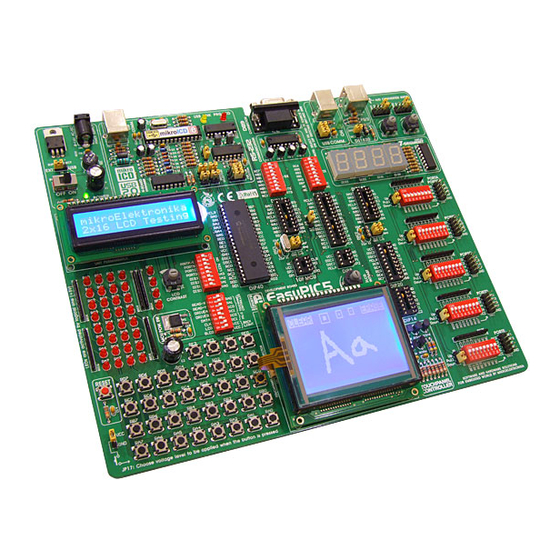
The user can therefore concentrate on software development only. Figure 1 illustrates the EasyPIC5 development system. There are identification marks next to each component on a silkscreen, both on the top and bottom. These marks describe connection to the microcontroller, operation modes and provide additional useful information so that there is almost no need for additional schematics. -
Page 6: Switches
SWITCHES The EasyPIC5 development system features a number of peripheral devices. In order to enable these before programming, the appropriate jumpers or switches have to be properly set. Switches are mechanical devices used to establish or break connection between two contacts. As for this sys- tem, switches are grouped in nine DIP switches. -
Page 7: Jumpers
JUMPERS Similarly, jumpers are used to break or establish connection between two points. Under the plastic cover of a jumper, there is a metal contact which establishes connection when the jumper is placed over two pins. Figure 3 Jumper as a switch Jumper is commonly used as a selector between two possible connections via 3-pin connector. -
Page 8: Mcu Sockets
MCU SOCKETS The EasyPIC5 comes with a 40-pin microcontroller PIC16F887. The user can remove this microcon- troller and fit another one in DIP40, DIP28, DIP20, DIP18, DIP14 or DIP8 package into MCU socket. Figure 5 MCU sockets Note: There are two DIP18 sockets with different pinouts (DIP18A and DIP18B). If you use 18-pin micro- controllers, make sure to select the right socket. - Page 9 The microcontroller pins are routed to various peripherals as illustrated in Figure 6. All MCU ports 1 1 0 0 are directly connected to Direct Port Access 2x5 (10-pin) connectors. These are normally used for connecting external peripherals to the board or as points for digital logic probe connecting. All ports are connected to LEDs and push buttons, which allows you to easily test and monitor dig- ital pin state.
-
Page 10: Power Supply
POWER SUPPLY 1 1 1 1 The EasyPIC5 can use one out of two power supply sources - PC power supply over USB cable (by default) or external power supply (external AC/DC power adapter). When using power supply over USB cable, jumper J6 should be set in the right-hand position. -
Page 11: On-Board Usb 2.0 Programmer
1 1 2 2 There is no need to use external equipment during pro- gramming as the EasyPIC5 development system has its own on-board USB 2.0 programmer. All you need to do is to connect the system to PC using the USB cable. Then,... - Page 12 1 1 3 3 J8 and J9 for DIP28, DIP40, Figure 12 DIP18A and DIP18B J8 and J9 for DIP8, Figure 13 DIP14 and DIP20 When using DIP28, DIP40, DIP18A and DIP18B sockets, jumpers J8 and J9 should be set in the upper position (default) as shown in Figure 12.
-
Page 13: Oscillator
OSCILLATOR 1 1 4 4 The EasyPIC5 enables you to use microcontrollers fitting eight different sockets. Since these are not close to each other, there are two on-board clock oscillators. One of them, denoted by OSC1, is con- nected to DIP28, DIP40, DIP18A and DIP18B sockets. Another one, denoted by OSC2, is connected to DIP8, DIP14 and DIP20 sockets. - Page 14 On some of the microcontrollers, oscillator input pins can also be used as digital input/output pins. 1 1 5 5 In order to implement this feature, the EasyPIC5 has jumpers enabling MCU to be connected to either oscillator or digital I/O pins. Refer to the schematic of the OSC oscillator in Figure 16.
-
Page 15: Mikroicd (Hardware In-Circuit Debugger)
(SFRs) and EEPROM while the program is running. MikroICD can be used with any PIC compiler manufactured by MikroElektronika (mikroC, mikroBa- sic or mikroPascal). You just have to select the appropriate build type (Release or ICD Debug), build a project, program the MCU and run debugger. -
Page 16: Leds
LEDs 1 1 7 7 Light Emitting Diodes (LEDs) are components used for displaying pin digital state. The EasyPIC5 has 36 LEDs connected to the microcontroller PORTA, PORTB, PORTC, PORTD and PORTE. Each group of eight port LEDs can be enabled or disabled using switches of the DIP switch SW6. - Page 17 Figure 19 illustrates the connection between LEDs and PORTB. Resistors are serially connected to 1 1 8 8 the LEDs in order to limit their current. In this case the resistor value is 1K. Figure 19 LEDs circuit diagram...
-
Page 18: Reset Circuit
RESET CIRCUIT 1 1 9 9 Apart from 36 push buttons provided on the board, there is one red button on the far left marked as RESET. As its name suggests it is used for MCU reset. Reset button Figure 20 As seen in Figure 21, the microcontroller MCLR pin is connected to the programmer instead of being directly connected to the RESET button. -
Page 19: Push Buttons
PUSH BUTTONS 2 2 0 0 The EasyPIC5 has 36 push buttons which can be used to change states of digital inputs on the microcontroller ports. Con- nection between buttons and PORTA, PORTB, PORTC, PORTD and PORTE is shown in Figure 22. Jumper J17 deter-... - Page 20 2 2 1 1 Referring to Figure 24, jumper J2 is set to pull-up, so that pull-up resistor pulls the microcontroller pin RB4 to +5V. By pressing the button, the RB4 pin is connected to ground via J17. Accordingly, only when the button is pressed the microcontroller senses a logic zero (0).
-
Page 21: 7-Segment Displays
7-SEGMENT DISPLAYS 2 2 2 2 The EasyPIC5 has four 7-segment displays set up to operate in multiplex mode. Data lines are connected to PORTD, while each display is enabled by four PORTA bits. Figure 26 7-segment displays Common marking of... -
Page 22: 2X16 Character Lcd
Figure 28 2x16 LCD in 4-bit mode Figure 29 2x16 LCD circuit diagram Note: Have in mind that LCD should be placed or removed from the EasyPIC5 only after the power is turned off. -
Page 23: Graphic Lcd
128x64 pixels.The GLCD contrast can be adjusted using the potentiometer P3 placed right above the GLCD. Figure 30 GLCD Figure 31 GLCD circuit diagram Note: Have in mind that GLCD should be placed or removed from the EasyPIC5 only after the power is turned off. -
Page 24: Touch Panel
TOUCH PANEL 2 2 5 5 Touch panel is a tin, self-adhesive, transparent panel which could be placed over the screen of graphic LCD. It consists of two separate foils which form a “sandwich” structure. It is very sensi- tive to press so that even a soft touch causes some changes on the output signal. -
Page 25: Rs-232 Communication Module
RS-232 COMMUNICATION MODULE 2 2 6 6 RS-232 communication module enables point-to-point data trans- fer. It is commonly used in data acquisition applications to transfer data between the microcontroller and PC. Since the voltage levels of the microcontroller and PC are not directly compatible with each other, a level converter, such as MAX232, must be used. -
Page 26: Usb Communication Module
2 2 7 7 USB communication connector is placed in the upper right corner of the EasyPIC5. It is used with PIC microcontrollers having USB support,such as PIC18F2450 or PIC18F4550. Note that this USB connector cannot be used for programming. In order to make con- nection between the microcontroller and USB connector, the J12 jumper group should be set in the right-hand position. -
Page 27: Ps/2 Communication Module
PS/2 COMMUNICATION MODULE 2 2 8 8 PS/2 connector allows the EasyPIC5 to be directly connected to devices such as PC, keyboard or mouse. The PS/2 communication is of half-duplex type. It means that the microcontroller can be connected to a keyboard to capture pressed keys or to a PC to act as a keyboard. -
Page 28: Ds1820 Digital Thermometer
-55°C and 125°C with 0.5°C accuracy. It must be properly placed in the 3-pin socket provided on the EasyPIC5, with its rounded side directed to the right, as marked on the board (refer to the Figure 41 below). Otherwise, the DS1820 could be permanently damaged. -
Page 29: A/D Converter Test Inputs
Basically, you can measure any analog signal that fits in the range acceptable by PIC (0 - VCC). The EasyPIC5 development system has two potentiometers used to adjust the level of analog signals in order to test the operation of analog-to-digital converter (ADC). - Page 30 3 3 1 1 Pull-up/down resistors on PORTA analog input pins should be disabled using the DIP switch SW1. Potentiometer P1 is con- nected to the RA2 pin and potentiometer P2 to the RA3 pin. Figure 43 A/D Converter input circuit diagram Note: When the both potentiometers are in use, be sure that jumpers J15 and J16 do not select the same pin.
-
Page 31: Direct Port Access Connectors
DIRECT PORT ACCESS CONNECTORS 3 3 2 2 All microcontroller input/output pins can be accessed via IDC-10 connectors (2x5) placed along the right side of the board. For each microcontroller port there is one connector providing up to eight port pins and two additional pins connected to VCC and GND. These connectors can be used to connect the system to external peripherals such as Serial Ethernet, Compact Flash, MMC/SD, ADC, DAC, CAN, RTC, RS-485 etc. - Page 32 3 3 3 3 Figure 46 PORTB connection circuit diagram...
- Page 33 EasyPIC5 comes with PIC16F887 mikroE product CD with software Cables: USB cable Documentation: User manual for EasyPIC5, driver installation guide Installing USB MMC/SD multimedia card drivers, manual for PICflash programmer and manual for mikroICD System specifications: USB programmer: USB type B...
Need help?
Do you have a question about the EasyPIC5 and is the answer not in the manual?
Questions and answers
I choose to flash a pic16F628 but the picFlash[v7.11] detect a pic12F508. I tried with other pic16F628 but the result is the same
The issue occurs because the PICflash v7.11 programmer misidentifies the microcontroller. This can happen if the jumper settings on the EasyPIC5 board are incorrect. Specifically, jumpers J8 and J9 must be set correctly based on the microcontroller socket in use. If these jumpers are not in the correct position for a PIC16F628, the programmer may detect the wrong microcontroller, such as a PIC12F508. Ensuring the correct jumper configuration for the PIC16F628 should resolve the issue.
This answer is automatically generated
@Mr. Anderson thank you Mr.Anderson for your replay, to clarify I put the J8-J9 jumpers as the the picture shows, also I don't have problem with other pic like 16f887 or 16f84 , using the same configuration
@Mr. Anderson. I discovered that taking out the lcd display, the booard easypic5 , it reconize without any problem the pic 16f628A. this behavior is only in this pic , its very strange