
Related Manuals for mikroElektronika CLICKER 2 FOR FT90X


Summary of Contents for mikroElektronika CLICKER 2 FOR FT90X
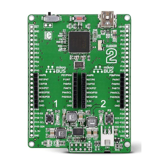
- Page 1 A compact starter kit with your favorite microcontroller and two mikroBUS sockets ™...
- Page 2 To our valued customers I want to express my thanks to you for being interested in our products and for having confidence in MikroElektronika. The primary aim of our company is to design and produce high quality electronic products and to constantly improve the performance thereof in order to better suit your needs.
-
Page 3: Table Of Contents
Table of Contents Introduction to clicker 2 for FT90x 3.2 Programming with mikroProg ™ Key features programmer 1. Power supply mikroProg Suite software ™ 2. FT900 microcontroller 4. Buttons and LEDs Key microcontroller features 5. Power management and battery charger 20 3. -
Page 4: Introduction To Clicker 2 For Ft90X
Introduction to clicker 2 for FT90x Clicker 2 for FT90x is a 1x8 female headers with SPI, compact dev. kit with two C, UART, RST, PWM, Analog mikroBUS sockets for click and Interrupt lines as well as ™ ™ board connectivity. You can 3.3V, 5V and GND power lines. -
Page 5: Key Features
Key features ON/OFF switch Pads for connecting external ON/OFF switch FT900Q 32.768 kHz crystal oscillator 12 mHz crystal oscillator 2x26 connection pads mikroBUS sockets 1 and 2 ™ Pushbuttons Additional LEDs LTC3586 USB power manager IC Power and Charge indication LEDs RESET button USB mini-B connector Li-Polymer battery connector... - Page 6 VCC-5V VCC-5V VCC-3.3V VCC-USB DMP2305U 2.2uH VCC-3.3V VCC-3.3V VCC-USB LDO3V3 88K7 10pF 22uF 10nF R24 100 FERRITE FSRC USB-DET VCC-USB VBUS USB-D_N 0Ω ADC2-GPIO7 USB-D_P 16K9 10uF 22uF 100nF VSYS 10nF USB MINIB clicker 2 for FT90x schematic Page 6...
-
Page 7: Power Supply
1. Power supply USB power supply Battery power supply You can also power the board using a Li-Polymer battery, via on-board battery connector. On-board battery charger circuit enables you to charge the battery over USB connection. LED diode (RED) will indicate when battery is charging. Charging current is ~300mA and charging voltage is 4.2V DC. - Page 8 LDO3V3 LDO3V3 VCC-3.3V VCC-3.3V VCC-3.3V LDO3V3 LDO3V3 VSYS VCC-BAT VCC-BAT LD4B JS202011AQN 22uF 10nF BATT GPIO50-STAT CONN 10uF PWR-EN VSYS VSYS 100nF VSYS DMP2305U LTC3586-1 HDR1 HDR2 2.2uF 2.2uF VCC-BAT VCC-BAT VCC-BAT SWCD3 PWR-EN PWR-EN VSYS VOUT VOUT3 LTC3586 GPIO31-SENSEL VCC-USB VBUS VOUT3...
-
Page 9: Ft900 Microcontroller
2. FT900 microcontroller The FT90x clicker development tool comes with the FT900Q microcontroller. This 32-bit FT32 Core high performance microcontroller executes instructions from Shadow RAM, achieving true zero wait states at up to 100mHz, resulting in 310 DMIPS of performance. Key microcontroller features ∫... -
Page 10: Programming The Microcontroller
3. Programming the microcontroller Figure 3-1: FT900Q microcontroller The microcontroller can be programmed in three ways: Using USB HID mikroBootloader, Using external mikroProg for FT90x programmer ™ Page 10... -
Page 11: Programming With Mikrobootloader
Firmware To start, connect the USB cable, or if already connected press the Reset button File folder on your clicker 2 for FT90x. Click the Connect button within 5s to enter the Clicker 2 FT90x USB HID Bootloader v1.300.hex bootloader mode, otherwise existing microcontroller program will execute. -
Page 12: Step 2 - Browsing For .Hex File
step 2 – Browsing for .HEX file step 3 – Selecting .HEX file Figure 3-4: Selecting HEX Figure 3-3: Browse for HEX Click the Browse for HEX button and from a pop-up Select .HEX file using open dialog window. window (Figure 3.4) choose the .HEX file which will be uploaded to MCU memory. -
Page 13: Step 4 - Uploading .Hex File
step 4 – Uploading .HEX file Figure 3-5: Begin uploading Figure 3-6: Progress bar To start .HEX file bootloading click the Progress bar enables you to monitor .HEX file uploading. Begin uploading button. Page 13... -
Page 14: Step 5 - Finish Upload
Figure 3-7: Restarting MCU Figure 3-8: mikroBootloader ready for next job Click OK button after the uploading process is finished. Press Reset button on clicker 2 for FT90x board and wait for 5 seconds. Your program will run automatically. Page 14... -
Page 15: Programming With Mikroprog ™ Programmer
3.2 Programming with mikroProg ™ programmer The microcontroller can be programmed with external mikroProg for FT90x ™ programmer and mikroProg Suite for FT90x software. ™ ® The external programmer is connected to the development system via 2x5 connector Figure 3-9. mikroProg is a ™... -
Page 16: Mikroprog Suite ™ Software
mikroProg Suite for FT90x software ™ A standalone programming software utility called mikroProg Suite for FT90x is available as an ™ alternative to programming the MCU directly from the FT90x compiler. This software is used for programming of all supported FT90x microcontrollers. The software has an intuitive interface and SingleClick programming technology. - Page 17 VCC-3.3V VCC-3.3V VCC-3.3V VCC-3.3V VCC-1.2V 100nF 100nF 100nF VCC-3.3V VCC-3.3V 100nF 100nF GPIO17 HRREF RTC_X1 GPIO18 AGND 10pF GPIO19 H_DP 32.768KHz GPIO20 H_DM GPIO21 DRREF USB-D_P RTC_X2 GPIO22 D_DP VCC-1.2V VCC-1.2V USB-D_N 10pF GPIO23 D_DM FTDI GPIO24 VCC3V3 GPIO25 VCC1V2 GPIO26 4.7uF 100nF...
-
Page 18: Buttons And Leds
4. Buttons and LEDs The board also contains a reset button and a pair of buttons and LEDs, as well as an ON/OFF switch. The Reset button is used to manually reset the microcontroller — it generates a low voltage level on the microcontroller’s reset pin. - Page 19 VCC-3.3V VCC-3.3V VCC-3.3V VCC-3.3V VCC-3.3V VCC-1.2V RESET# 100nF 100nF 100nF 100nF VCC-3.3V VCC-3.3V 100nF 100nF GPIO17 HRREF RTC_X1 GPIO18-LD2 GPIO18 AGND 10pF GPIO19 H_DP 32.768KHz GPIO20 H_DM GPIO21 DRREF RTC_X2 GPIO22 D_DP VCC-1.2V VCC-1.2V 10pF GPIO23 D_DM FTDI GPIO24 VCC3V3 GPIO25 VCC1V2 GPIO26...
-
Page 20: Power Management And Battery Charger
5. Power management and battery charger Clicker 2 for FT90x features LTC®3586, a highly integrated power management and battery charger IC that includes a current Figure 5-2: power limited switching PowerPath manager. management and LTC®3586 also enables battery charging battery charger IC over a USB connection. -
Page 21: Oscillators
6. Oscillators Two onboard oscillators act as external sources for FT90x’s two system clocks. A 12 MHz oscillator provides a reference frequency output to the clock multiplier PLL. A a 32.768kHz oscilator provides a clock for the internal RTCC. Figure 6-1: Figure 6-2: 32.768 kHz crystal 12MHz crystal... - Page 22 RTC_X1 10pF 32.768KHz VCC-3.3V VCC-3.3V VCC-3.3V VCC-3.3V RTC_X2 10pF VCC-1.2V 100nF 100nF 100nF VCC-3.3V VCC-3.3V 100nF 100nF GPIO17 HRREF GPIO18 AGND GPIO19 H_DP GPIO20 H_DM GPIO21 DRREF GPIO22 D_DP VCC-1.2V VCC-1.2V GPIO23 D_DM FTDI GPIO24 VCC3V3 GPIO25 VCC1V2 GPIO26 4.7uF 100nF GPIO27 XI/CLKIN...
-
Page 23: Usb Connection
7. USB connection FT90x microcontrollers has an integrated USB module, which enables you to implement USB communication functionality to your clicker 2 board. Connection with target USB host is done over a Mini-B USB connector which is positioned next to the battery connector. - Page 24 RTC_X1 10pF 32.768KHz VCC-3.3V VCC-3.3V VCC-3.3V VCC-3.3V RTC_X2 10pF VCC-1.2V 100nF 100nF 100nF VCC-3.3V VCC-3.3V 100nF 100nF GPIO17 HRREF GPIO18 AGND GPIO19 H_DP VCC-1.2V VCC-1.2V GPIO20 H_DM GPIO21 DRREF USB-D_P GPIO22 D_DP USB-D_N GPIO23 D_DM GPIO24 FTDI VCC3V3 4.7uF 100nF GPIO25 VCC1V2 GPIO26...
-
Page 25: Pads
Most microcontroller pins are available for further connectivity via two 1x26 rows of connection pads on both sides of the clicker 2 for FT90x board. They are designed to match additional shields, such as Battery Boost shield, Gaming, PROTO shield and others. -
Page 26: Pinout
9. Pinout VSYS √ √ √ √ √ √ √ √ √ √ √ √ √ √ √ √ √ √ √ √ √ √ √ √ √ √ √ √ √ √ √ √ √ √ √ √ √ √... -
Page 27: Mikrobus Pinout
9.1 mikroBUS pinouts ™ Having two mikroBUS sockets and an additional connection pad, clicker 2 for FT90x utilizes all of the FT90x’s I/Os. Single UART, I C, and ™ SPI lines are shared between two mikroBUS sockets but are also available from the two 1x26 connection pads on the edges of the board. -
Page 28: Click ™ Boards Are Plug And Play
10. click boards are plug and play! ™ Up to now, MikroElektronika has released more than a 100 mikroBUS compatible ™ click boards. On the average, one click ™ board is released per week. It is our intention to provide you with as many add-... - Page 29 RFid click Relay click 8x8 click FM click Bluetooth2 click Thunder click USB SPI click ™ ™ ™ ™ ™ ™ ™ BarGraph click 7seg click THERMO click Gyro click EEPROM click LightHz click Pressure click ™ ™ ™ ™ ™...
-
Page 30: Dimensions
11. Dimensions Page 30... - Page 31 (including damages for loss of business profits and business information, business interruption or any other pecuniary loss) arising out of the use of this manual or product, even if MikroElektronika has been advised of the possibility of such damages.
- Page 32 ∫ If you have any questions, comments or business proposals, do not hesitate to contact us at office@mikroe.com Clicker 2 for FT90x manual ver 1.01a Designed by MikroElektronika Ltd.
Need help?
Do you have a question about the CLICKER 2 FOR FT90X and is the answer not in the manual?
Questions and answers