
Related Manuals for mikroElektronika MSP432 clicker


Summary of Contents for mikroElektronika MSP432 clicker
- Page 1 A compact starter kit with your favorite microcontroller and a socket for click add-on ™ boards. New ideas are just a click away.
- Page 2 TO OUR VALUED CUSTOMERS I want to express my thanks to you for being interested in our products and for having confidence in MikroElektronika. The primary aim of our company is to design and produce high quality electronic products and to constantly improve the performance thereof in order to better suit your needs.
-
Page 3: Table Of Contents
Table of contents 1. What is STM32 M4 clicker? step 4 – Uploading .HEX file 2. Power supply step 5 – Finish upload 3. STM32F415RG microcontroller Programming with mikroProg programmer ™ Key microcontroller features mikroProg Suite for ARM software ™ ®... -
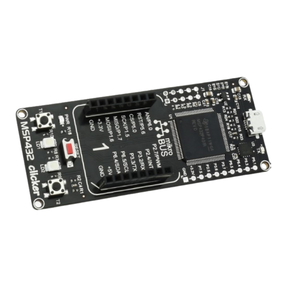
Page 4: What Is Stm32 M4 Clicker
1x8 female headers with SPI, C, UART, RST, PWM, Analog and Interrupt lines as well as 3.3V, 5V and GND power lines. Reset Button MSP432 clicker board can be powered over a USB cable. Power Indication LED Push Buttons... - Page 5 0.1µF P3.6_I2C_SDA P2.5_PWM VCC-3.3V VCC-5V P7.5_PWM AVCC MIKROBUS 1 VCC-3.3V P6.0_AN15 P2.7_PWM 32.768kHz 0.1µF 4.7µF P5.6_RST P2.4_INT P5.0_SPI_CS P3.2_UART_RX 12pF 12pF P1.5_SPI_CLK P3.3_UART_TX P1.7_SPI_MISO P6.5_I2C_SCL MISO P1.6_SPI_MOSI P6.4_I2C_SDA MOSI 3.3V MIKROBUS HOST CONN Figure 1-2: MSP432 clicker schematic Page 5...
- Page 6 VCC-USB 4.7k 10000pF 10118192-0001LF VCC-3.3V VCC-3.3V VCC-3.3V VCC-3.3V LED GREEN P1.2_UART_RX EN ADJ SPX3819M5 FT230x 10 F 0.10µF 10µF 0.10µF USB_TX USB_RX VCCIO P1.3_UART_TX GND PAD P8.2_FTD_RST VCC-USB VCC-5V VCC-3.3V 0.1µF 1µF 0.1µF Figure 1-3: MSP432 clicker schematic Page 6...
-
Page 7: Power Supply
2. Power supply Figure 2-1: Connecting USB power supply through CN1 connector When the board is powered up the power indication LED will be automatically turned on. The USB connection can provide up to 500mA of current which is more than enough for the operation of all on-board and additional modules. Page 7... - Page 8 VCC-3.3V VCC-USB VCC-USB VCC-3.3V LED GREEN EN ADJ SPX3819M5 10 F 0.10µF 10µF 0.10µF VCC-USB VCC-5V 0.1µF 1µF Figure 2-2: Power supply schematic Page 8...
-
Page 9: Stm32F415Rg Microcontroller
3. MSP432 microcontroller The MSP432 clicker development tool comes with the MSP432 microcontroller. This 32-bit high performance microcontroller is rich with on-chip peripherals and features 1024KB of Flash and 192KB of SRAM. It has integrated full speed USB 2.0. support. -
Page 10: Programming The Microcontroller
4. Programming the microcontroller Figure 4-1: MSP432 microcontroller The microcontroller can be programmed in two ways: Using USB HID mikroBootloader, Using external mikroProg for MSP432 programmer. ™ Page 10... -
Page 11: Programming With Mikrobootloader
Programming with mikroBootloader step 1 – Connecting MSP432 clicker You can program the microcontroller with a bootloader which is preprogrammed by default. To transfer .hex file from a PC to MCU you need bootloader software (mikroBootloader USB HID) which can be downloaded from: https://download.mikroe.com/examples/starter-... -
Page 12: Step 2 - Browsing For .Hex File
step 2 – Browsing for .HEX file step 3 – Selecting .HEX file Figure 4-3: Browse for HEX Figure 4-4: Selecting HEX Click the Browse for HEX button and from a Select .HEX file using open dialog window. pop-up window (Figure 3.4) choose the .HEX file Click the Open button. -
Page 13: Step 4 - Uploading .Hex File
step 4 – Uploading .HEX file Figure 4-5: Begin uploading Figure 4-6: Progress bar To start .HEX file bootloading click the Progress bar enables you to monitor .HEX file uploading. Begin uploading button. Page 13... -
Page 14: Step 5 - Finish Upload
5 – Finish upload Figure 4-7: Restarting MCU Figure 4-8: mikroBootloader ready for next job Click OK button after the uploading process is finished. Press Reset button on MSP432 clicker board and wait for 5 seconds. Your program will run automatically. Page 14... -
Page 15: Programming With Mikroprog ™ Programmer
Programming with mikroProg programmer ™ Figure 4-9: mikroProg connector ™ The microcontroller can be programmed with external mikroProg for MSP432 programmer and mikroProg Suite for ARM ™ ™ ® software. The external programmer is connected to the development system via 2x5 JTAG connector soldered on the CN2 connector pads, Figure 4-9. -
Page 16: Mikroprog Suite For Arm Software
mikroProg Suite for ARM software ™ ® On-board mikroProg programmer requires special programming software called mikroProg Suite ™ ™ for ARM . This software is used for programming of all supported microcontroller families with ® Cortex -M3 and Cortex -M4 cores. The software has an intuitive interface and SingleClick ®... - Page 17 VCC-3.3V 48MHz OSC1 OSC2 MCU_RST AVCC TASTER 2-PIN 12pF 12pF 0.1µF 4.7µF VCC-3.3V VCC-3.3V VCC-3.3V VCC-3.3V VCC-3.3V VCC-3.3V 0.1µF 4.7µF 0.1µF 4.7µF P10.1 P9.3 P10.2 P9.2 P10.3 DVCC2 P1.0_BUTTON1 P1.0 DVSS2 P1.1_BUTTON2 P1.1 P5.7 P1.2_UART_RX P5.6_RST P1.2 P5.6 P1.3_UART_TX P5.5_AN0 P1.3 P5.5 P1.4_SPI_CS...
-
Page 18: Buttons And Leds
5. Buttons and LEDs Figure 5-1: Two buttons, two LEDs and a reset button The board also contains a reset button and a pair of buttons and LEDs. Each of these additional peripherals are located in the bottom area of the board. Reset button is used to manually reset the microcontroller. Pressing the reset button will generate a low voltage level on microcontroller’s reset pin. - Page 19 VCC-3.3V 48MHz OSC1 OSC2 MCU_RST AVCC TASTER 2-PIN 12pF 12pF 0.1µF 4.7µF VCC-3.3V VCC-3.3V VCC-3.3V VCC-3.3V VCC-3.3V VCC-3.3V 0.1µF 4.7µF 0.1µF 4.7µF P10.1 P9.3 P10.2 P9.2 P10.3 DVCC2 P1.0_BUTTON1 P1.0 DVSS2 P1.1_BUTTON2 P1.1 P5.7 P1.2_UART_RX P5.6_RST P1.2 P5.6 P1.3_UART_TX P5.5_AN0 P1.3 P5.5 P1.4_SPI_CS...
-
Page 20: Click Boards Are Plug And Play
6. click boards are plug and play! Up to now, MikroElektronika has released more than 270 mikroBUS compatible ™ click Boards . On the average, one click ™ board is released per week. It is our intention to provide you with as many... - Page 21 RFid click Relay click 8x8 click FM click Bluetooth2 click Thunder click USB SPI click ™ ™ ™ ™ ™ ™ ™ BarGraph click 7seg click THERMO click Gyro click EEPROM click LightHz click Pressure click ™ ™ ™ ™ ™...
-
Page 22: Dimensions
7. Dimensions 75.6 2979 71.6 2819 2.54 Legend mils Mounting hole size Ø Ø 17.2 25.4 1000 Page 22... - Page 23 No part of this manual, including product and software described herein, may be reproduced, stored in a retrieval system, translated or transmitted in any form or by any means, without the prior written permission of MikroElektronika. The manual PDF edition can be printed for private or local use, but not for distribution.
- Page 24 If you want to learn more about our products, please visit our web site at www.mikroe.com If you are experiencing some problems with any of our products or just need additional information, please place your ticket at www.mikroe.com/support If you have any questions, comments or business proposals, do not hesitate to contact us at office@mikroe.com...
Need help?
Do you have a question about the MSP432 clicker and is the answer not in the manual?
Questions and answers