Table of Contents
Advertisement
Quick Links
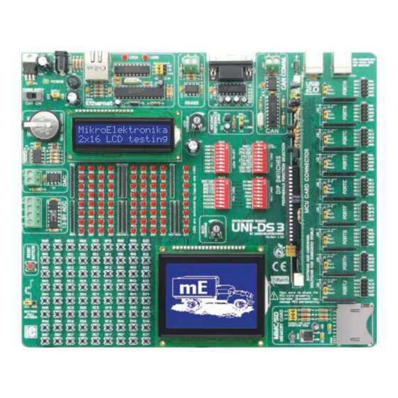
UNI-DS3
All MikroElektronika´s development systems represent irreplaceable tools for
programming and developing microcontroller-based devices. Carefully chosen
components and the use of machines of the last generation for mounting and
testing thereof are the best guarantee of high reliability of our devices. Due to
simple design, a large number of add-on modules and ready to use examples,
all our users, regardless of their experience, have the possibility to develop
their project in a fast and effi cient way.
™
™
3
User manual
Advertisement
Table of Contents

Related Manuals for mikroElektronika UNI-DS3


Summary of Contents for mikroElektronika UNI-DS3
- Page 1 ™ UNI-DS3 User manual All MikroElektronika´s development systems represent irreplaceable tools for programming and developing microcontroller-based devices. Carefully chosen components and the use of machines of the last generation for mounting and testing thereof are the best guarantee of high reliability of our devices. Due to...
- Page 2 TO OUR VALUED CUSTOMERS I want to express my thanks to you for being interested in our products and for having confi dence in mikroElektronika. The primary aim of our company is to design and produce high quality electronic products and to constantly improve the performance thereof in order to better suit your needs.
-
Page 3: Table Of Contents
UNI-DS3 Development System TABLE OF CONTENTS Introduction to UNI-DS3 Development System ................4 Key Features ............................. 5 1.0. Connecting the System to a PC ....................6 2.0. Placing MCU Card ........................7 3.0. Power Supply ..........................8 4.0. USB Connector for MCU Programmer ..................9 5.0 USB Communication Module ..................... -
Page 4: Introduction To Uni-Ds3 Development System
Every MCU card is also provided with appropriate programmer used for loading a hex code into the microcontroller. The UNI-DS3 development system may come with an MCU card with PIC ® , dsPIC ® , AVR ® , 8051, ARM ® or PSoC ®... - Page 5 UNI-DS3 Development System 1. Power supply voltage regulator 14. Socket for placing MCU card 2. Ethernet connector 15. DIP switches 3. Ethernet module 16. MMC/SD card slot 4. Alphanumeric display contrast adjustment 17. Graphic LCD display connector 5. Connector for RS485 communication 18.
- Page 6 MCU card with the microcontroller must be placed into the DIMM-168P socket prior to connecting the development system to a PC. Use the USB cable to connect the UNI-DS3 development system to a PC. One end of the USB cable, with a USB connector of B type, should be connected to the development system, as shown in Figure 1-2, whereas the other end of the cable with a USB connector of A type should be connected to the PC.
- Page 7 UNI-DS3 Development System The UNI-DS3 development system provides a DIMM-168P socket to place an MCU card into. All MCU cards are placed in the same UNI-DS3 card with a PIC microcontroller in TQFP80 package. Any card intended to be used on the UNI-DS3 development system may be placed instead of this one.
- Page 8 UNI-DS3 Development System 3.0. Power Supply The UNI-DS3 development system may use one of two power supply sources: 1. +5V PC power supply through the USB programming cable; and 2. External power supply source connected to an AC/DC connector provided on the development board.
-
Page 9: Usb Communication Module
USB Connector The USB connector (CN15) provided on the UNI-DS3 development system is connected to the on-board programmer on the MCU card. Every MCU card is supplied with a built-in programmer matching the relevant microcontroller. For example, the MCU card with a PIC microcontroller is supplied with the built-in programmer with mikroICD support. -
Page 10: Can Communication Module
UNI-DS3 Development System 6.0. CAN (Controller Area Network) is a communication standard primarily intended for use in automotive industry. It enables the microcontroller to communicate to a car device without using a host PC. In addition, such communication is widely used in industrial automation. -
Page 11: Rs232 Communication Module
PC and peripheral units. The RS232 serial communication is performed through a 9-pin SUB-D connector and the microcontroller USART module. The UNI-DS3 provides one RS232A port. Use switches marked as RX232A and TX232A as well as RX232B and TX232B on the DIP switch SW3 to enable port RS232A. The microcontroller pins used in such communication are marked as follows:... -
Page 12: Rs485 Communication Module
(up to 1200 m) and high tolerance to accompanying noise. The UNI-DS3 development system features a connector used for connecting devices which use RS485 communication. The LTC485 circuit acts as a transciever between an external device and the microcontroller. To enable connection between the microcontroller and the RS485 communication module, it is necessary to set switches 1, 2 and 3 on the DIP switch SW4 to the ON position. -
Page 13: Mmc/Sd Connector
UNI-DS3 Development System 9.0. The MMC/SD connector is used to enable memory cards to be interfaced with the microcontroller. To enable communication between memory card and microcontroller, it is necessary to adjust their voltage levels. Memory card is powered by the 3.3V power supply voltage (VCC3) generated by the REG2 voltage regulator, whereas the microcontroller’s power supply voltage is 5V (VCC). - Page 14 - ability to change the time format (12/24h) The real-time clock provided on the UNI-DS3 development system is used to generate an interrupt at pre-set time. In order to establish connection between the microcontroller and real-time clock it is necessary to set switch 1 on the DIP switch SW3, as well as switches 7 and 8 on the DIP switch SW4 to the ON position.
-
Page 15: Digital-To-Analog Converter (Dac)
UNI-DS3 Development System A digital-to-analog converter is a module used to convert a digital code into an analog voltage signal. The UNI-DS3 development system is equipped with the MCP4921 circuit which acts as a 12-bit digital-to-analog converter. This circuit provides a high accuracy of conversion as well as a high-quality signal despite noises occuring when it is used in industrial applications. - Page 16 An A/D converter is used for converting an analog signal into the appropriate digital value. A/D converter is linear, which means that converted number is linearly dependent on the input voltage value. The MCP3204 circuit is used as an A/D converter on the UNI-DS3 development system.
-
Page 17: Ethernet Module
UNI-DS3 Development System The UNI-DS3 development system is provided with an ethernet module. Its function is to provide an interface between the microcontroller and LAN (local area network). A stand-alone controller ENC28J60 enables ethernet communication on the development system. This circuit is used to transfer data from LAN to the microcontroller using serial communication.The 3.3V voltage is required for the operation of this circuit. -
Page 18: Leds
The UNI-DS3 uses LEDs with current I=1mA. There are 72 LEDs on the UNI-DS3 development system which visually indicate the state of each microcontroller I/O pin. An active LED indicates that a logic one (1) is present on the pin. In order to enable the pin state to be shown, it is necessary to select appropriate port (PORTA, PORTB, PORTC, PORTD, PORTE, PORTF, PORTG, PORTH or PORTJ) using the DIP switch SW1 and switch 1 on the DIP switch SW2. -
Page 19: Push Buttons
UNI-DS3 Development System The logic state of all microcontroller input pins may be changed by means of push buttons. Jumper J10 is used to determine the logic state to be applied to the desired microcontroller pin by pressing appropriate push button. Right next to the push buttons, there is a RESET button which is used to provide the MCLR pin with the microcontroller reset signal over the programmer provided on the MCU card. -
Page 20: X16 Lcd Display
16.0. 2x16 The UNI-DS3 development system provides an on-board connector for the alphanumeric 2x16 LCD display. This connector is linked to the microcontroller via pins D0, D1, D4, D5, D6 and D7 on the MCU card. Potentiometer P2 is used for display contrast adjustment. -
Page 21: 128X64 Graphic Lcd Display
CS2#, LCD-RS, LCD-RW, LCD-E, LCD-RST and D0-D7. It has a screen resolution of 128x64 pixels, which allows diagrams, tables and other graphic content to be displayed. Potentiometer P1 is used for the GLCD display contrast adjustment. The display backlight is automatically turned on by turning the UNI-DS3 development system on. Contrast adjustment... -
Page 22: I/O Ports
UNI-DS3 Development System 18.0. Along the right side of the development system, there are nine 10-pin connectors which are connected to the microcontroller’s I/O ports. Microcontroller pins used for programming are not directly connected to the appropriate 10-pin connectors, but via a multiplexer. - Page 23 UNI-DS3 Development System Pull-up/pull-down resistors enable you to set the logic level on all microcontroller’s input pins when they are in idle state. Such level depends on the position of the pull-up/pull-down jumper. The RB1 microcontroller pin with jumper J2 and the RB1 push button with jumper J10 are used here for the purpose of explaining the performance of pull-up/pull-down resistors.
-
Page 24: Mcu Card With 8051 Microcontroller
UNI-DS3 Development System The MCU card is provided with a socket for 8051 microcontrollers in DIP40 package. The AT89S8253 microcontroller normally delivered with the 8051 MCU card is placed into the DIP40 socket. In addition to this microcontroller, there are also other microcontrollers in DIP40 package such as AT89S51, AT89S52, AT89S53 and AT89S8252 that can be used here. - Page 25 UNI-DS3 Development System : MCU card with the DIMM-168p socket connection schematic MikroElektronika...
-
Page 26: Mcu Card With Avr Microcontroller
UNI-DS3 Development System The MCU card is provided with the ATmega128 microcontroller in 64-pin TQFP package. In addition to this microcontroller, there is also a built-in programmer AVRprog as well as the CN2 connector provided on the MCU card. Such connector is intended for connecting the external JTAG programmer. - Page 27 UNI-DS3 Development System : MCU card with the DIMM-168p socket connection schematic MikroElektronika...
- Page 28 UNI-DS3 Development System The MCU card is provided with the dsPIC6014A microcontroller in 80-pin TQFP package. In addition to this microcontroller, there is also a built-in programmer provided on the MCU card. To enable the programmer to operate properly, it is provided in the relevant manual and install driver for the programmer from the product CD.
- Page 29 UNI-DS3 Development System : MCU card with the DIMM-168p socket connection schematic MikroElektronika...
-
Page 30: Mcu Card With Dspic Microcontroller
UNI-DS3 Development System The MCU card is provided with a socket for PIC microcontrollers in DIP40 package. The PIC18F4520 microcontroller normally delivered with the PIC MCU card is placed into the DIP40 socket. In addition to this microcontroller, there are also other microcontrollers in DIP40 package such as PIC16F877A, PIC18F4550 etc. - Page 31 UNI-DS3 Development System : MCU card with the DIMM-168p socket connection schematic MikroElektronika...
-
Page 32: Mcu Card With Psoc Microcontroller
UNI-DS3 Development System The MCU card is provided with the PIC18F8520 microcontroller in 80-pin TQFP package. In addition to this microcontroller, there is also a built-in programmer with mikroICD support provided on the MCU card. To enable the programmer to operate the instructions provided in the relevant manual and install driver for the programmer from the product CD. - Page 33 UNI-DS3 Development System : MCU card with the DIMM-168p socket connection schematic MikroElektronika...
- Page 34 UNI-DS3 Development System The MCU card is provided with the CY8C27643 microcontroller in 48-pin SSOP package. In addition to this microcontroller, there is also a built-in programmer PSoCprog provided on the MCU card. To enable the PSoCprog programmer to operate properly, instructions provided in the relevant manual and install driver for the PSoCprog programmer from the product CD.
- Page 35 UNI-DS3 Development System : MCU card with the DIMM-168p socket connection schematic MikroElektronika...
-
Page 36: Mcu Card With Arm Microcontroller
UNI-DS3 Development System The MCU card is provided with the LPC2148 microcontroller in LQFP64 package. In addition to this microcontroller, the MCU card is also supplied with a battery used to power the microcontroller when the power supply is off. The LPC2148 microcontroller requires 3.3V generated by the REG1 voltage regulator. - Page 37 UNI-DS3 Development System : MCU card with the DIMM-168p socket connection schematic MikroElektronika...
- Page 38 UNI-DS3 Development System : MCU card with the DIMM-168p socket connection schematic : ARM MCU cad placed into the DIMM-168p socket MikroElektronika...
- Page 39 MikroElektronika shall assume no responsibility or liability for any errors, omissions and inaccuracies that may appear in this manual. In no event shall MikroElektronika, its directors, offi cers, employees or distributors be liable for any indirect, specifi c, incidental or consequential damages (including damages for loss of business profi...
- Page 41 Mouser Electronics Authorized Distributor Click to View Pricing, Inventory, Delivery & Lifecycle Information: MikroElektronika MIKROE-179...
Need help?
Do you have a question about the UNI-DS3 and is the answer not in the manual?
Questions and answers