
Related Manuals for mikroElektronika mikromedia for ARM


Summary of Contents for mikroElektronika mikromedia for ARM
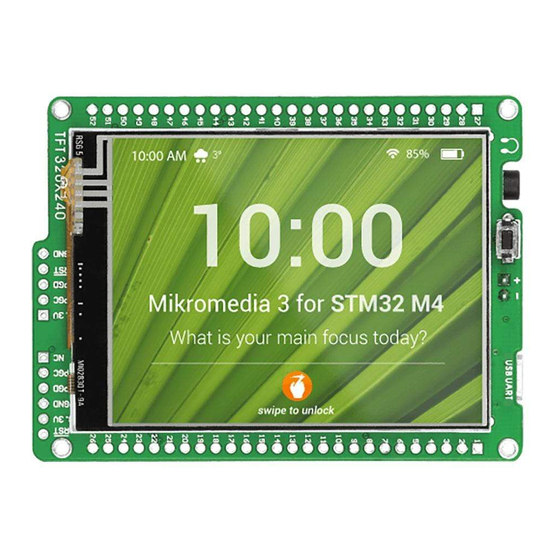
- Page 1 mikrome ia board for ARM Compact development system rich with on-board peripherals for all-round multimedia development on LPC2148 ARM7 device...
- Page 2 TO OUR VALUED CUSTOMERS I want to express my thanks to you for being interested in our products and for having confidence in Mikroelektronika. The primary aim of our company is to design and produce high quality electronic products and to constantly improve the performance thereof in order to better suit your needs.
-
Page 3: Table Of Contents
Table of Contents Introduction to mikromedia for ARM step 8 – Finished! Related material 4. LPC2148 Microcontroller Key Features Key microcontroller features System Specification 5. Programing with JTAG programmer/debugger 1. USB power supply 6. microSD Card Slot 2. Battery power supply 7. -
Page 4: Introduction To Mikromedia For Arm
ARM is a compact development system with lots of on-board peripherals which allow development of devices with multimedia contents. The central part of the system is a 32-bit ARM7 microcontroller LPC2148. The mikromedia for ARM features integrated modules such... -
Page 5: Related Material
Damage resistant mikromedia for ARM DVD with documentation protective box development system and examples mikromedia for ARM mikromedia for ARM USB cable user’s guide schematic Page 5... -
Page 6: Key Features
Connection Pads TFT 320x240 display USB MINI-B programmer connector LI-Polymer battery connector USB MINI-B device connector 3.5mm headphone connector Power supply regulator FTDI USB Uart controller VS1053 Stereo mp3 coder/decoder Power indicator LEDs Accelerometer LPC2148 microcontroller RESET button MicroSD Card Slot JTAG connector Page 6... -
Page 7: System Specification
System Specification power supply Over a USB cable (5V DC) power consumption 50mA in idle state (when on-board modules are off) board dimensions 8 x 6cm (3.14 x 2.36 inch) weight ~50g (0.11 lbs) Page 7... -
Page 8: Usb Power Supply
You can provide power supply to the board using either of the two miniUSB connectors. On board voltage regulator will make sure generate Figure 1-1: appropriate voltage levels to each part Powering your of the board. Power LED will indicate the mikromedia board presence of power supply. -
Page 9: Battery Power Supply
Figure 2-2: VCC-BAT VCC-5V VCC-BAT Li-polymer battery HDR3 connected to 2.2uF 10uF mikromedia M1X2 VCC-BAT VCC-5V for Charging Current approx. 250mA MBRS140T3 STAT VCC-5V STAT PROG Development system can be provided with power supply Li-Polymer using battery, via on-board battery connector. VBAT On-board battery charger circuit MCP73832... -
Page 10: Programing With In-System Programer
The microcontroller can be programmed with In-System Programmer supported in the hardware itself. Programmer USB connector is connected to the microcontroller through USB-UART connection. Figure 3-1: note You have to download and install drivers for your USB-UART Connecting USB connection before programming. Drivers can be found on cable to programming FTDI website: http://www.ftdichip.com/FTDrivers.htm connector... - Page 11 VCC-FTDI VCC-FTDI VCC-3.3 100nF 100nF 10uF P0.1 OSCO VCC-5V P0.0 OSCI P0.14 P0.21 P1.20 RTS# TEST P0.22 P0.17 VCC-3.3 VCCIO AGND RTXC1 P0.16 MCU-RST# P1.19 P0.15 MBRS340T3 DTR# RTXC2 P1.21 VCC-3.3 CBUS0 VCC3 VCC3 VCCA CBUS1 LPC2148 P1.18 P0.14 P0.25 P1.22 P0.13 VCC-FTDI...
-
Page 12: Settings
Device Manager on your PC contains informations on which COM port is used for USB communication with the mikromedia board for ARM. In this case the COM4 port is used. Right click on USB port, then on properties in the drop-down list. - Page 13 In pop-up window uncheck the Serial Enumerator option and click OK. note Steps 4 – 7 should be adjusted only once. Page 13...
-
Page 14: Step 1 - Choose Device
Figure 3-2: Flash Magic window after installation Programming is done using specialized programming Click on Select device button and browse for LPC2148 Flash Magic, which is available for download ARM7 software called microcontroller from family of microcontrollers. from the mikromedia for ARM webpage. Page 14... -
Page 15: Step 2 - Choose Com Port
step 2 – Choose COM port step 3 – Select baud rate Figure 3-4: Selecting COM Port Figure 3-5: Selecting baudrate COM Port 19200 bps From the dropdown list choose the assigned From the dropdown list select baudrate which to your mikromedia board after connecting it to your PC is the correct UART communication speed for mikromedia. -
Page 16: Step 4 - Specify Oscillator Freq
step 4 – Specify oscillator freq. step 5 – Browse for .hex file Figure 3-6: Specifying oscillator frequency Figure 3-7: Browsing for HEX file 12.000 MHz Browse Specify the value of on-board crystal oscillator Click on and find the HEX file you want to program your mikromedia with. -
Page 17: Step 6 - Erase Flash
step 6 – Erase Flash Figure 3-8: Erasing Flash memory before programming Figure 3-8: Write program Click on the Erase Flash icon in the main toolbar. first checkbox Tick the to specify erasing the entire flash. Click when Erasing is completed. Click on Erase button to start erasing flash. -
Page 18: Step 7 - Start Programming
step 7 – Start Programming step 8 – Finished! Figure 3-9: Program uploading Figure 3-10: Uploading is finished message We are now ready to program the microcontroller. When everything is completed, you will receive a Click on Start button to start uploading your program. in the status bar. -
Page 19: Lpc2148 Microcontroller
ARM development system comes with LPC2148 microcontroller. This high-performance 32-bit microcontroller with its integrated modules and in combination with other on-board modules is ideal for multimedia applications. Key microcontroller features - 32-bit architecture; - 512KB of program memory;... -
Page 20: Programing With Jtag Programmer/Debugger
Figure 5-1: Enabling JTAG using jumper Besides In-System programming mikromedia for ARM supports JTAG programming debugging interface. In order to use it, you have to solder 2x10 header to the JTAG connection JTAG jumper, pads on the back side of your mikromedia board. It is also necessary to solder and set the located right next to the JTAG connector (Figure 5-1), in order to enable this type of programming. - Page 21 P1.27 P1.31 P1.28 P1.29 P1.26 P1.30 P1.31 P1.28 P1.30 P1.29 P1.26 P1.27 MCU-RST# M2X10 Figure 5-2: JTAG interface schematics Page 21...
-
Page 22: Microsd Card Slot
Board contains microSD card slot for using microSD cards in your projects. It enables you to store large ammounts of data externally, thus saving microcontroller memory. microSD cards use Serial Peripheral Interface (SPI) for communication Figure 6-2: with the microcontroller. microSD card MICROSD CARD P1.24... -
Page 23: Accelerometer
The accelerometer is used to measure acceleration in three axis: x- y- and z-. The acceleromer’s function is defined by the user in the program loaded into the microcontroller. Communication between the accelerometer and the microcontroller is performed I 2 C over the interface. -
Page 24: Touch Screen
TFT 320x240 display The development system features a covered with a resistive touch panel. Together they form a functional unit called a touch screen. It enables data to be entered and displayed at the same time. The 262.000 diffe rent colors. TFT display is capable of showing data in Figure 8-1: Touch Screen... - Page 25 VCC-5V BC846 VCC-5V P0.13 VCC-3.3 BAT43 BC846 BC846 VCC-3.3 P0.21 P1.20 P0.22 P0.17 RTCX1 P0.16 VCC-3.3 P1.19 P0.15 RTCX2 P1.21 VCC3 VCC3 VCC-3.3 VCCA LPC2148 P1.18 P0.14 P0.25 P1.22 P0.13 TFT MODE P0.12 P1.17 P0.11 VCC-3.3 300K P0.28 P1.23 P0.10 P0.29 P0.30 P0.9...
-
Page 26: Audio Module
Figure 9-1: headphones connected with mikromedia The mikromedia for ARM features MP3 codec audio controller VS1053. This module enables audio reproduction by using stereo headphones connected to the Figure 9-2: Inserting system via a 3.5mm connector CN6. All functions of this module are controlled by 3.5mm headphones jack... - Page 27 VCC-1.8 VCC-1.8 VCC-1.8 LEFT LEFT 10uF 10uF 100nF 100nF 100nF 100K 3.3nF 3.3nF VCC-1.8 GPIO4 MICP MICN P0.18 XRESET GPIO1 100nF DGND0 GPIO0 10uF 10uF RIGHT VCC-1.8 CVDD0 XTEST 100K VCC-3.3 VS1053 R35 27 IOVDD0 CVDD3 P0.5 100K 100K 3.3nF 3.3nF CVDD1 P0.19...
-
Page 28: Usb Connection
LPC2148 microcontroller has integrated USB 2.0 module, which enables you to implement USB communication functionality of your mikromedia board. Connection with target USB host is done over miniUSB connector which is positioned next to the audio jack. There are two SMD jumpers, or zero-ohm resistors on board for selection of USB communication mode. - Page 29 NOT MOUNTED USB MINIB MBRS140T3 VCC-5V Figure 10-2: USB module connecting schematic Page 29...
-
Page 30: Pads
VCC-5V P0.4 P0.5 P0.7 P0.6 P0.8 P0.13 P0.9 P0.22 P0.21 P0.28 P0.10 P0.29 P0.12 P0.15 P0.14 P0.16 P0.23 P0.20 P0.25 P0.30 P0.31 P1.21 P1.16 P1.22 P1.17 P1.23 P1.24 P1.18 P1.25 P1.19 P1.26 P0.11 P1.20 P1.27 P0.1 P1.28 P0.0 P0.17 P0.2 P0.18 P0.3 P0.19... -
Page 31: Pinout
5V power supply Reset pin Reference Ground Reference Ground SCK0/CAP0.1/AD0.6 P0.4 left ch. audio out MISO0/MAT0.1/AD0.7 P0.5 right ch. MOSI0/CAP0.2/AD1.0 P0.6 P0.7 SSEL0/PWM2/EINT2 DTR1/MAT1.1/AD1.4 P0.13 P0.8 TXD1/PWM4/AD1.1 AD1.7/CAP0.0/MAT0.0 P0.22 P0.9 RXD1/PWM6/EINT3 AD0.1/CAP0.2/MAT0.2 P0.28 P0.21 PWM5/AD1.6/CAP1.3 AD0.2/CAP0.3/MAT0.3 P0.29 P0.10 RTS1/CAP1.0/AD1.2 RI1/EINT2/AD1.5 P0.15 P0.12 DSR1/MAT1.0/AD1.3... -
Page 32: Dimensions
80.90 mm (3.19") 73.01 mm (2.90") 3.45 mm 2.77 mm 2.54 mm (0.14") (0.10") (0.11") Page 32... - Page 33 No part of this manual, including product and software described herein, may be reproduced, stored in a retrieval system, translated or transmitted in any form or by any means, without the prior written permission of MikroElektronika. The manual PDF edition can be printed for private or local use, but not for distribution.
- Page 34 If you want to learn more about our products, please visit our website at www.mikroe.com If you are experiencing some problems with any of our products or just need additional information, please place your ticket at www.mikroe.com/en/support If you have any questions, comments or business proposals, do not hesitate to contact us at office@mikroe.com...
- Page 35 Mouser Electronics Authorized Distributor Click to View Pricing, Inventory, Delivery & Lifecycle Information: mikroElektronika MIKROE-780...
Need help?
Do you have a question about the mikromedia for ARM and is the answer not in the manual?
Questions and answers