Webasto Thermo Top Evo Installation Instructions Manual
Hide thumbs
Also See for Thermo Top Evo:
- User manual ,
- Installation documentation (64 pages) ,
- Manual (57 pages)
Table of Contents
Advertisement
Installation Instructions
Thermo Top Evo
English
-
ALWAYS carefully follow Webasto installation and repair instructions and heed all
WARNINGS.
-
Improper installation or repair of Webasto heating and cooling systems can cause fire or
the leakage of deadly carbon monoxide leading to serious injury or death.
-
Only genuine Webasto parts may be used. See also Webasto air and water heaters ac-
cessories catalogue.
-
Product produces temperatures high enough to ignite surrounding combustible materials
such as inflammable liquids, gases, vapor, and other combustible matter. The heater
must be switched off when loading or unloading flammable materials to prevent the risk
of explosion.
-
Webasto heating and cooling systems require qualified and/or professional installation
and repair technicians. Warranty shall be void if not installed by a certified or trained in-
staller/repair technician who has successfully completed the factory training course for
installation and repair of Webasto heating and cooling systems, and has been provided
with the technical information, tools and equipment required to properly complete the
necessary installation/repairs.
-
When heater is in use, the surface of the hot air outlet may become hot to the touch.
Contact with skin may cause burns.
Advertisement
Table of Contents

Related Manuals for Webasto Thermo Top Evo


Summary of Contents for Webasto Thermo Top Evo
- Page 1 Improper installation or repair of Webasto heating and cooling systems can cause fire or the leakage of deadly carbon monoxide leading to serious injury or death. Only genuine Webasto parts may be used. See also Webasto air and water heaters ac- cessories catalogue.
-
Page 2: Table Of Contents
11.2 Switch and Timer Connections......27 12 Wiring Diagrams ............31 3.4 Exhaust Syustem ............. 7 12.1 Thermo Top Evo with On/Off switch ....31 3.5 Combustion Air Inlet ..........7 3.6 Water Inlet ..............7 12.2 Thermo Top EVO with SmarTemp 2.0 ....32 3.7 Hot Water Outlet............ -
Page 3: Safety 1.1 Intended Use
If installed in special-purpose vehicles, the WARNING applicable regulations must be observed. Consult Danger of explosion with Webasto for alternative application options. In environments with combustible vapors, Meets FMCSA Motor Vehicle Requirements when flammable dust and hazardous goods installed in accordance with 49 CFR 393.77. For... -
Page 4: General Safety Information
1 | Safety General Safety Information Webasto Thermo & Comfort North America, Inc. is pleased to provide this installation manual. When used according to the guidelines stated in this manual, you can expect to provide years of trouble- free, enjoyable operation to your customer. -
Page 5: About This Document
This liability exclusion particularly applies to: Installation by untrained personnel Improper use Repairs not carried out by a Webasto service workshop Use of non-original spare parts Conversion of the heater without... -
Page 6: Regulations For Installing In Vehicle
3 | Regulations For Installing In Vehicle Regulations for Installing in Vehicle Read this installation manual in its entirety before 3.2.1 Parts of the vehicle body and other in- stalling this equipment. components in the immediate vicinity of Scope the heater must be protected against excessive heat and the danger of 3.1.1 Subject to the provisions of paragraph... -
Page 7: Exhaust Syustem
NOTE Failure to follow the installation instructions and the notes contained therein will lead to all liability being refused by Webasto. The same applies if repairs are carried out incorrectly or with the use of parts other than genuine Webasto service parts. This... - Page 8 3 | Regulations For Installing In Vehicle 3.7.1 Hot water hoses within the vehicle must be positioned or protected in such a way as to exclude all risk of injury or damage caused by direct contact. 3.7.2 The water outlet hose must be protected so that it cannot be obstructed by other objects or the flow of water through the hoses.
-
Page 9: Technical Data
4 | Technical Data Technical Data Technical Data - Thermo Top Evo Heater Thermo Top EVO ECE approval symbol E1 122R -00 0334 (Heater) E1 10R -03 6271 (EMC) Model Water heater with evaporator-type burner Heat flow (control range) 2.5 to 5 kW... -
Page 10: Technical Data - Enclosure Box
4 | Technical Data Technical Data - Technical Data - Enclosure Box Mounting Plate NOTE NOTE Drawing not to scale. Drawing not to scale. Fig. 2: Mounting Plate front view Fig. 1: Enclosure Box Dimensions... -
Page 11: Purpose And Vision
6.2.2 CE Mark The Thermo Top Evo water heater carries the CE mark since it complies with the regulations in force. The heater satisfies the requirements of class A. As a result, the following supplement applies: Installation in the engine compartment provides suf- ficient screening of radio interference. -
Page 12: Heater Components
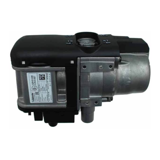
6 | Installation Example Heater Components Fig. 3: Thermo Top Evo Components Combustion Air Fan Exhaust Outlet Water Inlet Exhaust Gas Temperature Sensor Water Outlet Fuel Inlet Circulation Pump Air Inlet Fuel Metering Pump Control Unit Combustion Chamber Burner Motor... -
Page 13: Mounting The Heater To The Vehicle
Mounting the Heater to the Vehicle 6.4.1 Allowable Mounting Positions Fig. 4: Thermo Top EVO Orientation Fig. 6: Thermo Top Evo Standard Bracket Exploded View and Dimensions Fig. 5: Allowable Enclosure Kit Mounting Positions 6.4.2 Standard Mounting Bracket The heater must be fastened on the bracket with at least 3 (three) M5 bolts torqued to 6 lb-ft (8Nm). - Page 14 6 | Installation Example CAUTION Before drilling holes in the frame, consult the manufacturer for guidelines and restric- tions! Do not weld vehicle frame or flanges! 11.8 in (300 mm) 4.1 in (105 mm) Fig. 7: Mounting Hole Dimensions – Enclosure Box 9.6 in (244 mm) 3.7 in (94 mm) 0 .3 in (7.5 mm)
-
Page 15: Coolant System
Coolant Pump 7 Thermostat Thermo Top EVO Heater Connections Refer to Fig. 11, the contact surfaces of the O-rings in the heat exchanger must be clean. Apply a suit- able lubricant to the O-rings prior to installation in the heat exchanger. -
Page 16: Coolant System Connections
7 | Coolant System The heater should preferably be integrated into the NOTE coolant system close to the inlet of the vehicle heat IMPORTANT exchanger. The heater comes pre-assembled; however, Connect the heater to the vehicle coolant system as if direction of the water inlet or outlet shown in Coolant System on page 15. -
Page 17: Circulation Pump Installation
7 | Coolant System Inspecting the Coolant Circulation Pump Installation System After the heater and all coolant-carrying compon- ents have been installed, the entire coolant system must be checked for leaks with the system pressure specified by the vehicle manufacturer. To do this, start the engine and heater. -
Page 18: Fuel Supply
8 | Fuel Supply Fuel Supply Separate Fuel Tank Extracting Fuel from a Fuel A plastic or metal fuel tank may be installed. If the Tank use of a separate fuel tank is required, the fuel filler This separate fuel pickup precludes any effect of cannot be installed in the passenger compartment pressure. - Page 19 8 | Fuel Supply When extracting fuel, ensure that it is not blocked by check valves. In addition, make sure that the standpipe sits approximately 1 in (25mm) off the bottom of the fuel tank. This prevents the standpipe from picking up debris while also ensuring the heater never runs the vehicles fuel supply completely empty.
- Page 20 8 | Fuel Supply 9 - Pull up on the standpipe and tighten in place with the clamping nut (item 1). Do not overtighten the nut to prevent the rubber washing becoming dis- torted. Fuel Tank Fig. 18: Standpipe Installation - 4...
-
Page 21: Fuel System Overview
8 | Fuel Supply Fuel system overview Fig. 19: Fuel System Parameters Fuel Line Coupler Max Suction Height (A) = 3’ 3” (1m) Fuel Line Max Suction Length (A + B) = 9’ 9” (3m) Fuel Filter Max Delivery Length (C + D) = 28’ 3” (9m) Fuel Dosing Pump Max Delivery Height (D) = 9’... -
Page 22: Fuel Lines
8 | Fuel Supply Only steel, copper and plastic lines made of plasti- Fuel Lines cized, light and temperature-stabilized PA 11 or PA 12 (e.g. Mecanyl RWTL) may be used for the fuel CAUTION lines. Do not use biodiesel with copper fuel lines. The lines should not be routed downwards from the Failure to follow this instruction will result fuel metering pump to the heater. -
Page 23: Fuel Filter
8 | Fuel Supply Fuel Filter If there is a possibility of using dirty or contaminated fuel, a Webasto fuel filter should be installed. Ver- tical positioning is preferred where possible, how- ever horizontal is also acceptable. Note the installa- tion position and direction of flow. -
Page 24: Combustion Air System
9 | Combustion Air System Combustion Air System When installing the heater in the same compart- General ment as the vehicle’s fuel tank: Under no circumstances may the combustion air be – Combustion air must be drawn in from out- taken from areas occupied by people. -
Page 25: Exhaust System
10 | Exhaust System Exhaust System Exhaust System Safety Information It is also recommended to route the exhaust pipe with a downhill gradient. If this is not possible, con- WARNING densation drain holes 0.16” (4 mm) diameter can be Do not direct the exhaust outlet toward drilled at the lowest point(s). - Page 26 10 | Exhaust System The exhaust gas outlet must be oriented in line with Secure the exhaust line maximum 6 in. (150 mm) the following specifications: from the exhaust gas outlet so that the exhaust gas emerges at an angle of 90° ± 10° to the The exhaust gas must flow unobstructed.
-
Page 27: Electrical Connections
All electrical circuits must be protected with Route and secure the wire harness from the fuses or automatic circuit breakers. Webasto heater to battery box. WARNING Strip and crimp the wires using the supplied ring terminals to the positive (red) and negative Electrical cables and harnesses must be (brown) wire leads. - Page 28 11 | Electrical Connections 11.2.1 Rocker Switch Installation 11.2.2 SmarTemp 2.0 fx Installation Fig. 29: Rocker Switch Installation Fig. 30: SmarTemp 2.0 fx Connections 1 Red (power) 2 Brown (ground) 1 Red (power) 2 Brown (ground) Black or Grey (ON/ Green (diagnostic Black or Grey (ON/ Green (diagnostic...
- Page 29 11 | Electrical Connections 11.2.3 SmarTemp Control 3.0 and 3.0 Bluetooth Installation Connector end of Housing Pin No Description Pin No Description 12V / 24V power Brake signal input* Battery ground Open cavity Heater ON signal (coolant heater only W-bus communication Ambient temperature (air heaters Not used only)
- Page 30 11 | Electrical Connections The control element should be installed in a suitable location on a flat surface if possible, in a visible area. – Connect control element to existing connect- ors on heater-unit wiring harness. – Use the drilling dimensions to lightly mark the two mounting holes.
-
Page 31: Wiring Diagrams
12 | Wiring Diagrams 12 Wiring Diagrams 12.1 Thermo Top Evo with On/Off switch Fig. 33: Thermo Top Evo - With On / Off Switch... -
Page 32: Thermo Top Evo With Smartemp 2.0
12 | Wiring Diagrams 12.2 Thermo Top EVO with SmarTemp 2.0 Fig. 34: ThermoTop EVO with SmarTemp 2.0... -
Page 33: Thermo Top Evo With Smartemp 3.0
12 | Wiring Diagrams 12.3 Thermo Top Evo with SmarTemp 3.0 Fig. 35: ThermoTop EVO with SmarTemp Control 3.0 and 3.0 Bluetooth... -
Page 34: Thermo Top Evo With Enclosure Box
12 | Wiring Diagrams 12.4 Thermo Top EVO with Enclosure Box Fig. 36: Thermo Top EVO with Enclosure Box (on/off switch) -
Page 35: Tandem 717 With Smartemp
12 | Wiring Diagrams 12.5 Thermo Top EVO with Enclosure Box Fig. 37: Tandem 717 wiring diagram - SmarTemp 3.0 (Thermo Top Evo left, Air Top 2000STC right) -
Page 36: Wiring Diagram Legend
Plug con- to fuel metering pump nector, 2 pin Exhaust Tem- PT2000 Plug con- control module engine con- perature nector, 3 pin tact Sensor Table 2: Thermo Top Evo Wiring Diagram Coolant Temperature sensor for Legend Temperature coolant circuit Sensor... -
Page 37: Initial Operation
13 | Initial Operation 13 Initial Operation 13.1 Initial Operation Information WARNING Never operate the heater in closed rooms such as garages or workshops that do not have an ex- haust extraction unit. In workshops with exhaust extraction units, make sure that the exhaust extractor is fully opera- tional. - Page 38 6 Ensure heater and vehicle fuse boxes are closed and secure. Was the Webasto-supplied fuse block installed in a location that is pro- tected from water and/or moisture? 7 Ensure the blower motor resistor is securely mounted and has suffi- cient clearance from any plastic components and the battery.
- Page 39 13 | Initial Operation 2 Has muffler and exhaust tube been routed a safe distance from flammable material? 3 Ensure drain-holes are drilled in low bend areas of exhaust tube. 4 Ensure exhaust is venting a safe distance from any vehicle interior openings.
-
Page 40: Checking Initial Operation
Install the combustion air intake guard to prevent tions). damage to the combustion air fan. Check all connections for leaks. Connect the heater to Webasto Thermo Test PC Dia- CO2 settings are preset at the factory. gnostics. If the heater switches to fault lock-out condition Bleed the coolant circuit using Webasto Thermo Test ... -
Page 41: Basic Troubleshoting
After any correction of a defect a functional test must be performed. NOTE Before each repair on the heater, the fault memory must be read out with the Webasto Thermo Test PC Diagnosis. Exist- ing faults must be printed before deleting and made available to the Webasto Hotline or the Warranty Department. -
Page 42: General Failure Symptoms
Check combustion air intake and/or exhaust tube black smoke from blocked the exhaust The heater can be registered by visiting www.tech- webasto.com or by scanning the code. A proof of purchase is required for all heaters that are not registered. -
Page 43: Pc Diagnostic Kit
Webasto Distributor, Dealer and End User service facilities. It is possible to read and reset stored fault codes from the Thermo Top Evo’s memory. This is achieved through the use of a diagnostic interface kit connected to the heater’s diagnostic connector and a windows-based computer having the necessary software installed. -
Page 44: Diagnostic Fault Codes
14 | Basic Troubleshooting 14.4 Diagnostic Fault Codes Diagnostic fault codes can be communicated to the end-user without the use of the Webasto PC Diagnostic kit and software. If the system is operated with a switch, the fault is indicated by a flashing code on an indicator light (rocker switch) during heater operation. -
Page 45: Heater Lockout Reset Procedure
Rectify the cause of the fault. NOTE: In most cases, a heater lockout can be removed using the procedure as stated above. In faults where safety is a concern, Webasto Thermo Test software must be used. Contact an authorized Webasto dealer for assistance. - Page 46 15 | NOTES NOTES...
- Page 48 Webasto Thermo & Comfort N.A., Inc. 15083 North Road Fenton, MI. 48430 Technical Assistance Hotline (800) 860-7866 USA: Canada (800) 667-8900 www.webasto.com 5013388C Org. 03/2019 Rev. 11/2021 www.techwebasto.com...
Need help?
Do you have a question about the Thermo Top Evo and is the answer not in the manual?
Questions and answers