Webasto Thermo Top Evo Installation Documentation
Parking heater for skoda roomster
Hide thumbs
Also See for Thermo Top Evo:
- User manual ,
- Installation documentation (64 pages) ,
- Manual (57 pages)
Table of Contents
Advertisement
Quick Links
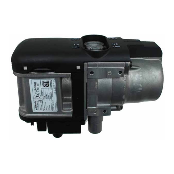
Water Heater
Thermo Top Evo Parking Heater
Installation documentation
Skoda Roomster
Validity
Manufacturer
Skoda
Motorisation
Fuel
1.2 TDI
Diesel
1.6 TDI
Diesel
SG = manual transmission
From Model Year 2010
Left-hand drive vehicle
Only in case of battery up to
61 Ah!
Verified equipment vari-
ants:
Not verified:
Total installation time:
Ident. No.: 1316415C_EN
00 0258
Model
Roomster
Transmission type Output in kW
SG
SG
Manual / automatic air-conditioning system
Front fog light with daytime running light
Cornering dipped headlights
Passenger compartment monitoring
Automatic transmission
Headlight washer system
approx. 8 hours
Status: 19.09.2012
e1
Type
EG-BE No./ ABE
5J
e11 * 2001 / 116 * 0291 * ...
Displacement in
cm³
55
1199
66
1598
Feel the Drive
Engine code
CFWA
CAYB
© Thermo&Comfort SE
Advertisement
Table of Contents

Related Manuals for Webasto Thermo Top Evo


Summary of Contents for Webasto Thermo Top Evo
-
Page 1: Validity
Water Heater Feel the Drive Thermo Top Evo Parking Heater 00 0258 Installation documentation Skoda Roomster Validity Manufacturer Model Type EG-BE No./ ABE Skoda Roomster e11 * 2001 / 116 * 0291 * ... Motorisation Fuel Transmission type Output in kW... -
Page 2: Table Of Contents
Fan Controller for Automatic Air-Conditioning Digital Timer Remote Option (Telestart) Necessary Components • Basic delivery scope Thermo Top Evo in accordance with price list • Installation kit for Skoda Roomster 2010 Diesel 1316414A • Additionally with automatic air-conditioning Automatic A/C kit 1316442B •... -
Page 3: Information On Operating And Installation Instructions
Installation and repair may ONLY be carried out by persons trained and VEHICLE INSTALLATION REQUIREMENTS certified in a Webasto training course. NEVER try to install or repair We- 2.1. Scope basto heating or cooling systems if you have not completed a Webasto training course, you do not have the necessary technical skills and you 2.1.1. -
Page 4: Information On Validity
• Crimping pliers for cable lug / tab connector 0.5 - 6mm² • Torque wrench for 2.0 - 10 Nm • Hose clamping pliers • Webasto Thermo Test Diagnosis with current software Dimensions • All dimensions are in mm Tightening torque values •... -
Page 5: Preliminary Work
Skoda Roomster Preliminary Work Vehicle • Open the fuel tank cap. • Ventilate the fuel tank. • Close the fuel tank cap again. • Depressurise the cooling system. • Completely remove the battery. • Remove the battery carrier. • Remove the windscreen wiper. •... -
Page 6: Preparing Electrical System
Skoda Roomster Preparing Electrical System rt/sw gn/ws Manual air-conditioning 0,5² 4² 0,75² K1 relay will be mounted later after installa- tion in vehicle. Insert red (rt) wire in the Preparing K1/87a relay socket and black (sw) wire fuse holder the K1/30 relay socket. -
Page 7: Electrical System
Skoda Roomster Electrical System Fuse holder Positive wire 1 M5x16 countersunk head screw, washer, 1 Positive wire on positive distributor of battery flanged nut, retaining plate for fuse holder 2 Positive distributor of battery 2 Remove relay for 5.5mm dia. hole Wiring har- Do not install the metering pump ness rout-... - Page 8 Skoda Roomster Place 5mm shim 1 as shown on carrier 2 of the central electrical box, copy hole pattern and drill 5.5mm dia. hole in central electrical box. When drilling holes, watch components and lines located behind them. In case of deviating routing of wiring harness 3, Installing it is to be routed below the fuse holder.
-
Page 9: Fan Controller For Manual Air-Conditioning
0,5² 2,5² 4² rt/sw gn/ws 0,5² 4² 0,75² 0,5² T4aa 0,5² 4² 0,5² Webasto components Vehicle components Colours and symbols Heater TT-Evo Fan motor 6-pin heater connector SB39 Fuse, 30A white 2-pin heater connector Resistor group black 4-pin connector Switch unit... -
Page 10: Fan Controller For Automatic Air-Conditioning
0,5² 4² 0,75² 0,35² IPCU T16d 0,5² J255 0,5² 0,5² 0,5² 4² 4² Webasto components Vehicle components Colours and symbols Heater TT-Evo J126 Fan unit 6-pin heater connector J255 A/C control panel white 2-pin heater connector SB39 Fuse, 30A black 4-pin connector T... -
Page 11: 1316415C_En
Skoda Roomster 1 Brown (br) wire from IPCU/85, 8mm dia. cable lug 2 Original vehicle bolt Earth con- nection IPCU Connection on central electrical box 5 to fan module. Produce connections as shown in wiring dia- gram. 1 Black/red (sw/rt) wire Connect- 2 Black (sw) wire from K1/30 ing fan mo-... -
Page 12: Digital Timer
Skoda Roomster Digital Timer 1 Digital timer Installing digital tim- Remote Option (Telestart) Install receiver 1 with double-sided adhesive tape as shown. Telestart 1 Antenna Installing antenna Temperature sensor T100 HTM Fasten temperature sensor 1 with adhesive tape. Installing tempera- ture sensor 1316415C_EN... -
Page 13: Preparing Installation Location
Skoda Roomster Preparing Installation Location Remove bracket of vacuum valve 1 and dis- card. The screw fitting will be reused later. Remove vacuum valve 2 from bracket 1 . De- tach earth cable 3 . Remove connector 4 with Preparing bracket, discard bracket 1 . - Page 14 Skoda Roomster 1 Vacuum valve 2 Flanged nut [2x] Preparing air cleaner housing Split provided insulation protection strip 1 in the middle and affix it. Fixing in- sulation protection Cut off wiring harness 2 as shown and insu- late wiring harnesses 3 and 4 . 1 18mm dia.
-
Page 15: Preparing Heater
Skoda Roomster Copy hole pattern 1 [2x] for 12mm dia. hole. Remove bracket. 1 7mm dia. hole [2x] Copying hole pat- tern When drilling, watch components located be- hind. Provide all holes with corrosion protec- tion. 1 Drill out 7mm dia. hole to 12mm dia. [2x] Hole in body Preparing Heater... -
Page 16: Installing Heater
Skoda Roomster Mould exhaust pipe 1 as shown. 2 Angle bracket 3 M6x20 bolt, p-clamp, flanged nut 4 Hose clamp Premount- ing exhaust pipe 1 5x13 self-tapping bolt [3x] 2 Bracket Installing bracket Installing Heater 1 M6x20 bolt, large diameter washer, flang- ed nut Installing heater... -
Page 17: Fuel
Skoda Roomster Fuel CAUTION! Open the vehicle's fuel tank cap, ventilate the tank and then re-close the tank lock. Catch any fuel running off with an appropriate container. Install fuel line and metering pump wiring harness so that they are protected against stone impact. Un- less specified otherwise, always fasten using cable ties. - Page 18 Skoda Roomster 1 Fuel line, metering pump wiring harness 2 Protective rubber plug Installing lines 1 Fuel line, metering pump wiring harness Installing lines Route fuel line together with metering pump wiring harness into corrugated tube 1 through original vehicle line duct to underbody. Installing lines 1 Fuel line, metering pump wiring harness...
- Page 19 Skoda Roomster Bend perforated bracket 1 as shown. 2 Drill hole to 8.5mm dia. Preparing perforated bracket 80° 1 Original vehicle bolt 2 Perforated bracket Installing perforated bracket Ensure sufficient distance to neighbouring components. 1 M6x25 bolt, support angle, flanged nut 2 Metering pump mount Installing metering...
- Page 20 Skoda Roomster 1.2 TDI Remove fuel-tank sending unit 3 in accord- ance with manufacturer's instructions. Place washer 1 outer dia. = 17.6mm centrally be- tween the connection pieces. Fuel ex- traction 2 Copy hole pattern, 6 mm dia. hole Shape fuel standpipe 1 according to tem- plate, cut to length and install.
- Page 21 Skoda Roomster Shape fuel standpipe 1 according to tem- plate, cut to length and install. Installing fuel stand- pipe Install fuel-tank sending unit 1 in accordance with manufacturer's instructions. 2 Hose section, 10 mm dia. clamp [2x] 3 Fuel line 4 Fuel standpipe Fuel ex- traction...
-
Page 22: Coolant Circuit
Skoda Roomster Coolant Circuit WARNING! Any coolant running off should be collected using an appropriate container. Install hoses so that they are kink-free. Unless specified otherwise, always fasten using cable ties. Position clamps so that no other hose can be damaged! When installing the hoses, the heater must be filled with coolant. The connection should be "inline"... - Page 23 Skoda Roomster Discard section X . Hose C = 90°, 18x18mm moulded hose Cutting hoses to length 1 Remove engine outlet hose section 2 Spring clip will be reused. Cutting point Remove hose section 2 from quick release coupling 1 of heat exchanger inlet, spring clip 3 will be reused.
- Page 24 Skoda Roomster 1 M6x20 bolt, flanged nut 2 29 mm dia. rubber-coated p-clamp 3 Circulating pump 4 48 mm dia. rubber-coated p-clamp 5 Perforated bracket Premount- ing circu- lating pump Watch flow direction of circulating pump 2 . 1 Black (sw) rubber isolator [2x] 3 Connection of engine outlet Premount- ing hoses...
- Page 25 Skoda Roomster 1 Original vehicle flanged nut 2 Premounted circulating pump 3 Mount wiring harness of circulating pump Installation of hose group Connect- ing heater Check the position of the components; adjust if necessary. Check that they have freedom of movement.
- Page 26 Skoda Roomster Check the position of the components; adjust if necessary. Check that they have freedom of movement. 1 Connection piece of heat exchanger inlet 2 Original vehicle hose of hose group Connec- tion of heat exchanger inlet 1316415C_EN...
-
Page 27: Combustion Air
Skoda Roomster Combustion Air When drilling, watch components located be- hind. Provide hole with corrosion protection. 1 6.5mm dia. hole Hole for si- lencer 1 Combustion air pipe 2 25 mm dia. spring clip Installing combus- tion air pipe 1 Combustion air pipe 2 Silencer 3 52mm dia. -
Page 28: Exhaust Gas
Skoda Roomster Exhaust Gas 1 Angle bracket Angling an- gle bracket 110° 1 Silencer 2 M6x16 bolt, spring lockwasher, large diam- eter washer 3 Angle bracket Preparing silencer Check the position of the components; adjust if necessary. Check that they have freedom of movement. - Page 29 Skoda Roomster 1 Exhaust pipe 2 Hose clamp 3 Silencer Installing exhaust pipe 1 Perforated bracket Angling down per- forated bracket 90° Mould end section 1 as shown. 2 P-clamp 3 Flanged nut as spacer 4 M6x20 bolt, flanged nut 5 Perforated bracket Premount- ing end...
- Page 30 Skoda Roomster 1 Wheel well trim 2 Drill 55mm dia. hole Preparing wheel well trim Check the position of the components; adjust if necessary. Check that they have freedom of movement. Align exhaust end section 1 to hole 2 in the in- stalled wheel well trim.
-
Page 31: Final Work
Skoda Roomster Final Work Install provided retaining clamp 2 and mount Bowden cable 1 of the engine bonnet lock. Installing retaining clamp Ensure freedom of movement of hoses 1 . 2 Vacuum valve Aligning hoses Remove mounting of engine bonnet bracket 1 and reinstall as shown. - Page 32 - Place instruction signboard "Switch off parking heater before refuelling“ in the area of the filler neck. - For initial start-up and function test, refer to installation instructions. Feel the Drive Webasto Thermo & Comfort SE Postfach 1410 82199 Gilching Germany Internet: www.webasto.com...
-
Page 33: Template For Fuel Standpipe
Skoda Roomster Template for Fuel Standpipe 100mm Scale 1:1 Compare the size of the printed version with dimension lines. Permitted tolerance a maximum of 2%. Set the printer settings to “no margin” or “minimise margins” and 100% of the normal size. 100mm 1316415C_EN... -
Page 34: Operating Instructions For Manual Air-Conditioning
Skoda Roomster Feel the Drive Operating Instructions for Manual Air-Conditioning Please remove this page in case of manual air-conditioning and add it to the vehicle operating instructions. Note: We recommend matching the heating time to the driving time. Heating time = driving time Example: For a driving time of approx. -
Page 35: Operating Instructions For Automatic Air-Conditioning
Skoda Roomster Feel the Drive Operating Instructions for Automatic Air-Conditioning Please remove this page in case of automatic air-conditioning and add it to the vehicle operating instructions. Note: We recommend matching the heating time to the driving time. Heating time = driving time Example: For a driving time of approx.
Need help?
Do you have a question about the Thermo Top Evo and is the answer not in the manual?
Questions and answers