
Subscribe to Our Youtube Channel
Related Manuals for Sunrise Medical Whitmyer


Summary of Contents for Sunrise Medical Whitmyer
- Page 1 Directions for use Notice d’utilisation Whitmyer Gebruikershandleiding www.sunrisemedical.com | 1 Head Support Instructions www.jay-seating.com...
- Page 2 www.sunrisemedical.com | 2 Head Support Instructions www.jay-seating.com...
-
Page 3: Table Of Contents
Strap Cap Installation instructions Dynamic Anterior Support | Dfs 2 HEDZ-UP Static Forehead Strap Instructions Cuddles Anterior Supports Cuddles Lateral Supports T-Bar Installation Instructions Unibar Installation Instructions Product Warranty Whitmyer Biomechanix Product Maintenance www.sunrisemedical.com | 1 Head Support Instructions www.jay-seating.com... -
Page 4: General Receiving / Assembly Instructions
General Receiving / Assembly Instructions Compare items received to enclosed packing slip. All items are individually bagged and labled for ease of identification. Note: The individual parts making up kits will appear below the kit part number as indented line items. Example: Kit Part Number = [PRO-1L] 4” x 6” occ w/size 1 subpads w/L cvrs on PRO mounting system Kit Comprises of: PSO1LL pad, size 1 LEFT sub-occ/Lycra... -
Page 5: Detachable Mounting Brackets
Detachable Mounting Brackets LIGHTWEIGHT M8000 2” Mounting hardware options: Recommended mount- ing height to top of T-nuts or nylock nuts w/washers. chair back is: 2" Mounting hole spacing options: 2 hole = 1 " or 2" ” NOTE: Circled letters act as a reference point when ordering replacement parts from Customer Service (800) 944-8246 Detachable Mounting Bracket LINX-M2300 PRO-M2200... -
Page 6: Custom Mounting Options
2 hole = 1” or 2” 4 hole = 1” x 2” Note: Old style hardware kit included for mounting older style Whitmyer Biomechanix detach and swingaway mounts. NOTE: Circled letters act as a reference point when ordering replacement parts from Customer... -
Page 7: Custom Mounting Options
Custom Mounting Options Detachable Mount to Quick Mount M7000 Mounting hole spacing options: 2 hole = 1” and 2” 24” 12” NOTE: Mounting clamps & plate have full adjustability. www.sunrisemedical.com | 5 Head Support Instructions www.jay-seating.com... -
Page 8: Axys Mounting System
AXYS Mounting System Assembly 1. Assemble as shown in Fig. 1. 2. See pages for pad and accessory attachment: Pad(s)- page 11, Anterior Supports – page 13, 18-19, Base plate assembly – page 12, Lateral Supports – page 14-16 Adjustments 1. -
Page 9: Linx Mounting System
Linx Mounting System 1. Assemble and position as shown in Fig.1. Index pin on anti-rotational collar (Fig.1,C) fits in to slot in top of detach receptacle (Fig.1, D) to prevent rotation. 2. See pages for pad and accessory attachment / adjustments: Pad(s)- page 13 Anterior Supports – page 15, 20-21 Base plate assembly – page 14 Lateral Supports – page 16-18 Adjustments 1. -
Page 10: Cobra Xtra Flip Back Mounting System
COBRA XTRA Flip Back Mounting System Assembly 1. Assemble as shown in Fig. 1. 2. See pages for pad and accessory attachment: Pad(s)- page 11, Anterior Supports – page 13, 18-19, Base plate assembly – page 12, Lateral Supports – page 14-16 Adjustments 1. -
Page 11: Pro Mounting System
Pro Mounting System 1. Unsnap horizontal pivot cover (Fig. 2, B). Angle T-handle or ball driver beneath tab and push up and outward. Refer to Fig. 1. Index pin on anti-rotational collar (Fig. 1, C) fits in to slot in top of detach receptacle (Fig. 1, D) to prevent rotation. 2. See pages for pad and accessory attachment / adjustments: Pad(s)- page 13 Anterior Supports –... -
Page 12: Working With Balls & Collars
Working With Balls & Collars All Whitmyer Biomechanix rotational mounting balls are manufactured with a machined knurl pattern. When the collar is tightened, the specialized hardened knurls bite into the radius to eliminate unwanted movement. Knurled pattern Fig. 1 Knurled pattern locks surfaces of ball Fig. -
Page 13: Base Plate Assembly Attachment
Base Plate Assembly Attachment 3-Pad Base Plate Assembly Attachment (Fig. 1) 1. Remove vinyl cover (E) from collar (A). Slide over horizontal ball (C). 2. Loosen rotational bracket (A) collar bolts (B). 3. Clamp mounting system horizontal ball (C) between the rotational bracket collar halves (A). Even though the knurled balls eliminate unwanted pad movement, the collars must be evenly tightened to reach their full locking strength. -
Page 14: Anterior Support Attachment
Anterior Support Attachment Anterior Support Attachment to Single Pad Interface 1. Remove bolts (Fig. 1, A) and discard bottom collar half (Fig. 1, B) of pad. 2. Evenly clamp the horizontal ball (Fig. 1, C) between the pad collar half (Fig. 1, D) and anterior support interface (Fig. -
Page 15: Contoured Cradle Lateral Support Option
Contoured Cradle Lateral Support Option 1. Attach swingaway lateral bracket(s) (Fig. 1, D) to Contoured Cradle lateral support interface plate (Fig. 1, C) using bolts (Fig. 1, A) and washers (Fig. 1, B). 2. Refer to Fig. 3. Tighten bolts (Fig. 3, A) securely. Swingaway lateral bracket may be bolted either left or right or used in unilateral or bilateral configurations. -
Page 16: Plush Lateral Support Option
PLUSH Lateral Support Option 1. Attach swingaway lateral bracket(s) (Fig. 1, D) to PLUSH lateral support interface plate (Fig. 1, C) using bolts (Fig. 1, A) and washers (Fig. 1, B). 2. Refer to Fig. 3. Tighten bolts (Fig. 3, A) securely. The PLUSH lateral support interface plate supplies 4 lateral mount locations. -
Page 17: S.o.f.t. Lateral Support Option
S.O.F.T. Lateral Support Option 1. Attach swingaway lateral bracket(s) (Fig. 1, D) to S.O.F.T. base plate assembly (Fig. 1, C) using bolts (Fig. 1, A) and washers (Fig. 1, B). Tighten bolts securely. 2. Refer to Fig. 2. Loosen bolts (Fig. 2, A) and clamp splitball (Fig. 2, B) between the lateral mount collar halves (Fig. 2, C) and tighten. Do not securely tighten collar halves until fitting to client to allow for adjustment of ballrod. -
Page 18: Lateral Facial Pad Positioning
Lateral Facial Pad Positioning Lateral Facial Components (LFC’s) are designed to assist in supporting the head laterally to help your client maintain a vertical alignment when lateral deviation is present or for low-profile switch access. Use a bilateral configuration to inhibit Asymmetrical tonic neck reflex (ATNR) by placing the pads in a position that will counteract the rotation that is occurring. Carefully place the pad(s) in a position that will evenly distribute the pressure placed upon them to avoid discomfort. -
Page 19: Contoured Cradle Anterior And Lateral Support Combination
Contoured Cradle Anterior and Lateral Support Combination 1. Unbolt bottom collar adapters (Fig. 1, A) from interface plates (Fig. 1,B) and (Fig. 1,C) as shown in Fig. 2. 2. Discard ONE bottom collar adapter (Fig. 2, A). 3. Refer to Fig. 3. Bolt together parts (Fig. 3, A), (Fig. 3, B) and (Fig. 3, C) using bolts (Fig. 3, D) and washers (Fig. 3, E) being sure to fit them together in the order shown. Tighten securely. -
Page 20: Plush Anterior And Lateral Support Combination
PLUSH Anterior and Lateral Support Combination 1. Unbolt bottom collar adapters (Fig. 1, A) from interface plates (Fig. 1,B) and (Fig. 1,C) as shown in Fig. 2. 2. Discard ONE bottom collar adapter (Fig. 2, A). 3. Refer to Fig. 3. Bolt together parts (Fig. 3, A), (Fig. 3, B) and (Fig. 3, C) using bolts (Fig. 3, D) and washers (Fig. 3, E) being sure to fit them together in the order shown. Tighten securely. -
Page 21: Contoured Cradle Systems
Contoured Cradle Systems Contoured Cradle pads are designed to provide lateral cervical and sub-occipital support in a single pad. The pad should be adjusted to provide even contact across its surface and allow the flared tips to support the cervical spine just under the ears and behind the mastoid process. Gently bend flared sections in to place by hand to accommodate various neck widths. PLUSH Systems Plush pads are designed to provide comfortable support to the upper cervical and sub- occipital areas. -
Page 22: Single Sub-Occipital Systems
Single Sub-occipital Systems The Single Sub-occipital systems are designed to provide lateral cervical support with an independently adjustable occipital pad for posterior support. 1. Adjust the height and depth of the mounting system to place the head support in the general position of the sub-occipital and occipital regions of the head. 2. ( Fig. 3) Adjust the sub-occipital pad (B) first. Moving the occipital pad (A) completely rearward makes this easier. -
Page 23: S.o.f.t. (Multi-Pad) Systems
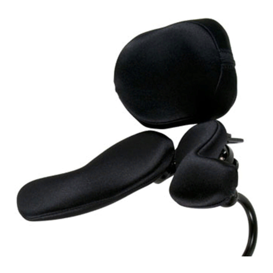
S.O.F.T. (Multi-Pad) Systems S.O.F.T. Three Pad systems are completely adjustable and provide maximum lateral cervical and occipital support. 1. Simulation (Fig. 1): While holding the client’s head with your hands in the desired position, observe the amount of balance, types of movement and effects of pathological reflex activity. Tip: A digital picture at this point could be very helpful during the final adjustment. Remember: All S.O.F.T. configurations universally fit the ONYX, LINX, or PRO mounting systems. Pictures show a PRO mounting system with a S.O.F.T. three pad configuration. -
Page 24: Adjusting The System To The User
Adjusting the system to the user The width between the sub-occipital pads can be adjusted to the width of the neck by sliding the screwballs laterally in their slots. (Page 22, Fig. 2, B). Pads should be adjusted so that even contact is made and primary support is provided on the rear of the pads (Fig. -
Page 25: Dynamic Forehead Strap System
Dynamic Forehead Strap System Patent Number 5,306,232 CAUTION! Read and understand all instructions prior to fitting or using the Dynamic Forehead Strap System. The Dynamic Forehead Strap System (DFS) provides anterior forehead support that moves with the user. The DFS must be applied and used under therapist or rehab seating professional supervision. -
Page 26: Dynamic Forehead Strap Components
Dynamic Forehead Strap components >>> WARNING! CHOKING HAZARD Improper use of this device may result in serious injury or death. • Use with supervision. • R ead and understand all instructions and safety labels. • D o not over tighten - Strap should not be tight enough to cause redness, irritation or excessive pressure. • T he strap should not be loose enough to allow the strap to slip over the eyes and nose. -
Page 27: Dynamic Forehead Strap Adjustment
Dynamic Forehead Strap Adjustment READ AND UNDERSTAND ALL INSTRUCTIONS AND WARNINGS BEFORE ADJUSTING THE DFS TO THE USER. STEP 1 - Putting on the strap: With the client in the chair, ensure the head support system is correctly installed (refer to the previous sections on system installation). -
Page 28: Strap Cap Installation Instructions
Dynamic Forehead Strap with strap cap option Foam Insert Pouch Tension Adjuster (Cut-Away View) Pulley Mechanism Strap Warning Label Forehead Strap Cord Tension Adjuster The Strap Cap is compatible with all Whitmyer Biomechanix, Dynamic Forehead Strap systems. 26 | Head Support Instructions www.jay-seating.com www.sunrisemedical.com... - Page 29 DYNAMIC ANTERIOR SUPPORT | DFS 2 User instructions for models DFSQ1, DFSQ3, DFSQ10 and DFSQ30 Patent Pending WARNING ! READ THIS BEFORE USE Read warnings and instructions often until they are second nature. Keep this guide with the product for further reference. If you have any questions on the assembly and installation of this product please contact the A.R.T.
-
Page 30: Dynamic Anterior Support | Dfs 2
DYNAMIC ANTERIOR SUPPORT | DFS 2 >>> Installation: Re-Tighten guide rod adjustment screw (F) to hold position. Using a e/ah” Allen ® wrench: Loosen the rear occipital screwball Guide rods may be trimmed to 1” limiting Fig-1 (A), adjust up or down to provide slot rearward protrusion. -
Page 31: Hedz-Up Static Forehead Strap Instructions
HEDZ-UP Static Forehead Strap Instructions CAUTION! Consult with a qualified therapist or rehab technology supplier trained in postural positioning before installing or adjusting this product. Read and understand all instructions and warnings before using the product. We are available to answer questions 8:00 a.m. to 5:00 p.m. Eastern Standard Time. Please call us at 800-944-8246. Installation: Using a 3/16” Allen® wrench: 1. Loosen the rear occipital screwball (A), adjust up or down to provide slot access. -
Page 32: Cuddles Anterior Supports
Cuddles Anterior Supports Application Consideration WARNING! • Use only when child can be monitored. • Anterior strap should not be used with children who may grab or pull the support strap. • Only for use for children under 3 years of age. •... -
Page 33: T-Bar Installation Instructions
T-Bar Installation Instructions Systems ordered with T-bar occipital mounts will arrive with the T-bar attached to the occipital mount. These instructions are for retro-fitting an existing system Fig.2 Fig.1 Using a 3/16” Allen® wrench: 1. Remove the occipital pad and screwball (Fig.1, A) from the occipital plate (Fig.1, B). 2. -
Page 34: Product Warranty
For warranty service, please contact our Customer Service Department for a Return Authorization Number. Please be prepared to provide the purchase information and the nature of the defect. Do not return products to Whitmyer Biomechanix without our prior approval. Limitations and Exclusions: The foregoing warranty shall not apply to damage... -
Page 35: Sommaire
SUPPORT ANTÉRIEUR DYNAMIQUE | DFS 2 Instructions pour la sangle frontale statique HEDZ-UP Supports antérieurs Cuddles Supports latéraux Cuddles Instructions d'installation de la barre en T Instructions d'installation de l'Unibar Garantie du produit Entretien des produits Whitmyer Biomechanix Avis www.sunrisemedical.com | 33 Head Support Instructions www.jay-seating.com... -
Page 36: Instructions Générales D'assemblage / De Réception
Instructions générales d'assemblage / de réception Comparez les articles reçus à la liste jointe des articles. Tous les articles sont emballés et étiquetés individuellement pour faciliter l'identification. Remarque : Les pièces individuelles faisant partie des kits apparaîtront sous le numéro de pièce du kit sous forme de liste d'articles. Exemple : Référence du kit = [PRO-1L] 4”... -
Page 37: Supports De Fixation Détachables
Supports de fixation détachables LIGHTWEIGHT M8000 La hauteur de fixation 2” Options de matériel de recommandée fixation : jusqu'en haut du dossier du fauteuil Écrous encastrés ou nylock avec est : 50 mm rondelles. Options d'espacement des trous de fixation : ” 2 trous = 48 mm ou 50 mm REMARQUE : Les lettres encerclées servent de référence lors de la commande de pièces de rechange auprès du service clientèle au +33 (0) 2 47 55 44 00 Support de fixation détachable... -
Page 38: Options De Fixation Personnalisée
Whitmyer Biomechanix. REMARQUE : Les lettres encerclées servent de référence lors de la commande de pièces de rechange auprès du service clientèle au +33 (0) 2 47 55 44 00 36 | Head Support Instructions www.jay-seating.com... -
Page 39: Options De Fixation Personnalisée
Options de fixation personnalisée Système de montage et démontage rapide M7000 Options d'espacement des trous de fixation : 2 trous = 1” et 2” 24” 12” Remarque : Les pinces et la plaque de fixation sont entièrement réglables. www.sunrisemedical.com | 37 Head Support Instructions www.jay-seating.com... -
Page 40: Système De Fixation Axys
Système de fixation AXYS Assemblage 1. Assemblez comme indiqué sur la figure. 1. 2. V oir les pages pour la fixation de(s) coussinet(s) et accessoire(s) : Coussinet(s)- page 11, Supports antérieurs – page 13, 18-19, Assemblage du plateau inférieur – page 12, Supports latéraux – page 14-16 Réglages 1. Vertical - Desserrez la manette de levier (Fig. 1, E) et réglez à... -
Page 41: Système De Fixation Linx
Système de fixation Linx 1. Assemblez et positionnez comme indiqué en figure 1. Le doigt d'indexage sur le collet anti-pivotement (Fig. 1, C) s'engage dans la fente en haut du récepteur amovible (Fig. 1, D) pour empêcher le pivotement. 2. Voir les pages sur le réglage / la fixation des coussinets et accessoires : Coussinet(s)- page 13 Supports antérieurs – page 15, 20-21 Assemblage du plateau inférieur – page 14 Supports latéraux –... -
Page 42: Système De Fixation Renversé Cobra Xtra
Système de fixation renversé COBRA XTRA Assemblage 1. Assemblez comme indiqué sur la figure. 1. 2. V oir les pages pour la fixation de(s) coussinet(s) et accessoire(s) : Coussinet(s)- page 11, Supports antérieurs – page 13, 18-19, Assemblage du plateau inférieur – page 12, Supports latéraux – page 14-16 Réglages 1. Vertical - Desserrez la manette de levier (Fig. 1, D) et réglez à la hauteur appropriée puis abaissez le collet de butée (Fig. -
Page 43: Système De Fixation Pro
Système de fixation Pro 1. Dégagez le capuchon du pivot horizontal (Fig. 2, B). Placez la poignée en T ou le tournevis sous le capuchon et poussez vers le haut et l'extérieur. Voir Fig. 1. Le doigt d'indexage sur le collet anti-pivotement (Fig. 1, C) s'engage dans la fente en haut du récepteur amovible (Fig. -
Page 44: Utilisation Des Rotules Et Collets
Utilisation des rotules et collets Toutes les rotules de pivotement Whitmyer Biomechanix sont fabriquées avec une configuration moletée à la machine. Lorsque le collet est serré, les moletages durs spécialisés pénètrent dans le radius pour éliminer tout mouvement non désiré. Configuration moletée Fig. 1 La configuration moletée verrouille les Fig. 3 surfaces de la rotule et du collet. • (Fig. 1,3) Les rotules moletées pénètrent dans le radius pour éliminer tout mouvement non désiré. • (Fig. 2A, 2B) Bien que les rotules moletées éliminent les mouvements non désirés des coussinets, les collets doivent être serrés avec la même tension pour atteindre leur force de serrage... -
Page 45: Installation De L'ensemble Plateau Inférieur
Installation de l'ensemble plateau inférieur Installation de l'ensemble plateau inférieur à 3 coussinets (Fig. 1) 1. Retirez le capuchon en vinyle (E) du collet (A). Faites passer par dessus la rotule horizontale (C). 2. Desserrez les boulons du collet (B) du support pivotant. 3. I nstallez la rotule horizontale du système de fixation (C) entre les deux moitiés du collet du support pivotant (A). Bien que les rotules moletées éliminent les mouvements non désirés des coussinets, les collets doivent être serrés avec la même tension pour atteindre leur force de serrage maximum. -
Page 46: Fixation Du Support Antérieur
Fixation du support antérieur Fixation d'un support antérieur à une interface de coussinet unique 1. Retirez les boulons (Fig. 1, A) et enlevez la moitié inférieure du collet (Fig. 1, B) du coussinet. 2. Installez la rotule horizontale bien au centre (Fig. 1, C) entre la moitié du collet du coussinet (Fig. 1, D) et l'interface du support antérieur (Fig. -
Page 47: Option De Support Latéral Pour L'appui-Tête Anatomique
Option de support latéral pour l'appui-tête anatomique 1. Fixez les supports latéraux escamotables (Fig. 1, D) à la plaque d'interface du support latéral de l'appui-tête anatomique (Fig. 1, C) en utilisant les boulons (Fig. 1, A) et les rondelles (Fig. 1, B). 2. Voir Fig. 3. Serrez bien les boulons (Fig. 3, A). Le support latéral escamotable peut être monté soit à gauche soit à droite ou utilisé en configurations unilatérale ou bilatérale. -
Page 48: Option De Support Latéral Plush
Option de support latéral PLUSH 1. Fixez les supports latéraux escamotables (Fig. 1, D) à la plaque d'interface du support latéral PLUSH (Fig. 1, C) en utilisant les boulons (Fig. 1, A) et les rondelles (Fig. 1, B). 2. V oir Fig. 3. Serrez bien les boulons (Fig. 3, A). La plaque d'interface du support latéral PLUSH offre 4 points d'attache latérale. 3. Voir Fig. 2. Retirez les boulons (Fig. 2, A) et enlevez la moitié inférieure du collet du coussinet (Fig. 2, 4. -
Page 49: Option De Support Latéral S.o.f
Option de support latéral S.O.F.T. 1. Fixez les supports latéraux escamotables (Fig. 1, D) à l'ensemble de la base inférieure S.O.F.T. (Fig. 1, C) en utilisant les boulons (Fig. 1, A) et les rondelles (Fig. 1, B). Serrez bien les boulons. 2. -
Page 50: Positionnement Du Coussinet Latéro-Facial
Positionnement du coussinet latéro-facial Les composants latéro-faciaux (CLF) sont conçus pour aider à soutenir la tête latéralement afin d'aider votre client à maintenir un alignement vertical lorsqu'il existe une déviation latérale ou pour accéder aux fonctions surbaissées d'un manipulateur. Utilisez une configuration bilatérale pour entraver le réflexe tonique assymétrique du cou (ATNR) en plaçant les coussinets dans une position qui neutralisera la rotation qui se produit. Placez avec soin le(s) coussinet(s) dans une position qui distribuera de façon homogène la pression placée sur eux afin d'éviter toute gêne. Familiarisez vous avec les différentes instructions de réglage : A. Réglage linéaire B. Réglage de la hauteur C. Réglage du pivotement AVERTISSEMENT ! Évitez de placer le(s) coussinet(s) directement sur le maxiliaire, les oreilles ou dans une région qui entrera en contact avec les yeux de l'utilisateur ! Si des irritations se produisent, interrompez immédiatement l'utilisation et contactez le thérapeute ou un spécialiste de technologie de rééducation. -
Page 51: Combinaison De Soutien Latéral Et Antérieur De L'appui-Tête Anatomique
Combinaison de soutien latéral et antérieur de l'appui-tête anatomique 1. Déboulonnez les adaptateurs du collet du bas (Fig. 1, A) des plaques de l'interface (Fig. 1,B) et (Fig. 1,C) comme indiqué en Fig. 2. 2. Retirez UN adaptateur du bas du collet (Fig. 2, A). 3. Voir Fig. 3. Revissez les pièces ensemble (Fig. 3, A), (Fig. 3, B) et (Fig. 3, C) en utilisant les boulons (Fig. 3, D) et les rondelles (Fig. 3, E) et assurez-vous de bien les réassembler dans l'ordre indiqué. Resserrez bien. -
Page 52: Combinaison De Soutien Latéral Et Antérieur Plush
Combinaison de soutien latéral et antérieur PLUSH 1. Déboulonnez les adaptateurs du collet du bas (Fig. 1, A) des plaques de l'interface (Fig. 1,B) et (Fig. 1,C) comme indiqué en Fig. 2. 2. Retirez UN adaptateur du bas du collet (Fig. 2, A). 3. Voir Fig. 3. Revissez les pièces ensemble (Fig. 3, A), (Fig. 3, B) et (Fig. 3, C) en utilisant les boulons (Fig. 3, D) et les rondelles (Fig. 3, E) et assurez-vous de bien les réassembler dans l'ordre indiqué. -
Page 53: Systèmes D'appui-Tête Anatomique
Systèmes d'appui-tête anatomique Les coussinets de l'appui-tête anatomique sont conçus pour offrir un soutien sous- occipital et latéral avec un seul coussinet. Le coussinet doit être réglé de façon à offrir un contact homogène sur toute sa surface et permettre aux pointes évasées de soutenir la colonne cervicale juste en dessous des oreilles et derrière l'apophyse mastoïde. Pliez gentiment à la main les sections évasées pour adapter aux diverses largeurs de nuque. -
Page 54: Systèmes Sous-Occipitaux Simples
Systèmes sous-occipitaux simples Les systèmes sous-occipitaux simples sont conçus pour offrir un soutien cervical latéral avec un coussinet occipital réglable indépendamment pour un soutien postérieur. 1. Réglez la hauteur et la profondeur du système de fixation pour placer le support de la tête dans la position générale des régions occipitales et sous- occipitales de la tête. -
Page 55: Systèmes (Multi-Coussinets) S.o.f
Systèmes (multi-coussinets) S.O.F.T. S.O.F.T. Les systèmes à trois coussinets sont complètement réglables et offrent un soutien occipital et cervical latéral maximum. 1. Simulation (Fig. 1) : Tout en conservant la tête du client dans vos mains dans la position désirée, observez l'aplomb, les types de mouvement et les effets de l'activité de réflexe pathologique. -
Page 56: Réglage Du Système En Fonction De L'utilisateur
Réglage du système en fonction de l'utilisateur La largeur entre les coussinets sous-occipitaux peut être réglée sur la largeur de la nuque en faisant glisser les rotules d'attache latéralement dans leurs cavités. (Page 22, Fig. 2, B). Les coussinets doivent être réglés de façon à ce que le contact soit homogène et que le support principal soit fourni sur l'arrière des coussinets (Fig. 4). 6. 2 ) Réglez le coussinet occipital suffisament vers l'avant pour venir en contact avec l'occiput. Desserrer les boulons (Page 22, Fig. 2, E) permet de déplacer le coussinet vers le haut ou vers le bas pour un contact optimal avec la tête. -
Page 57: Système De Sangle Frontale Dynamique
Système de sangle frontale dynamique Numéro de brevet 5 306 232 ATTENTION ! Lisez toutes les instructions avant d'installer et d'utiliser le système de sangle frontale dynamique. Le système de sangle frontale dynamique (SFD) fournit un soutien frontal antérieur qui bouge avec l'utilisateur. -
Page 58: Erreurs Fréquemment Commises Lors Du Réglage De La Sangle Frontale Dynamique
Composants de la sangle frontale dynamique >>> AVERTISSEMENT ! DANGER D'ÉTOUFFEMENT Une mauvaise utilisation de ce mécanisme peut entraîner de graves blessures ou s'avérer mortelle. • À utiliser sous surveillance. • Lire et comprendre toutes les étiquettes d'instructions et de sécurité. • Ne pas trop serrer - La sangle ne doit pas être serrée au point de provoquer des rougeurs, une irritation ou une pression excessive. -
Page 59: Réglage De La Sangle Frontale Dynamique
Réglage de la sangle frontale dynamique LIRE ET COMPRENDRE TOUTES LES INSTRUCTIONS ET AVERTISSEMENTS AVANT DE RÉGLER LA SFD POUR L'UTILISATEUR ÉTAPE 1- Installation de la sangle : Avec le client dans le fauteuil, assurez-vous que le système de l'appui- tête est correctement installé (voir les sections précédentes sur l'installation du système). -
Page 60: Instructions D'installation De La Casquette Strap Cap
Mécanisme de réglage de tension (Vision en coupe) Mécanisme de poulie Casquette Étiquette d'avertissement de la sangle frontale Corde Mécanisme de réglage de tension La casquette Strap Cap est compatible avec tous les systèmes de sangle frontale dynamique de Whitmyer Biomechanix. 58 | Head Support Instructions www.jay-seating.com www.sunrisemedical.com... - Page 61 SUPPORT ANTÉRIEUR DYNAMIQUE | DFS 2 Instructions d'utilisation pour les modèles DFSQ1, DFSQ3, DFSQ10 et DFSQ30 Demande de brevet déposée AVERTISSEMENT ! À LIRE AVANT UTILISATION Lisez les avertissements et instructions régulièrement jusqu'à ce qu'ils vous soient parfaitement familiers. Conservez ce guide avec le produit pour future référence. Si vous avez des questions sur l'assemblage et l'installation de ce produit, veuillez contacter le groupe A.R.T.
-
Page 62: Support Antérieur Dynamique | Dfs 2
SUPPORT ANTÉRIEUR DYNAMIQUE | DFS 2 >>> Installation : En utilisant une clé hexagonale e/ah” Allen ® : Resserrez la vis de serrage de la barre de guidage Desserrez la rotule d'attache occipitale arrière (F) pour conserver la position. Fig. 1 (A), déplacez vers le haut ou vers le bas pour Les barres de guidage peuvent être coupées de 1"... -
Page 63: Instructions Pour La Sangle Frontale Statique Hedz-Up
Instructions pour la sangle frontale statique HEDZ-UP ATTENTION ! Consultez un thérapeute qualifié ou un spécialiste en technologie de rééducation qualifié en positionnement de posture avant l'installation et le réglage de ce produit. Lisez et comprenez toutes les instructions et tous les avertissements avant d'utiliser le produit. Nous sommes disponibles pour répondre à vos questions de 8 heures à 17 heures. Heure d'hiver de New York (EST). Veuillez nous appeler au 800-944-8246. Installation : En utilisant une clé... -
Page 64: Supports Antérieurs Cuddles
Supports antérieurs Cuddles À prendre en considération pour l'application AVERTISSEMENT ! • Utilisez uniquement lorsque l'enfant est surveillé. • La sangle antérieure ne doit pas être utilisée avec des enfants qui peuvent attraper ou tirer la sangle de support. • À utiliser uniquement pour les enfants de moins de trois ans. • N'attachez ou ne modifiez pas pour l'utilisation avec des produits autres que Cuddles. • Inapproprié pour des enfants pouvant activement et fortement se fléchir. 1. -
Page 65: Instructions D'installation De La Barre En T
Instructions d'installation de la barre en T Les systèmes commandés avec des supports occipitaux en T arriveront avec la barre en T attachée au support occipital. Ces instructions sont pour la rétro installation d'un système existant Fig. 2 Fig. 1 A l’aide d’une clé... -
Page 66: Garantie Du Produit
Garantie du produit Whitmyer Biomechanix garantit tous les composants dans ses produits contre tout défaut matériel ou de fabrication pendant un an à partir de la date d'achat. Tous les composants métalliques ont une garantie à vie contre la casse. Toutes les protections, mousses, cordes, pièces en plastique et les angles ont une garantie de 90 jours. Si un produit s'avère défectueux, ce produit pourra être réparé ou remplacé selon l'option sélectionée par Whitmyer Biomechanix. Cette garantie n'inclut pas les frais de transport ou de main d'œuvre encourus pour l'installation des pièces de remplacement ou la réparation. L'unique obligation de Whitmyer Biomechainx et votre unique recours au... - Page 67 Montage-instructies voor Strap Cap DYNAMISCHE VOORWAARTSE ONDERSTEUNING | DFS 2 Instructies HEDZ-UP Statische voorhoofdband Cuddles voorwaartse ondersteuning Cuddles Laterale steunen Instructies voor bevestiging T-Bar Instructies voor bevestiging Unibar Garantie Whitmyer Biomechanix onderhoud van producten Kennisgeving www.sunrisemedical.com | 65 Head Support Instructions www.jay-seating.com...
-
Page 68: Algemene Instructies Voor Ontvangst/Montage
Algemene instructies voor ontvangst/montage Vergelijk de onderdelen die u hebt ontvangen met de bijgesloten pakbon. Alle onderdelen zijn individueel verpakt en hebben een sticker hierdoor zijn ze gemakkelijk te herkennen. Opmerking: de afzonderlijke onderdelen in de kit staan in een lijst rechts in de kantlijn. Bijvoorbeeld: Kit onderdeelnummer = [PRO-1L] 4”... -
Page 69: Afneembare Bevestigingsbeugels
Afneembare bevestigingsbeugels LICHTGEWICHT M8000 2” Opties Aanbevolen montage- bevestigingsmaterialen: hoogte aan de boven- zijde van rugleuning T-bouten en Nylock moeren m/ is: 2" ringen. Opties bevestigingsgaten: ” 2 gaten = 1 " of 2" OPMERKING: U kunt de omcirkelde letters als referentie gebruiken wanneer u vervangende onderdelen bestelt bij onze klantendienst (800) 944-8246. -
Page 70: Opties Bevestigingen Maatwerk
2 gaten = 1” of 2” 4 gaten = 1” x 2” Opmerking: oud type kit bijgesloten om oudere types Whitmyer Biomechanix afneembare en zwenkbare opties te bevestigen. OPMERKING: U kunt de omcirkelde letters als referentie gebruiken wanneer u vervangende onderdelen bestelt bij onze klantendienst (0044) (0)1384 446666. - Page 71 Opties bevestigingen maatwerk Afneembare bevestiging voor snelle M7000 bevestiging Opties bevestigingsgaten: 2 gaten = 1” en 2” 24” 12” OPMERKING: bevestigingsklemmen en plaat zijn volledig verstelbaar. www.sunrisemedical.com | 69 Head Support Instructions www.jay-seating.com...
-
Page 72: Axys Bevestigingssysteem
AXYS bevestigingssysteem Montage 1. Monteer onderdelen zoals getoond in afbeelding 1. 2. Zie voor bevestiging van kussens en accessoires: kussen(s): pagina 11; voorwaartse ondersteuning: pagina's 13, 18-19; montage basisplaat:pagina 12; laterale ondersteuning: pagina 14-16. Aanpassingen 1. V erticaal - Maak de hendel (fig. 1, E) los, stel op de juiste hoogte, en doe dan de borgring omlaag (fig. 1, C). De verticale stang kan worden gedraaid om extra aanpassing van de hoek van de opbouw van kussen/basisplaat te verkrijgen. -
Page 73: Linx Bevestigingssysteem
Linx bevestigingssysteem 1. Bevestig en plaats in positie zoals getoond in fig. 1. De index-pen op de anti-draai borgring (fig. 1, C) gaat in de gleuf op de bovenzijde van beugel (fig. 1 D) om draaiing te voorkomen. 2. Zie onderstaande pagina's voor bevestiging/aanpassing van kussen en accessoires: Kussen(s) - pagina 13 Voorwaartse ondersteuning – pagina's 15, 20-21 Opbouw basisplaat – pagina 14 Lateral Supports – pagina's 16-18 Aanpassingen 1. Verticaal - Maak de hendel (fig. 1, E) los, stel op de juiste hoogte, en doe dan de borgring omlaag (fig. 1, C) zorg ervoor dat de index-pen in de gleuf valt in de koppeling. (Fig. 1, F) De verticale stang kan worden gedraaid voor extra aanpassing van de hoek van de opbouw kussen/basisplaat. -
Page 74: Cobra Xtra Flip Back Bevestigingssysteem
COBRA XTRA Flip Back bevestigingssysteem Montage 1. Monteer onderdelen zoals getoond in afbeelding 1. 2. Zie voor bevestiging van kussens en accessoires: kussen(s): pagina 11; voorwaartse ondersteuning: pagina's 13, 18-19; montage basisplaat:pagina 12; laterale ondersteuning: pagina 14-16. Aanpassingen 1. V erticaal - Maak de hendel (fig. 1, D) los, stel op de juiste hoogte, en doe dan de borgring omlaag (fig 2, C). De verticale stang kan worden gedraaid om extra aanpassing van de hoek van de opbouw van kussen/basisplaat te... -
Page 75: Pro Mounting Systeem
Pro Mounting systeem 1. Verwijder dop van horizontale draaipunt (Fig. 2, B). Steek een schroevendraaier onder de cover en duw deze omhoog en naar buiten. Zie Fig. 1. Steek de pen in de antidraai-borgring (Fig. 1, C) in de gleuf aan bovenzijde van houder (Fig. 1, D) om draaien te voorkomen. 2. -
Page 76: Werken Met Ballen En Ringen
Werken met ballen en ringen Alle roterende montageballen Whitmyer Biomechanix worden uitgerust met een ribbelpatroon. Wanneer de ring wordt aangedraaid, zetten de speciaal geharde ribbels zich vast in de radius waardoor ongewenste beweging onmogelijk wordt gemaakt. Ribbelpatroon Fig. 1 Een ribbelpatroon zorgt ervoor dat de Fig. -
Page 77: Bevestiging Opbouw Van 3 Kussens En Basisplaat
Bevestiging opbouw van 3 kussens en basisplaat Bevestiging opbouw van 3 kussens en basisplaat (Fig. 1) 1. Verwijder de vinyl afsluitdop (E) van borgring (A). Laat hem over de horizontale bal glijden (C). 2. Maak de bouten (B) van de borgring (A) los. 3. -
Page 78: Bevestiging Voorwaartse Ondersteuning
Bevestiging voorwaartse ondersteuning Bevestiging voorwaartse ondersteuning aan interface enkel kussen 1. Verwijder de bouten (Fig. 1, A) en haal de onderste helft van de borgring (Fig. 1, B) van het kussen 2. Klem de horizontale bal gelijkmatig (Fig. 1, C) tussen de borgring van het kussen (Fig. 1, D) en de interface van de voorwaartse ondersteuning (Fig. -
Page 79: Gevormde Omvattende Laterale Steun
Gevormde omvattende laterale steun 1. Bevestig de zwenkbare laterale beugel(s) (Fig. 1, D) aan de interfaceplaat van de gevormde omvattende laterale steun (Fig. 1, C) door middel van bouten(Fig. 1, A) en ringen (Fig. 1, B). 2. Zie Fig. 3. Draai de bouten (Fig. 3, A) stevig aan. De zwenkbare laterale beugel kan met een bout aan de linker of rechterzijde worden bevestigd of gebruikt worden in unilaterale of bilateralre configuraties. -
Page 80: Plush Laterale Ondersteuningsoptie
PLUSH Laterale ondersteuningsoptie 1. Bevestig de zwenkbare laterale beugel(s) (Fig. 1, D) aan de interfaceplaat van de PLUSH laterale steun (Fig. 1, C) door middel van bouten(Fig. 1, A) en ringen (Fig. 1, B). 2. Zie Fig. 3. Draai de bouten (Fig. 3, A) stevig aan. De interfaceplaat van de PLUSH laterale steun biedt 4 laterale bevestigingsmogelijkheden. -
Page 81: S.o.f.t. Laterale Steunoptie
S.O.F.T. Laterale steunoptie 1. Bevestig de zwenkbare laterale beugel(s) (Fig. 1, D) aan S.O.F.T. basisplaat opbouw (Fig. 1, C) door middel van bouten(Fig. 1, A) en ringen (Fig. 1, B). Draai de bouten stevig aan. 2. Zie Fig. 2. Maak de bouten los, (Fig. 2, A) en klem de splitbal (Fig. 2, B) tussen de helften van de borgring van de laterale bevestiging (Fig. -
Page 82: Plaatsing Lateraal Gezichtskussen
Plaatsing lateraal gezichtskussen De laterale gezichtsondersteunende onderdelen (Lateral Facial Components, LFC’s) zijn ontwikkeld om het hoofd van de patiënt lateraal te ondersteunen, zodat het hoofd rechtop gehouden kan worden bij een laterale afwijking, of voor toegankelijkheid tot bediening. Gebruik een bilaterale configuratie om een asymmetrisch tonisch nekreflex (ATNR) tegen te gaan, door de kussens zodanig te plaatsen dat de optredende rotatie wordt tegengegaan. Plaats de kussen(s) zorgvuldig in een positie waardoor de druk gelijkmatig wordt verdeeld en de patiënt comfortabel zit. -
Page 83: Combinatie Van Gevormde Omvattende Voorwaartse Delen En Laterale Ondersteuning
Combinatie van gevormde omvattende voorwaartse delen en laterale ondersteuning. 1. Schroef de adapters aan de onderzijde van de borgring los (Fig. 1, A) van de interfaceplaat (Fig. 1, B) en (Fig. 1, C) zoals getoond in Fig. 2. 2. Maak EEN adapter helemaal los (Fig. 2, A). 3. -
Page 84: Combinatie Van Plush Voorwaartse En Laterale Ondersteuning
Combinatie van PLUSH voorwaartse en laterale ondersteuning 1. Schroef de adapters aan de onderzijde van de borgring los (Fig. 1, A) van de interfaceplaat (Fig. 1, B) en (Fig. 1, C) zoals getoond in Fig. 2. 2. Maak EEN adapter helemaal los (Fig. 2, A). 3. -
Page 85: Contourkussen-Systemen
Contourkussen-systemen Het contourkussen is ontwikkeld om met één kussen steun te bieden aan nekwervels en achterhoofd, en het onderste deel van het achterhoofd ondersteuning te geven. Het kussen moet zodanig worden aangepast dat het gelijkmatig contact heeft met hoofd en hals. De vleugels dienen de nekwervels vlak onder de oren en achter het processus mastoïdes te steunen. -
Page 86: Enkele Systemen Voor Ondersteuning Van De Onderzijde Van Het Achterhoofd
Enkele systemen voor ondersteuning van de onderzijde van het achterhoofd. De Single Sub-occipitale systemen zijn ontwikkeld om laterale steun te bieden aan het bovenste deel van de hals, met een onafhankelijk verstelbaar kussen voor ondersteuning van het achterhoofd. 1. Pas de hoogte en diepte van het bevestigingssysteem aan, om de hoofdsteun in de algemene positie te zetten van het achterhoofd en bovenste deel van de nek. -
Page 87: S.o.f.t. (Multi-Pad) Systemen
S.O.F.T. (Multi-Pad) Systemen. S.O.F.T. De 3-kussen systemen zijn volledig verstelbaar en geven maximale laterale ondersteuning van het hoofd, en achterhoofd. 1. S imulatie (Fig. 1): Bekijk de balans, soorten beweging, en effecten van pathologische reflexen, terwijl u het hoofd van de gebruiker in uw handen houdt, in de gewenste positie. Tip: op dit moment kan een digitale foto uitstekend helpen om de laatste aanpassingen te doen. Onthoud: Alle S.O.F.T. configuraties passen universeel op de ONYX, LINX, of PRO bevestigingssystemen. Op de foto's wordt een PRO bevestigingssysteem getoond met een S.O.F.T. 3-kussen configuratie. -
Page 88: Aanpassing Van Het Systeem Aan De Gebruiker
Aanpassing van het systeem aan de gebruiker De vleugels moeten tot onder de oren en het processus mastoïdes doorlopen. (Fig. 4) Draai de moeren stevig vast. De breedte tussen de kussens ter ondersteuning van het achterhoofd kan worden aangepast aan de breedte van de nek, door de draaiballen zijwaarts in de gleuven te laten glijden. -
Page 89: Systeem Voor Dynamische Voorhoofdbanden (Dynamic Forehead Strap System, Dfs)
Systeem voor dynamische voorhoofdbanden (Dynamic Forehead Strap System, DFS) Patentnummer 5.306.232 OPGELET! Lees de instructies aandachtig door en begrijp deze voordat u het DFS-systeem monteert en gebruikt. Het DFS-systeem biedt steun aan het voorhoofd en beweegt mee met de gebruiker. Het systeem moet worden toegepast en gebruikt onder begeleiding van een therapeut, of ander professioneel medisch toezicht. -
Page 90: Er Worden Vaak Fouten Gemaakt Bij De Aanpassing Van De Dynamische Voorhoofdband
Onderdelen van het systeem voor dynamische voorhoofdbanden >>> WAARSCHUWING! Verstikkingsgevaar Onjuist gebruik van dit hulpmiddel kan leiden tot ernstige verwondingen of overlijden. • Gebruik onder toezicht • Lees en begrijp alle instructies en veiligheids voorschriften. • Niet te strak bevestigen - De band mag niet zo strak zitten dat dit roodheid, irritatie of overmatige druk veroorzaakt. -
Page 91: Aanpassing Dynamische Voorhoofdband
Aanpassing Dynamische voorhoofdband LEES EN BEGRIJP ALLE INSTRUCTIES EN WAARSCHUWINGEN VOORDAT U HET DFS-SYSTEEM AAN DE GEBRUIKER AANPAST. STAP 1 - Plaatsen van de band: Controleer, terwijl de gebruiker in de stoel zit, of het ondersteuningssysteem voor het hoofd op de juiste wijze is gemonteerd (zie de voorgaande hoofdstukken over de montage). -
Page 92: Montage-Instructies Voor Strap Cap
Dynamic Forehead Strap met 'strap cap' optie Schuimzakje Spanningsteller (Van bovenaf gezien) Katrolmechanisme Strap Waarschuwingsetiket voorhoofdband Koord Spanningsteller De Strap Cap kan in combinatie met alle Whitmyer Biomechanix en Dynamische voorhoofdband- systemen worden gebruikt. 90 | Head Support Instructions www.jay-seating.com www.sunrisemedical.com... - Page 93 DYNAMISCHE VOORWAARTSE ONDERSTEUNING | DFS 2 Gebruikershandleiding voor modellen DFSQ1, DFSQ3, DFSQ10 en DFSQ30 Patent aangevraagd. WAARSCHUWING! LEES DIT VOOR GEBRUIK Lees de instructies en waarschuwingen vaak door, zodat ze een tweede natuur worden. Bewaar deze handleiding bij het product, zodat u de instructies later ook kunt nalezen.
-
Page 94: Dynamische Voorwaartse Ondersteuning | Dfs 2
DYNAMISCHE VOORWAARTSE ONDERSTEUNING | DFS 2 >>> Montage: Draai de schroef waarmee de geleidestang aangepast kan worden (F) weer vast, zodat Met behulp van een e/ah” moersleutel: Draai de deze in positie blijft. schroefbout bij het achterhoofd los Fig-1 (A), pas deze naar boven of beneden aan, De geleidestangen kunnen worden ingekort, om toegang tot de gleuf te verkrijgen. -
Page 95: Instructies Hedz-Up Statische Voorhoofdband
Instructies HEDZ-UP Statische voorhoofdband OPGELET! Overleg met een gekwalificeerde therapeut of leverancier van medische hulpmiddelen die getraind zijn in lichaamspositionering, voordat u dit product installeert of aanpast. Lees alle instructies en waarschuwingen zorgvuldig door en zorg dat u ze begrijpt, voordat u dit product gebruikt. -
Page 96: Cuddles Voorwaartse Ondersteuning
Cuddles voorwaartse ondersteuning Overweging bij toepassing WAARSCHUWING! • Alleen te gebruiken wanneer toezicht op het kind aanwezig is. • Een voorwaartse band moet niet worden gebruikt bij kinderen die de band kunnen pakken of er aan trekken. • Uitsluitend voor gebruik bij kinderen jonger dan 3 jaar. •... -
Page 97: Instructies Voor Bevestiging T-Bar
Instructies voor bevestiging T-Bar Wanneer er een systeem wordt besteld met een achterhoofdsteun met T-bar, wordt deze geleverd met de T-bar bevestigd aan het achterhoofdkussen. Deze instructies hebben betrekking op het aanbrengen op een bestaand systeem. Fig. 2 Fig. 1 Met behulp van een 3/16”... -
Page 98: Garantie
Garantie Whitmyer Biomechanix garandeert gedurende één jaar na aankoop dat al zijn producten vrij zijn van materiaal- en constructiefouten. Alle metalen onderdelen hebben een verlengde levenslange garantie voor breuk. Voor alle hoezen, schuim onderdelen, koorden, plastic onderdelen en banden geldt een garantieperiode van 90 dagen. Indien een product bewezen gebrekkig is, zal dit product worden gerepareerd of vervangen, naar keuze van Whitmyer Biomechanix.
Need help?
Do you have a question about the Whitmyer and is the answer not in the manual?
Questions and answers